EP0109742A2 - Numerisch gesteuerte Anlage - Google Patents
Numerisch gesteuerte Anlage Download PDFInfo
- Publication number
- EP0109742A2 EP0109742A2 EP83305900A EP83305900A EP0109742A2 EP 0109742 A2 EP0109742 A2 EP 0109742A2 EP 83305900 A EP83305900 A EP 83305900A EP 83305900 A EP83305900 A EP 83305900A EP 0109742 A2 EP0109742 A2 EP 0109742A2
- Authority
- EP
- European Patent Office
- Prior art keywords
- numerical control
- unit
- automatic programming
- control unit
- operator
- Prior art date
- Legal status (The legal status is an assumption and is not a legal conclusion. Google has not performed a legal analysis and makes no representation as to the accuracy of the status listed.)
- Withdrawn
Links
- 238000003754 machining Methods 0.000 claims description 39
- 238000012545 processing Methods 0.000 claims description 28
- 238000012546 transfer Methods 0.000 claims description 17
- 230000004044 response Effects 0.000 claims description 11
- 238000009877 rendering Methods 0.000 claims 6
- 230000006870 function Effects 0.000 description 29
- 238000003860 storage Methods 0.000 description 10
- 238000003825 pressing Methods 0.000 description 7
- 238000013461 design Methods 0.000 description 4
- 101150041156 CBL1 gene Proteins 0.000 description 3
- 102100035813 E3 ubiquitin-protein ligase CBL Human genes 0.000 description 3
- 101000715390 Homo sapiens E3 ubiquitin-protein ligase CBL Proteins 0.000 description 3
- 238000013459 approach Methods 0.000 description 3
- 238000012423 maintenance Methods 0.000 description 3
- 238000010276 construction Methods 0.000 description 2
- 238000011161 development Methods 0.000 description 2
- 238000010586 diagram Methods 0.000 description 2
- 230000005291 magnetic effect Effects 0.000 description 2
- 238000000034 method Methods 0.000 description 2
- 238000012986 modification Methods 0.000 description 2
- 230000004048 modification Effects 0.000 description 2
- 238000002360 preparation method Methods 0.000 description 2
- 230000009471 action Effects 0.000 description 1
- 230000000694 effects Effects 0.000 description 1
- 238000003801 milling Methods 0.000 description 1
Images


Classifications
-
- G—PHYSICS
- G05—CONTROLLING; REGULATING
- G05B—CONTROL OR REGULATING SYSTEMS IN GENERAL; FUNCTIONAL ELEMENTS OF SUCH SYSTEMS; MONITORING OR TESTING ARRANGEMENTS FOR SUCH SYSTEMS OR ELEMENTS
- G05B19/00—Programme-control systems
- G05B19/02—Programme-control systems electric
- G05B19/18—Numerical control [NC], i.e. automatically operating machines, in particular machine tools, e.g. in a manufacturing environment, so as to execute positioning, movement or co-ordinated operations by means of programme data in numerical form
- G05B19/409—Numerical control [NC], i.e. automatically operating machines, in particular machine tools, e.g. in a manufacturing environment, so as to execute positioning, movement or co-ordinated operations by means of programme data in numerical form characterised by using manual data input [MDI] or by using control panel, e.g. controlling functions with the panel; characterised by control panel details or by setting parameters
-
- G—PHYSICS
- G05—CONTROLLING; REGULATING
- G05B—CONTROL OR REGULATING SYSTEMS IN GENERAL; FUNCTIONAL ELEMENTS OF SUCH SYSTEMS; MONITORING OR TESTING ARRANGEMENTS FOR SUCH SYSTEMS OR ELEMENTS
- G05B2219/00—Program-control systems
- G05B2219/30—Nc systems
- G05B2219/36—Nc in input of data, input key till input tape
- G05B2219/36161—Common program panel for nc, pic, switch display diagnostic or part
Definitions
- This invention relates to numerical control system and, more particularly, to a numerical control apparatus having an automatic programming function.
- NC numerical control
- N C numerical control
- Conventionally, however, such NC systems are developed not by adopting the modular approach but by merely adding a high-speed automatic programming function to an NC apparatus, thus giving rise to problems related to processing speed and memory capacity.
- a separate processor not involved with the NC control operation must be provided as well as a greater memory capacity, and the system architecture itself must be redesigned.
- the conventional NC apparatus equipped with an automatic programming function must be specially designed for the particular machine tool, such as a lathe, milling machine, machining center or wire-cut electric discharge machine, or whenever there is a requirement for special specifications. This involves major problems in the areas of design and maintenance.
- a desired system is built up by dividing an automatically programmable NC apparatus into a number of modules for (a) an automatic programming function, (b) an NC function, (c) a display function, (d) a data input/output function, and (e) manual operation function.
- the system is designed module by module, and the modules are appropriately combined to construct the final system.
- the object of the present invention is to provide an automatically programmable NC apparatus of reduced cost and excellent system efficiency, wherein there is no significant increase in the size of the apparatus.
- the foregoing object is attained by providing a numerical control system built up by dividing an automatically programmable NC apparatus into a number of modules for an automatic programming function, NC function, display function, data input/output function, and manual operation function.
- the system is designed module by module, and the modules are appropriately combined to construct the final system.
- the system includes a single operator's panel, display device and data input/output unit, these being shared by both an automatic programming unit and numerical control unit.
- the system includes an automatic programming unit 101 comprising a microprocessor 101a which executes processing for, e.g., the creation of NC machining data, a read-only memory (ROM) 101b storing a control program for the creation of NC machining data for the editing of display data, a random-access memory (RAM) 101c for storing a created machining program, and an input/output interface 101d for administering the exchange of data with an NC unit 102 and data input/output unit 103, described below.
- a microprocessor 101a which executes processing for, e.g., the creation of NC machining data
- ROM read-only memory
- RAM random-access memory
- input/output interface 101d for administering the exchange of data with an NC unit 102 and data input/output unit 103, described below.
- the NC unit 102 comprises a microprocessor 102a for executing numerical control based on the NC machining data and control program, a read-only memory (ROM) 102b for storing the control program, a data memory 102c for storing the results of numerical control processing as well as NC machining data received from the automatic programming unit 101 and data input/output unit 103, a pulse interpolator 102d for executing known.pulse interpolation computations based on a position command and feed speed applied as inputs thereto, a servo circuit 102e for driving and controlling the motors for the respective axes of a machine tool, a sequence controller or magnetics circuit 102f which, when M, S and T function instructions are read from the NC machining data, sends the corresponding commands to the machine tool (not shown), and which delivers to the processor 102a signals received from the relay contacts and limit switches of the machine tool, and an input/output interface 102g.
- ROM read-only memory
- data memory 102c for storing the
- An operator's panel 104 includes a multiplicity of keys, as illustrated in Fig. 2, and is used for both automatic programming and NC control.
- the keys may be classified generally as follows: (a) a selection key group 104a for selecting whether the operator's panel 104 is to be used for the automatic programming unit 101 (referred to as the FAPT mode) or for the NC unit 102 (referred to as the NC mode), (b) a key group 104b used for the automatic programming unit 101, (c) a key group 104c used for the NC unit 102, (d) an I/O selection key group 104d for selectively connecting the data input/output unit 103 to the automatic programming unit 101 and NC unit 102, and (e) a common data input key group 104e used with both the automatic programming unit 101 and NC unit 102.
- the selection key group 104a has a FAPT key 104a-1 and an N C key 104a-2, both of which are provided with lamps. Pressing the FAPT key 104a-1 establishes the FAPT mode so that the operator's panel 104 will operate in conjunction with the automatic programming unit 101. In the FAPT mode, therefore, operating the key group 104c will have no effect on operation, and the data input key group 104e for common use will work for the automatic programming unit. On the other hand, pressing the NC key 104a-2 establishes the NC mode, allowing the operator's panel 104 to work in association with the NC unit 102. Now the key group 104b will be ineffective even if these keys are pressed, and the data input key group 104e will operate in conjunction with the NC unit 102.
- the key group 104b for the automatic programming unit 101 includes state setting keys 104b-1 through 104b-6 for setting a variety of states in automatic programming, work designating keys 104b-7 through 104b-10, and a transfer key 104b-11 for transferring NC machining data from the automatic programming unit 101 to the NC unit 102.
- state setting keys are a BACK key (l04b-1) for returning a cursor when a data input is made, and a WIDE key (104b-2) for expanding the display.
- the key 104b-7 marked RO is for designating the start of automatic programming.
- the key group 104c for the NC unit 102 includes a variety of function keys 104c-l through 104c-6, keys 104c-7, 104c-8 for changing the page of a drawing, keys 104c-9, 104c-10 for moving a cursor, and a start key 144c-11 for starting an MDI (manual data input) operation.
- an OFSET key 104c-l is used to display and set an offset quantity
- a POS key 104d-2 is used to display present position
- a PRGRM key 104c-3 is employed to display the contents of a program or the block currently being executed as well as the next block
- a PARAM key 104c-4 finds use in displaying and setting parameters
- an ALAM key 104c-5 used to display the contents of an alarm.
- the I/O selection key group 104d which is effective in both the FAPT and NC modes, includes a FAPT key 104d-1 for connecting the data input/output unit 103 to the automatic programming unit 101, and an NC key 104d-2 for connecting the data input/output unit 103 to the NC unit 102.
- the keys in the data input key group 104e are for entering various items of data which differ depending upon whether the operating mode is the F A PT mode or NC mode, and depending upon the state established in that mode.
- a control unit 105 constituted by a microcomputer responds to information received from the operator's panel 104 by (a) sending information from the operator's panel 104 to the automatic programming unit 101 or NC unit 102, (b) connecting the data input/output unit 103 to the automatic programming unit 101 or NC unit 102, (c) interconnecting the automatic programming unit 101 and NC unit 102,.and (d) connecting a display device 106 to the automatic programming unit 101 or NC unit 102.
- the control unit 105 sends this information, which is received from the operator's panel 104, to the automatic programming unit 101 and connects the display device 106 to the automatic programming unit 101 through a first switch 107.
- the control unit 105 sends this information from the operator's panel 104 to the automatic programming unit 101 and connects the display device 106 to the NC unit 102 through the first switch 107.
- the control unit 105 When the FAPT key 104d-l in the I/O key group on the operator's panel 104 is pressed, the control unit 105 connects the data input/output unit 103 to the automatic programming unit 101 through a second switch 108. Pressing the NC key 104d-2 in the I/O key group connects the data input/output unit 103 to the NC unit 102 through the second switch 108.
- the control unit 105 is further adapted to perform a transfer operation. Specifically, when NC machining data are created in the FAPT mode and the data are ready to be transferred to the NC unit 102, the automatic programming unit 101 produces a signal indicating that the preparations for the transfer are complete.
- This signal is sent to the control unit 105, enabling a meaningful signal to be produced by operation of the transfer key 104b-ll.
- the control unit 105 sends a signal to the NC unit 102 to place the NC unit in an NC machining data reception state, and interconnects the automatic programming unit 101 and the NC unit 102 through the second switch 108.
- the automatic programming unit 101 goes to the RA M 101c, which stores previously created NC machining data, and transfers the data block by block to the data memory 102c of the NC unit 102 through the input/output interface lOld, cable CBL1, second switch 108, cable CBL2 and input/output interface 102g.
- RA M 101c which stores previously created NC machining data
- the data memory 102c of the NC unit 102 transfers the data block by block to the data memory 102c of the NC unit 102 through the input/output interface lOld, cable CBL1, second switch 108, cable CBL2 and input/output interface 102g.
- EOB end of block
- the FAPT mode is established to make automatic programming possible. In other words, pressing the above key devotes the operator's panel 104 and display device 106 exclusively to the automatic programming unit 101.
- the NC unit 102 is capable of executing numerical control processing on the basis of the NC machining data stored in the data memory 102c.
- the RO key 104b-7 (Fig. 2) is pressed to start the automatic programming operation.
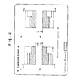
- the display device 106 presents the display shown in Fig. 3, allowing the operator to select the desired coordinate system.
- a design drawing will be expressed in one of four coordinate systems, these pertaining to first, second, third and fourth quadrants.
- the screen of the display device 106 displays each one of these coordinate systems, as well as the numbers 1, 2, 3 and 4 representing the corresponding quadrants. Whichever of the coordinate system numbers 1, 2, 3, 4 has been preset as an initial value will appear after the message reading "PRESENT COORDINATE SYSTEM:".
- the operator responds by using the data input key group 104e (Fig. 2) to enter the numerical value corresponding to the quadrant in which the part on the blueprint is expressed.
- the coordinate system has been selected in this manner, the number of the selected coordinate system appears after the message "PRESENT COORDINATE SYSTEM:".
- the graphic display screen of the display device 106 presents a display of a part contour expressed in terms of shape element symbols that have already been registered in memory. More specifically, as shown in Fig. 4, the display device displays correspondence between a code number and a part contour expressed as a plurality of shape element symbols. The operator views this information to search for the part contour representing the desired graphic.
- the display device displays correspondence between a code number and a part contour expressed as a plurality of shape element symbols.
- the operator views this information to search for the part contour representing the desired graphic.
- the display device 106 displays correspondence between a code number and a part contour expressed as a plurality of shape element symbols.
- the operator views this information to search for the part contour representing the desired graphic.
- the dashed line DL indicates contour of the starting stock.
- the shape element symbol group SEP expresses the contour shown in Fig. 5.
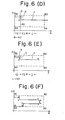
- the next task for the operator is to enter dimensions that specify tool movement.
- the dimensions are entered in order starting from the shape element at the far left of the shape element symbol group SEP.
- these are decoded by the apparatus, which then displays the machining contour on the CRT screen in sequential fashion.
- This serial number is used later for the purpose of indicating a particular point on the machining contour.
- the operator responds by entering the value of the indicated dimension. For example, when "20" is keyed in from the data input key group 104e, the line a is formed into a line segment corresponding to the length 20, with a serial number 2 appearing at the end point of the line. This ends the processing for the entry of the dimension relating to the first shape element symbol ⁇ , causing the symbol ⁇ at the far left of the shape element symbol group to vanish from the screen. Processing for the next shape element symbol ⁇ now takes place.
- the shape to be processed next is given by $, which information causes a straight line b to be drawn on the display screen vertically downwardly from the serial number 2, as shown in Fig. 6(C).
- the foregoing operation ends processing for the entry of the dimension relating to the shape element symbol with said shape element symbol ⁇ vanishing from the display screen.
- a straight line c is drawn to the right from the end point of the line segment b t as illustrated in Fig. 6(D), and operations similar to those described heretofore are performed in such fashion as to set the length of a line sigment c', as shown in Fig. 6(E). These operations are repeated until the entry of part dimensions for describing the contour shown in Fig. 6(F) are completed.
- the input coordinate system, part contour and dimensions are converted into numerical control information, which is then loaded in the RAM 101c to end processing for the creation of the numerical control data.
- the NC mode is established, so that the operator's panel 104 and display device 106 function as a manual data input unit (MDI) having a CRT .
- MDI manual data input unit
- the automatic programming unit 101 When NC machining data have been created by the processing indicated in (A), the automatic programming unit 101 provides the control unit 105 with a signal indicating that the preparations for data transfer are complete. If the operator now presses the transfer key 104b-ll on the operator's panel 104, then the control unit 105 will recognize the abovementioned signal and, in response, will interconnect the automatic programming unit 101 and the NC unit 102 through the second switch 108, and place the NC unit 102 in the reception state, enabling it to receive the NC machining data. When the NC unit 102 has been placed in this state, the control unit 105 instructs the automatic programming unit 101 to start transmitting the NC machining data.
- the automatic programming unit 101 goes to the RAM 101c, which stores the created NC machining data, and transfers the data to the NC unit 102 one block at a time, either serially or in parallel, through the input/output interface 101d, cable CBL1, second switch 108, cable CBL2 and input/output interface 102g.
- the microprocessor 102a in the NC unit 102 reads the NC command data out of a buffer register in the input/output interface 102g, plants the data in the data memory 102c, and determines whether an EOB (end of block) code is present. Thereafter, through the action of the microprocessors lOla, 102a in the automatic programming unit 101 and NC unit 102,.
- the NC machining data are successively transferred from the RAM 101c to the data memory 102c via the route described above, with the transfer processing coming to an end when an EOB code is detected.
- the NC unit 102 when the NC unit 102 is executing NC processing based on the NC machining data planted in the data memory 102c, the NC unit will ignore any operation of the transfer key 104b-11.
- An arrangement is possible, however, wherein an interrupt is applied to the NC unit in such case. In such such an arrangement, the interrupt will place the NC unit 102 in the reception state, with NC processing being resumed after the NC data have been received.
- the NC unit 102 When NC machining data have been stored in the data memory 102c, the NC unit 102 becomes capable of executing numerical control processing (machining control). With the NC unit 102 in this condition, the operator goes to a panel located on the machine tool side (not shown) and, using the panel, places a mode selection switch in a memory run mode position and presses a cycle start button. This causes the microprocessor 102a to read NC machining data out of the data memory 102c in successive fashion, whereby the machine tool is made to perform an NC machining operation under the control of the control program. While the machining control processing is being executed, the operator may press the FAPT key 104a-1 on the operator's panel 104 to establish the FAPT mode, so that automatic programming processing can be carried out at the same time.
- machining control numerical control processing
- the data input/output unit 103 When the operator presses the FAPT key 104d-1 in the I/O selection key group 104d disposed on the operator's panel 104, the data input/output unit 103, under the control of the control unit 105, is connected to the automatic programming unit 101 through the switch 108.
- the NC machining data stored in the RAM 101c is fed into the data input/output unit 103, in accordance with the input/output function possessed by the automatic programming unit 101, through the input/output interface lOld, cable CBL1 and second switch 108.
- the input/output unit 103 such as a floppy disk unit, data reader/puncher or magnetic tape cassette unit, preserves the data on the particular storage medium.
- the data input/output unit 103 When the operator presses the NC key 104d-2 in the I/O selection key group 104d disposed on the operator's panel 104, the data input/output unit 103, under the control of the control unit 105, is connected to the NC unit 102 through the switch 108.
- the NC machining data which are preserved on; say, a floppy disk, paper tape or NC tape in the data input/output unit 103, are planted in the data memory 102c, under the control of the microprocessor 102a, through the second switch 108, cable CBL2 and input/output interface 102g.
- the NC unit 102 can perform machining control independently based on the NC machining data stored in the data memory 102c.
- the automatic programming unit 101 is capable of performing automatic processing in the FAPT mode.
- the FAPT mode is established to enable automatic programming processing, and the display device 106 is devoted to the automatic programming unit 101.
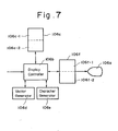
- the latter immediately delivers the first item of picture data to the display device 106, the construction of which is shown in Fig. 7.
- the data is stored in a first storage area 106c-1 of a refresh memory 106c through a display controller 106b.
- the display controller 106b subsequently reads the data out of the first storage area 106c-l and, using a vector generator 106d and character generator 106e, generates a picture in accordance with the data.
- the picture is stored in a first storage area 106f-1 of a picture memory 106f. Thereafter, the picture stored in the first storage area 106f-1 of the picture memory 106f is displayed on a CRT 106a by raster scanning. From this point onward the displayed picture changes based on the progress of the automatic programming operation.
- the NC mode is established to enable N C processing, and the display device 106 is devoted to the NC unit 102.
- pressing the function keys 104c-l through 104c-6 on the operator's panel 104 causes the NC unit 102 to deliver picture data, conforming to the function key pressed, to a second storage area 106c-2 in the refresh memory 106c, where the data are then stored.
- the display controler 106b reads the data out of the second storage area 106c-2, generates a picture and stores the picture in a second storage area 106f-2 of the picture memory 106f. Thereafter, the picture stored in the second storage area 106f-2 is displayed on the CRT 106a by raster scanning.
- picture data are created by the automatic programming unit 101 and NC unit 102 and sent to the display device 106.
- the display device 106 is provided with an editing function, with the picture data being created and displayed by the display device 106 in accordance with the FAPT mode or NC mode, and based on data entered by the operator's panel.
- the picture memory 106f is provided with first and second storage areas for use with unit 101 and unit 102. Accordingly, even if a changeover is made from the FAPT mode, during the course of automatic programming while the display device is displaying the relevant information, to the NC mode so that the operator may perform an operation such as displaying and modifying an offset quantity, followed by restoring the FAPT mode, the previous picture displayed in the FAPT mode prior to the changeover will reappear on the display screen. Likewise, when the FAPT mode is switched to and an operation performed while a picture is being displayed on the display device 106 in the NC mode, the picture will reappear when the NC mode is restored.
- various functions are separated into individual modules, each of which is designed independently, and the modules are combined into a system.
- This appoach facilitates design and maintenance.
- only one operator's panel, display device and data input/output unit need be provided, these being shared by both the automatic programming unit and NC unit. This not only reduces the cost and size of the system but also facilitates operability because the operator can make the necessary inputs at one place.
- the automatic programming unit and NC unit share use of the operator's panel, display device and data input/output unit.
- a modification is possible wherein only the operator's panel is so shared.
Landscapes
- Engineering & Computer Science (AREA)
- Human Computer Interaction (AREA)
- Manufacturing & Machinery (AREA)
- Physics & Mathematics (AREA)
- General Physics & Mathematics (AREA)
- Automation & Control Theory (AREA)
- Numerical Control (AREA)
Applications Claiming Priority (2)
| Application Number | Priority Date | Filing Date | Title |
|---|---|---|---|
| JP57170673A JPS5960506A (ja) | 1982-09-29 | 1982-09-29 | 数値制御システム |
| JP170673/82 | 1982-09-29 |
Publications (2)
| Publication Number | Publication Date |
|---|---|
| EP0109742A2 true EP0109742A2 (de) | 1984-05-30 |
| EP0109742A3 EP0109742A3 (de) | 1986-06-18 |
Family
ID=15909254
Family Applications (1)
| Application Number | Title | Priority Date | Filing Date |
|---|---|---|---|
| EP83305900A Withdrawn EP0109742A3 (de) | 1982-09-29 | 1983-09-29 | Numerisch gesteuerte Anlage |
Country Status (3)
| Country | Link |
|---|---|
| US (1) | US4607327A (de) |
| EP (1) | EP0109742A3 (de) |
| JP (1) | JPS5960506A (de) |
Cited By (9)
| Publication number | Priority date | Publication date | Assignee | Title |
|---|---|---|---|---|
| EP0163737A1 (de) * | 1983-10-26 | 1985-12-11 | Fanuc Ltd. | Vorrichtung zur steuerung eines roboters |
| EP0170704A1 (de) * | 1984-01-10 | 1986-02-12 | Fanuc Ltd. | Numerische steuerungsvorrichtung mit selbsttätiger programmierfunktion |
| GB2163927A (en) * | 1984-08-31 | 1986-03-05 | Gen Electric | Graphic display for a numerical control system |
| FR2569877A1 (fr) * | 1984-08-31 | 1986-03-07 | Gen Electric | Procede de visualisation graphique pour un systeme de commande numerique de machine-outil |
| GB2192471A (en) * | 1986-07-10 | 1988-01-13 | Unilever Plc | Compiling control program |
| FR2617209A1 (fr) * | 1987-06-29 | 1988-12-30 | Tokai Ind Sewing Machine | Machine a broder |
| WO1990002980A1 (de) * | 1988-09-06 | 1990-03-22 | Agie Management Ag | Bearbeitungsstation und verfahren zu ihrem betrieb |
| GB2242543A (en) * | 1990-02-22 | 1991-10-02 | Jobs Spa | Machine tool with integral CAD and NC program generation |
| EP0525531A2 (de) * | 1991-07-30 | 1993-02-03 | Mauser-Werke Oberndorf GmbH | Steuerpult für Bearbeitungs- und Messmaschinen |
Families Citing this family (19)
| Publication number | Priority date | Publication date | Assignee | Title |
|---|---|---|---|---|
| JPS6054012A (ja) * | 1983-09-01 | 1985-03-28 | Mitsubishi Electric Corp | 数値制御装置 |
| JPS61187011A (ja) * | 1985-02-13 | 1986-08-20 | Yaskawa Electric Mfg Co Ltd | 数値制御装置のグラフィック表示装置 |
| JPS6239157A (ja) * | 1985-08-13 | 1987-02-20 | Kitamura Kikai Kk | Nc工作機械 |
| JPS62119608A (ja) * | 1985-11-20 | 1987-05-30 | Fanuc Ltd | 対話形プログラミング装置 |
| JPS62232004A (ja) * | 1986-04-01 | 1987-10-12 | Fanuc Ltd | Ncシステム |
| US4918602A (en) * | 1987-07-15 | 1990-04-17 | Computer Associates International, Inc. | Data processing system and method |
| US5099413A (en) * | 1987-12-12 | 1992-03-24 | Sadashiro Sakai | System which reads type and position of task element marks on a matrix of program tasks for automatically generating programs |
| JPH01217605A (ja) * | 1988-02-26 | 1989-08-31 | Fanuc Ltd | 多軸多系統工作機械用数値制御装置 |
| JP2534305B2 (ja) * | 1988-03-09 | 1996-09-11 | ファナック株式会社 | 数値制御装置 |
| US5084813A (en) * | 1988-04-20 | 1992-01-28 | Kabushiki Kaisha Toshiba | Rule based system for synthesizing a program suited for a target system in response to an input target system specification |
| US5293106A (en) * | 1989-12-11 | 1994-03-08 | Murata Kikai Kabushiki Kaisha | Program reviewing device in numerical control processing apparatus |
| BR9004680A (pt) * | 1990-09-19 | 1991-09-10 | Ibm Brasil Ltda | Aparelho para sensoramento,controle e monitoramento,em tempo real para reduzir qualquer tempo de detecao de erro de processo e consequente correcao,sem disconectar totalmente o sistema ao qual esta conectado,independentemente de protocolos de comunicacao,metodos para implementa-lo e utiliza-lo e sistema que inclui tal aparelho |
| JPH06202724A (ja) * | 1992-12-28 | 1994-07-22 | Fanuc Ltd | 数値制御装置 |
| US5465215A (en) * | 1994-07-07 | 1995-11-07 | Cincinnati Milacron Inc. | Numerical control method and apparatus |
| JP3352562B2 (ja) * | 1995-03-31 | 2002-12-03 | 東芝機械株式会社 | プロセスコントローラのマンマシンインタフェース装置 |
| KR100421788B1 (ko) * | 1996-11-07 | 2004-07-16 | 가부시키가이샤 미츠토요 | 엔시가공에있어서의엔시프로그램해석장치및가공방법 |
| JPH11345009A (ja) * | 1998-06-02 | 1999-12-14 | Fanuc Ltd | 数値制御装置 |
| DE10157577A1 (de) * | 2001-11-23 | 2003-12-24 | Heidenhain Gmbh Dr Johannes | Vorrichtung und Verfahren zur Erstellung und/oder Änderung von NC-Programmen oder NC-Tabellen |
| JP3893334B2 (ja) * | 2002-08-23 | 2007-03-14 | ファナック株式会社 | 多系統数値制御装置 |
Citations (3)
| Publication number | Priority date | Publication date | Assignee | Title |
|---|---|---|---|---|
| GB2054909A (en) * | 1979-07-20 | 1981-02-18 | Heidenhain Gmbh Dr Johannes | Process and Circuit Arrangement for Programming and/or Amending Programs in Numerically Controlled Machines |
| US4281379A (en) * | 1978-12-18 | 1981-07-28 | Mcdonnell Douglas Corporation | Computer driven control system for a numerically controlled machine tool |
| EP0034017A2 (de) * | 1980-02-01 | 1981-08-19 | Fanuc Ltd. | Programmierbare Folgesteuervorrichtung |
Family Cites Families (8)
| Publication number | Priority date | Publication date | Assignee | Title |
|---|---|---|---|---|
| BE757805A (fr) * | 1969-10-21 | 1971-04-21 | Motorola Inc | Appareil intermediaire de commande pour une calculatrice |
| US3878983A (en) * | 1973-10-29 | 1975-04-22 | Iii Samuel M Hamill | System for numerical control of a machine tool |
| US4314330A (en) * | 1973-12-03 | 1982-02-02 | Houdaille Industries, Inc. | Machine tool data system |
| US3970830A (en) * | 1974-06-24 | 1976-07-20 | Cone-Blanchard Machine Company | Computer controlled machine tool contouring system |
| US4140953A (en) * | 1976-03-03 | 1979-02-20 | Unimation, Inc. | Real time program modification apparatus |
| US4059745A (en) * | 1976-09-29 | 1977-11-22 | Fischer & Porter Co. | Override process control system |
| JPS56140411A (en) * | 1980-04-04 | 1981-11-02 | Fanuc Ltd | Numerical control system of machine tool |
| DE3028708A1 (de) * | 1980-07-29 | 1982-02-11 | Dr. Johannes Heidenhain Gmbh, 8225 Traunreut | Verfahren zur programmierung bahngesteuerter maschinen |
-
1982
- 1982-09-29 JP JP57170673A patent/JPS5960506A/ja active Pending
-
1983
- 1983-09-29 EP EP83305900A patent/EP0109742A3/de not_active Withdrawn
- 1983-09-29 US US06/536,879 patent/US4607327A/en not_active Expired - Fee Related
Patent Citations (3)
| Publication number | Priority date | Publication date | Assignee | Title |
|---|---|---|---|---|
| US4281379A (en) * | 1978-12-18 | 1981-07-28 | Mcdonnell Douglas Corporation | Computer driven control system for a numerically controlled machine tool |
| GB2054909A (en) * | 1979-07-20 | 1981-02-18 | Heidenhain Gmbh Dr Johannes | Process and Circuit Arrangement for Programming and/or Amending Programs in Numerically Controlled Machines |
| EP0034017A2 (de) * | 1980-02-01 | 1981-08-19 | Fanuc Ltd. | Programmierbare Folgesteuervorrichtung |
Cited By (14)
| Publication number | Priority date | Publication date | Assignee | Title |
|---|---|---|---|---|
| EP0163737A4 (de) * | 1983-10-26 | 1987-11-02 | Fanuc Ltd | Vorrichtung zur steuerung eines roboters. |
| EP0163737A1 (de) * | 1983-10-26 | 1985-12-11 | Fanuc Ltd. | Vorrichtung zur steuerung eines roboters |
| EP0170704A4 (de) * | 1984-01-10 | 1988-04-06 | Fanuc Ltd | Numerische steuerungsvorrichtung mit selbsttätiger programmierfunktion. |
| EP0170704A1 (de) * | 1984-01-10 | 1986-02-12 | Fanuc Ltd. | Numerische steuerungsvorrichtung mit selbsttätiger programmierfunktion |
| GB2163927A (en) * | 1984-08-31 | 1986-03-05 | Gen Electric | Graphic display for a numerical control system |
| FR2569877A1 (fr) * | 1984-08-31 | 1986-03-07 | Gen Electric | Procede de visualisation graphique pour un systeme de commande numerique de machine-outil |
| FR2569876A1 (fr) * | 1984-08-31 | 1986-03-07 | Gen Electric | Procede et dispositif de visualisation graphique pour un systeme de commande numerique de machine-outil |
| GB2192471A (en) * | 1986-07-10 | 1988-01-13 | Unilever Plc | Compiling control program |
| FR2617209A1 (fr) * | 1987-06-29 | 1988-12-30 | Tokai Ind Sewing Machine | Machine a broder |
| WO1990002980A1 (de) * | 1988-09-06 | 1990-03-22 | Agie Management Ag | Bearbeitungsstation und verfahren zu ihrem betrieb |
| GB2242543A (en) * | 1990-02-22 | 1991-10-02 | Jobs Spa | Machine tool with integral CAD and NC program generation |
| GB2242543B (en) * | 1990-02-22 | 1994-02-02 | Jobs Spa | Tridimensional multifunction machine tool |
| EP0525531A2 (de) * | 1991-07-30 | 1993-02-03 | Mauser-Werke Oberndorf GmbH | Steuerpult für Bearbeitungs- und Messmaschinen |
| EP0525531A3 (en) * | 1991-07-30 | 1993-06-09 | Mauser-Werke Oberndorf Gmbh | Control panel for processing and measuring machines |
Also Published As
| Publication number | Publication date |
|---|---|
| EP0109742A3 (de) | 1986-06-18 |
| JPS5960506A (ja) | 1984-04-06 |
| US4607327A (en) | 1986-08-19 |
Similar Documents
| Publication | Publication Date | Title |
|---|---|---|
| US4607327A (en) | Modular numerical control system with automatic programming function | |
| US4723207A (en) | Machine operator's panel for numerical control | |
| US5406473A (en) | Programmable controller | |
| US4797811A (en) | Dual language numerical controller | |
| US4660148A (en) | Part program creation method | |
| JPS6243703A (ja) | 数値制御システム | |
| EP0144446B1 (de) | Farbanzeigeverfahren für numerische steuervorrichtung mit automatischer programmierung | |
| US4697249A (en) | Method and apparatus for creating part program data using a tablet | |
| US4627003A (en) | Method and apparatus for creating numerical control data | |
| EP0079388B1 (de) | Numerisches steuerverfahren | |
| US4555590A (en) | Method and apparatus for entering graphics | |
| EP0144428B1 (de) | Verfahren zur unterschiedlichen behandlung von winkeldaten | |
| JP2735209B2 (ja) | 数値制御装置 | |
| US4396973A (en) | Programmable sequence controller | |
| EP0377939A1 (de) | Robotersteuerungssystem zur Steuerung einer Mehrzahl von industriellen Robotern | |
| EP0088565A1 (de) | Verfahren und Vorrichtung zum Steuern des Informationseingangs bei einem Koordinateneingabegerät | |
| EP0092312B1 (de) | Verfahren und Gerät zum Anzeigen von Leiterdiagrammen | |
| US4616309A (en) | Numerical control system | |
| JPS6232805B2 (de) | ||
| EP0087949B1 (de) | Verfahren und Vorrichtung zum Erzeugen von numerischen Kontrolldaten | |
| EP0170704A1 (de) | Numerische steuerungsvorrichtung mit selbsttätiger programmierfunktion | |
| EP0160704B1 (de) | Datenein-/ausgabeverfahren für ein anwendungssystem in einer numerischen steuervorrichtung | |
| EP0332703A1 (de) | Dateneingabesystem | |
| JPS603926B2 (ja) | 放電加工制御方法 | |
| EP0089194B1 (de) | Verfahren und Gerät zum Anzeigen von Leiterdiagrammen |
Legal Events
| Date | Code | Title | Description |
|---|---|---|---|
| PUAI | Public reference made under article 153(3) epc to a published international application that has entered the european phase |
Free format text: ORIGINAL CODE: 0009012 |
|
| AK | Designated contracting states |
Designated state(s): DE FR GB |
|
| PUAL | Search report despatched |
Free format text: ORIGINAL CODE: 0009013 |
|
| AK | Designated contracting states |
Kind code of ref document: A3 Designated state(s): DE FR GB |
|
| 17P | Request for examination filed |
Effective date: 19861029 |
|
| 17Q | First examination report despatched |
Effective date: 19880229 |
|
| STAA | Information on the status of an ep patent application or granted ep patent |
Free format text: STATUS: THE APPLICATION IS DEEMED TO BE WITHDRAWN |
|
| 18D | Application deemed to be withdrawn |
Effective date: 19900721 |
|
| RIN1 | Information on inventor provided before grant (corrected) |
Inventor name: MATSUMURA, TERUYUKI Inventor name: SEKI, MASAKI Inventor name: KURAKAKE, MITSUO Inventor name: TANAKA, KUNIO Inventor name: KISHI, HAJIMU |