EP0109475B1 - Dispositif pour corriger la longueur de bandes élastomères dans la fabrication des pneus - Google Patents
Dispositif pour corriger la longueur de bandes élastomères dans la fabrication des pneus Download PDFInfo
- Publication number
- EP0109475B1 EP0109475B1 EP83101394A EP83101394A EP0109475B1 EP 0109475 B1 EP0109475 B1 EP 0109475B1 EP 83101394 A EP83101394 A EP 83101394A EP 83101394 A EP83101394 A EP 83101394A EP 0109475 B1 EP0109475 B1 EP 0109475B1
- Authority
- EP
- European Patent Office
- Prior art keywords
- drum
- elastomeric material
- length
- tire building
- building drum
- Prior art date
- Legal status (The legal status is an assumption and is not a legal conclusion. Google has not performed a legal analysis and makes no representation as to the accuracy of the status listed.)
- Expired
Links
Images


Classifications
-
- B—PERFORMING OPERATIONS; TRANSPORTING
- B29—WORKING OF PLASTICS; WORKING OF SUBSTANCES IN A PLASTIC STATE IN GENERAL
- B29D—PRODUCING PARTICULAR ARTICLES FROM PLASTICS OR FROM SUBSTANCES IN A PLASTIC STATE
- B29D30/00—Producing pneumatic or solid tyres or parts thereof
- B29D30/06—Pneumatic tyres or parts thereof (e.g. produced by casting, moulding, compression moulding, injection moulding, centrifugal casting)
- B29D30/08—Building tyres
- B29D30/20—Building tyres by the flat-tyre method, i.e. building on cylindrical drums
- B29D30/30—Applying the layers; Guiding or stretching the layers during application
- B29D30/3007—Applying the layers; Guiding or stretching the layers during application by feeding a sheet perpendicular to the drum axis and joining the ends to form an annular element
-
- B—PERFORMING OPERATIONS; TRANSPORTING
- B29—WORKING OF PLASTICS; WORKING OF SUBSTANCES IN A PLASTIC STATE IN GENERAL
- B29D—PRODUCING PARTICULAR ARTICLES FROM PLASTICS OR FROM SUBSTANCES IN A PLASTIC STATE
- B29D30/00—Producing pneumatic or solid tyres or parts thereof
- B29D30/06—Pneumatic tyres or parts thereof (e.g. produced by casting, moulding, compression moulding, injection moulding, centrifugal casting)
- B29D30/0681—Parts of pneumatic tyres; accessories, auxiliary operations
- B29D2030/0682—Inner liners
-
- B—PERFORMING OPERATIONS; TRANSPORTING
- B29—WORKING OF PLASTICS; WORKING OF SUBSTANCES IN A PLASTIC STATE IN GENERAL
- B29D—PRODUCING PARTICULAR ARTICLES FROM PLASTICS OR FROM SUBSTANCES IN A PLASTIC STATE
- B29D30/00—Producing pneumatic or solid tyres or parts thereof
- B29D30/06—Pneumatic tyres or parts thereof (e.g. produced by casting, moulding, compression moulding, injection moulding, centrifugal casting)
- B29D30/38—Textile inserts, e.g. cord or canvas layers, for tyres; Treatment of inserts prior to building the tyre
- B29D30/44—Stretching or treating the layers before application on the drum
- B29D2030/4406—Adjusting the positions of the layers
- B29D2030/4418—Adjusting the positions of the layers laterally, e.g. sideways
-
- B—PERFORMING OPERATIONS; TRANSPORTING
- B29—WORKING OF PLASTICS; WORKING OF SUBSTANCES IN A PLASTIC STATE IN GENERAL
- B29D—PRODUCING PARTICULAR ARTICLES FROM PLASTICS OR FROM SUBSTANCES IN A PLASTIC STATE
- B29D30/00—Producing pneumatic or solid tyres or parts thereof
- B29D30/06—Pneumatic tyres or parts thereof (e.g. produced by casting, moulding, compression moulding, injection moulding, centrifugal casting)
- B29D30/38—Textile inserts, e.g. cord or canvas layers, for tyres; Treatment of inserts prior to building the tyre
- B29D30/44—Stretching or treating the layers before application on the drum
- B29D2030/4437—Adjusting the dimensions of the layers
- B29D2030/4462—Adjusting the dimensions of the layers by using grasping means
-
- B—PERFORMING OPERATIONS; TRANSPORTING
- B29—WORKING OF PLASTICS; WORKING OF SUBSTANCES IN A PLASTIC STATE IN GENERAL
- B29D—PRODUCING PARTICULAR ARTICLES FROM PLASTICS OR FROM SUBSTANCES IN A PLASTIC STATE
- B29D30/00—Producing pneumatic or solid tyres or parts thereof
- B29D30/06—Pneumatic tyres or parts thereof (e.g. produced by casting, moulding, compression moulding, injection moulding, centrifugal casting)
- B29D30/38—Textile inserts, e.g. cord or canvas layers, for tyres; Treatment of inserts prior to building the tyre
- B29D30/44—Stretching or treating the layers before application on the drum
- B29D2030/4468—Holding the layers
- B29D2030/4493—Holding the layers by using suction means, e.g. vacuum
Definitions
- This invention relates to a method for applying a length of elastomeric material having a first and second end to a drum according to the preamble of claim 1 and an apparatus for correcting the length of a piece of elastomeric material according to the preamble of claim 3.
- the known apparatus is directed to a method and apparatus wherein the outer ply intended to be applied to the tire building drum is accurately measured using a combination of a photocell array and a light curtain in order to measure the actual length of the outer ply to be applied to the tire building drum.
- the measured value is then compared with the theoretical length required to wrap the tread ply about the tire building drum and a value related to the difference between the actual measured length of the tread ply and the theoretical length of the tread ply required to wrap about the tire building drum is provided to a mechanical device which is adapted to adjust the gap between application rollers and the tire building drum in order to effect a stretching of the ply as it is being applied to the tire building drum in order to change the length of the ply from the actual measured length to the theoretical length.
- this prior art teaching employs a method whereby the actual length of the tread ply that is to be applied to the tire building drum is measured and is subsequently stretched to the theoretically desired length as it is being applied to the tire building drum.
- the accuracy of the application of the tread ply member to the tire building drum is dependent upon the lack of variance between the theoretical length required for the tread ply to wrap about the tire building drum and the actual length required to wrap about the tire building drum which may be significantly different from the theoretical length due to variances in the diameter of the tire building drum.
- Variance in the diameter of the tire building drum will cause a corresponding difference in the length of ply material required to wrap around the tire building drum. This is especially critical in cases where it is desired to butt splice the ends of the material being applied to the tire building drum such as in the application of outer tread plies and thus requires an accurate application to the tire building drum in order to avoid either overlap of the ends of the material or gaps therein due to the improper length of material being applied thereto.
- the present invention thus specifically provides method and apparatus which allow for stock width measurement and precise centering without the possible edge distortion of known guiding systems.
- the instant invention comprising an applicator 11, a splice conveyor 12, a feed mechanism 13 and a holding roll 14.
- the applicator 11 is adapted to apply innerliner material 16 to the tire building drum 15.
- a large roll of a continuous length of innerliner material 16 is fed from the feed mechanism 13 to the splice conveyor 12.
- the splice conveyor 12 is adapted to allow lengths of innerliner material from different rolls to be joined in order to form a continuous length thereof. From the splice conveyor 12, the innerliner material travels to the applicator 11.
- the applicator 11 grasps the end of the innerliner material 16 and moves the end to the bottom of the tire building drum 15 and presses the innerliner material 16 to the bottom of the drum 15 causing the innerliner material 16 to adhere to the bottom of the tire building drum 15 due to the tackiness of the innerliner material 16.
- the tire building drum 15 is then rotated in order to cause the innerliner material 16 to partially wrap around the tire building drum 15. After a sufficient portion of innerliner material 16 has been wrapped on the tire building drum 15, the innerliner material 16 is severed by a cutting mechanism contained within the applicator 11.
- the applicator 11, in conjunction with rotation of the tire building drum 15, then causes the remainder of the cut piece of innerliner material 16 to be applied to the tire building drum 15.
- the holding roll 14 is utilized to assist in holding the innerliner material 16 on the tire building drum 15 for reasons which will be discussed more fully below.
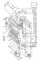
- FIG. 2 of the drawings there is shown a simplified schematic diagram showing the major operative elements of the applicator 11.
- the applicator 11 rests on base 20.
- Sub-frame 21 is supported upon the base 20 by means of pivot connections 22 and air spring 23.
- the sub-frame 21 may be pivoted about the pivot connections 22 relative to the fixed base 20 by causing the air spring 23 to either inflate or deflate by means of pneumatic circuitry well known to one skilled in the art.
- Air table 25 is comprised of a flattened rectangular box-like structure having a perforated upper surface 26 and a plurality of fans 27 mounted on the bottom of the air table 25 in order to introduce air into the generally rectangular box-like structure.
- the air introduced into the generally box-like structure by the fans 27 is exhausted through the top of the box-like structure through the perforated upper surface 26 thus providing an air-bearing type surface over which innerliner material 16 may be transported.
- the air-bearing provided by the air table 25 facilitates both longitudinal and latitudinal movement of the innerliner material upon the air table 25 to allow positioning thereof.
- baffle 28 Located on the side of the air table 25 is baffle 28 which may be adjusted to either increase or decrease the opening of the baffle 28 in order to adjust the amount of air exhausted through the perforated upper surface 26.
- fiber optic guidance unit 30 Disposed proximate to the air table 25 is fiber optic guidance unit 30 which is comprised of two linear arrays of fiber optic cables in optic communication with a series of photo electric source/ detectors which are utilized to determine the position of the innerliner material 16 with respect to the fiber optic guidance unit 30 in order to facilitate positioning of the innerliner material as more fully described below.
- Lateral adjustment unit 40 is comprised of a manifold 41 having a series of orifices in the upper surface thereof to which a vacuum may be selectively applied.
- the manifold 41 may be laterally displaced by means of drive motor 42, rotating lead screw 43, acting in conjunction with an engagement nut on manifold 41 in order to allow the manifold 41 to be laterally displaced.
- the position of the lateral adjustment unit 40 can be determined with rotary encoder 45.
- gripper unit 50 Disposed above the lateral adjustment unit 40 is gripper unit 50 which is adapted to grasp the innerliner material upon actuation of a cylinder (not shown) by means of a pair of interlocking fingers which may be moved relative to one another by means of the cylinder.
- crush cutter 56 which is comprised of two eccentrically mounted cutting elements 57 adapted to be rotated into an engaging position by a cylinder (not shown) in order to sever the innerliner material 16 disposed between the cutting elements 57.
- the details of construction of the crush cutter are more fully illustrated in U.S. Patent Application Serial No. 321,983 filed in the name of James E. Hogan et al, which patent application is hereby incorporated by reference.
- the upper guide member 60 Disposed forward and above the crush cutter 56 is upper guide member 60.
- the upper guide member 60 is comprised of a manifold 61 having on the bottom thereof a plurality of cups 62 to which either a vacuum or air pressure may be applied.
- the manifold is mounted via cylinder 63 to slide member 64 which is adapted to slide along the track 65 by means of actuation of cylinder 66.
- the upper guide member 60 is utilized to transport the end of the innerliner material 16. It should be appreciated that the manifold 61 may be moved up and down by means of cylinder 63 and longitudinally by means of cylinder 66.
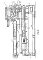
- the transfer unit 70 is comprised of a front manifold 71 which is fixedly attached to transfer frame 72 and rear manifold 73 which is linked to transfer frame 72 by links 74. Pivotly attached to the links 74 is cylinder 75 having its barrel end pivotly attached to the transfer frame 72. The actuation of the cylinder 75 causes the links 74 to be pivoted about their common connection thereby causing the rear manifold 73 to be raised or lowered.
- the transfer frame 72 is longitudinally movable by means of drive motor 76 driving lead screw 77 which is engaged with lead screw nut 78 which is fixedly attached to the transfer frame 72. There is thus provided a means for longitudinally moving the transfer unit 70 from a position proximate to the manifold 61 to a position proximate to the bottom of tire building drum 15.
- the position of the transfer unit 70 can be determined from the outputs provided by encoder 79.
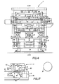
- FIG. 5 of the drawings there is shown a simplified schematic drawing of the main operative elements of the applicator 11. Specifically, there is shown the innerliner material 16 disposed on the lateral adjustment unit 40 and the transfer unit 70.. The gripper unit 50 is open and the crush cutter 56 is also open while the upper guide member 60 is in its raised rearward position. The transfer frame 72 is also in its most rearward position. The leading edge of the innerlinner material 16 is held to the rear manifold 73 by a vacuum applied thereto. This configuration represents the starting position of the sequence of operation of the applicator 11.
- the transfer unit 70 is moved forward toward the tire building drum 15. Simultaneously the drum 15 is rotated to position a tack strip on the drum 15 at its dead center bottom and the air spring 23 is inflated in order to cause the sub-frame 21 to pivot about pivot connections 22 to thereby cause transfer frame 72 and thus transfer unit 70 to move upwardly toward the tire building drum 15.
- the transfer unit 70 has been positioned such that the leading edge of the innerliner material 16 has been placed in contact with the tack strip of the tire building drum 15 in order to cause the innerliner material 16 to adhere to the tack strip of the tire building drum 15.
- the transfer unit 70 is moved downwardly and retracted toward the applicator 11.
- the drum 15 is rotated and the transfer unit 70 is moved forward synchronously.
- air pressure is provided to the rear manifold 73 and the sub-frame 21 is simultaneously lowered by air spring 23 in order to effect the transfer of the innerliner material 16 to the tire building drum 15.
- the fiber optic guidance unit 30 as shown in Figure 18 of the drawings is comprised of a mounting plate 81 having an opening therein 82 through which the innerliner material 16 may pass. Disposed towards the ends of the opening 82 are a series of paired receptacles for receiving the ends of fiber optic cables. At each end of the mounting plate 81 are located eight pairs of fiber optic cable receptacles located approximately one-half inch apart in which fiber optic cables may be mounted.
- the fiber optic cables 83 mounted within the mounting plate 81 are in communication with a plurality of conventional photoelectric source/detectors 84 such that oppositely disposed pairs of fiber optic cables are in optical communication with a given photoelectric source/detector such that any interruption of the light passing between the oppositely disposed pairs of fiber optic cables mounted in the mounting plate 81 will thus produce an output signal from the corresponding photoelectric source/detector 84.
- the output signal is provided to control 91 which utilizes the output signals to control drive motor 42 and, hence, the latitudinal position of lateral adjustment unit 40.
- the control 91 is Struthers-Dunn Director 4001 programable controller manufactured by Struthers-Dunn, Inc. of Bettendorf, Iowa.
- the innerliner material 16 will cause the light path between various ones of the ends of fiber optic cables to be interrupted thus providing an indication of the position of the innerliner material within the opening 82 of the mounting plate 81.
- the lateral adjustment unit 40 is caused to transport the innerliner material to one side of the mounting plate 81 in order to cause an equal or symetri- cal number of fiber optic pairs to have their light paths interrupted.
- the innerliner material 16 is then moved by the lateral adjustment unit 40 to the opposite side of the mounting plate 81 until an unequal or nonsymetrical number of photo detectors have their light paths interrupted.
- the encoder associated with the lateral adjustment unit measures the position of the lateral adjustment unit.
- the lateral adjustment unit then causes the innerliner material 16 to be moved in the opposite direction until another point of non- symetry is obtained. At this point the pulse count is then measured and divided in order to obtain the excess width of the innerliner material 16.
- the innerliner material is then moved back half the distance of the excess width to center it within the mounting plate 81.
- the above described method of centering the innerliner material within the applicator 11 allows for the accurate centering of innerliner material wherein the width of the innerliner material may vary substantially.
- the method described above thus essentially determines where the center of the innerliner material is located and then positions the center of the innerliner material coincident with the centerline of the applicator 11. This centering is accomplished without physically touching the edges of the innnerliner material 16.
- the transfer unit 70 is being retracted towards the crush cutter 56.
- Figure 9 discloses step 5 of the operating sequence wherein cutting elements 57 of the crush cutter 56 are rotated in order to cut the innerliner material 16.
- Step 6 shown in Figure 10 discloses the next step of the operating sequence wherein the gripper unit 50 is caused to grab the innerliner material 16.
- the manifold 61 with its suction cups 62 is lowered to contact the innerliner material and grip the innerliner material by means of a vacuum applied to the manifold 61.
- the manifold 61 is then raised slightly.
- the next step in the operating sequence as shown in Figure 11 discloses the rotating of the cutting elements 57 in order to allow the opening of the crush cutter 56 thereby allowing the gripper unit 50 and the manifold 61 to simultaneously move forward.
- the gripper unit 50 and manifold 61 are moved forward the tire building drum is simultaneously rotated to take up the slack in the innerliner material 16.
- the manifold 61 After the manifold 61 is moved over the front manifold 71, the manifold 61 is lowered and a vacuum is applied to the front manifold 71 while removing the vacuum from the manifold 61 and causing air pressure to be applied to the manifold 61, thus causing a transfer of the innerliner material 16 from the suction cups 62 of manifold 61 to the front manifold 71 of transfer unit 70. The manifold 61 is then raised clear of the innnerliner material 16.
- the upper guide member 60 and the gripper unit 50 are retracted back towards the air table 25 causing the innerliner material 16 to separate from where the innerliner material had been crushed by the crush cutter 56.
- the transfer frame 72 is moved back in order to correct for the length of innerliner material cut.
- the length of the innerliner material 16 cut is slightly shorter than the circumference of the tire building drum 15.
- the cut portion of the innerliner material 16 is stretched by the retraction of the transfer frame 72 as disclosed in Figure 12 in order to cause the cut length of innerliner material to assume the correct length in order that it may be properly spliced at its ends.
- the innerliner 16 may be accurately applied to the tire building drum 15, it is necessary that the tire building drum be controlled with extreme accuracy. Due to the size and moment of inertia of the tire building drum, it is extremely difficult to accurately stop the drum precisely at a specified position. However, it is relatively easy to measure the angular position of the tire building drum by means of a rotary encoder 17 as shown in Figure 2 of the drawings. As shown in Figure 2, the rotary encoder 17 is driven via an intermediate jack shaft from the shaft of the tire building drum 15. Since the rotary encoder 17 is driven from the shaft as opposed to the surface of the tire building drum 15, the rotary encoder 17 measures angular displacement and not circumferential displacement of the tire building drum 15.
- the rotary encoder 17 thus accurately measures the angular position at which the first end of the innerliner material 16 is applied to the tire building drum as shown in Figure 7 of the drawings.
- the angular position is in the form of a count corresponding to the output of the rotary encoder 17.
- the tire building drum is then rotated for a predetermined fixed period of time and the angular displacement represented by the count output of the rotary encoder 17 is measured.
- the first count output representing the angular position of the tire building drum at which the first end of the innerliner material 16 was applied to the tire building drum is subtracted from the count obtained as a result of rotating the building drum for the predetermined fixed period of time.
- the resulting difference is an accurate value corresponding to the length of innerliner material that has already been applied to the tire building drum. Therefore. it can be readily determined the length of innerliner material needed to apply to the remainder of the tire building drum 15.
- the innerliner material 16 is then cut to thereby produce a length of innerliner material 16 having a length shorter than the nominal circumference of the tire building drum 15. It should be appreciated that since the instant invention is intended to be used in conjunction with a system employing a plurality of tire building drums 15, the length of innerliner material 16 must be shorter than the circumference of the smallest tire building drum.
- the tire building drum 15 is then rotated simultaneously while the transfer unit 70 is moved toward the tire building drum 15 to cause the cut piece of innerliner material 16 to wrap around the tire building drum 15.
- the coordination of the rotation of the tire building drum 15 and the transfer unit 70 is such that the end of the innerliner material 16 will precisely overlap the previously applied end of the innerliner material. It should be noted that by measuring the angular displacement of the tire building drum instead of its circumferential distance, variations in the diameter of the tire building drum may be compensated for by the stretching of the innerliner material 16 during its application to the tire building drum 15. During the stretching of the innerliner material 16, the holding roll 14 is biased against the tire building drum 15 in order to cause the innerliner material 16 to be wrapped about the tire building drum 15.
- step number 10 as disclosed by Figure 14 the transfer unit 70 passes under the tire. building drum 15 and the two ends of the innerliner material are spliced together. The transfer unit 70 is then lowered and retracted back to the applicator 11.
- step 12 is disclosed wherein gripper unit 50 releases the inherliner material 16 and a vacuum is caused to be placed on rear manifold 73 of transfer unit 70 in order to transfer the innerliner material from gripper unit 50 to transfer unit 70.
Landscapes
- Engineering & Computer Science (AREA)
- Mechanical Engineering (AREA)
- Tyre Moulding (AREA)
Claims (6)
Applications Claiming Priority (2)
| Application Number | Priority Date | Filing Date | Title |
|---|---|---|---|
| US42473682A | 1982-09-27 | 1982-09-27 | |
| US424736 | 1982-09-27 |
Publications (3)
| Publication Number | Publication Date |
|---|---|
| EP0109475A2 EP0109475A2 (fr) | 1984-05-30 |
| EP0109475A3 EP0109475A3 (en) | 1985-08-28 |
| EP0109475B1 true EP0109475B1 (fr) | 1988-06-01 |
Family
ID=23683677
Family Applications (1)
| Application Number | Title | Priority Date | Filing Date |
|---|---|---|---|
| EP83101394A Expired EP0109475B1 (fr) | 1982-09-27 | 1983-02-14 | Dispositif pour corriger la longueur de bandes élastomères dans la fabrication des pneus |
Country Status (9)
| Country | Link |
|---|---|
| EP (1) | EP0109475B1 (fr) |
| JP (1) | JPS5955733A (fr) |
| BR (1) | BR8302629A (fr) |
| CA (1) | CA1211354A (fr) |
| DE (1) | DE3376815D1 (fr) |
| ES (1) | ES8403376A1 (fr) |
| MX (1) | MX154311A (fr) |
| NZ (1) | NZ203260A (fr) |
| ZA (1) | ZA831358B (fr) |
Families Citing this family (8)
| Publication number | Priority date | Publication date | Assignee | Title |
|---|---|---|---|---|
| DE3421831A1 (de) * | 1984-06-13 | 1985-12-19 | Fried. Krupp Gmbh, 4300 Essen | Verfahren zum aufbau von luftreifen-rohlingen |
| JPH0813515B2 (ja) * | 1987-07-09 | 1996-02-14 | 株式会社ブリヂストン | 帯状部材の端部挟持装置 |
| JP3190051B2 (ja) * | 1990-12-07 | 2001-07-16 | 株式会社ブリヂストン | 帯状部材の貼付け方法および装置 |
| JP3179131B2 (ja) * | 1991-05-24 | 2001-06-25 | 株式会社ブリヂストン | 帯状部材の貼付け方法および装置 |
| EP0518691A3 (en) * | 1991-06-12 | 1993-07-21 | Bridgestone Corporation | Method and apparatus for attaching belt-shaped member to forming drum |
| DE4407964A1 (de) * | 1994-03-10 | 1995-09-14 | Continental Ag | Verfahren und Vorrichtung zum automatischen Auflegen und Spleißen von Materialbahnen auf eine Reifenaufbautrommel |
| CN104159951B (zh) * | 2012-03-08 | 2017-06-13 | 可隆工业株式会社 | 用于轮胎内衬的膜、制造用于轮胎内衬的膜的方法、充气轮胎和制造充气轮胎的方法 |
| NL2013038B1 (en) * | 2014-06-19 | 2016-07-06 | Vmi Holland Bv | Tire building machine for centering a tire component. |
Family Cites Families (3)
| Publication number | Priority date | Publication date | Assignee | Title |
|---|---|---|---|---|
| US3728181A (en) * | 1970-09-28 | 1973-04-17 | Bandag Inc | Application of tread strip to tire casing |
| US4096008A (en) * | 1974-07-05 | 1978-06-20 | Victor E. Buehrle | Method of manufacture and retreading of tires |
| DE2819410A1 (de) * | 1978-05-03 | 1979-11-08 | Metzeler Kautschuk | Verfahren zur aufbringung eines laufstreifens auf eine reifenaufbautrommel sowie vorrichtung zur durchfuehrung des verfahrens |
-
1983
- 1983-02-11 NZ NZ203260A patent/NZ203260A/en unknown
- 1983-02-14 EP EP83101394A patent/EP0109475B1/fr not_active Expired
- 1983-02-14 DE DE8383101394T patent/DE3376815D1/de not_active Expired
- 1983-02-17 CA CA000421807A patent/CA1211354A/fr not_active Expired
- 1983-02-28 ZA ZA831358A patent/ZA831358B/xx unknown
- 1983-03-18 MX MX196627A patent/MX154311A/es unknown
- 1983-04-27 JP JP58073110A patent/JPS5955733A/ja active Granted
- 1983-05-04 ES ES522092A patent/ES8403376A1/es not_active Expired
- 1983-05-19 BR BR8302629A patent/BR8302629A/pt not_active IP Right Cessation
Also Published As
| Publication number | Publication date |
|---|---|
| JPS5955733A (ja) | 1984-03-30 |
| NZ203260A (en) | 1986-04-11 |
| ES522092A0 (es) | 1984-04-01 |
| ES8403376A1 (es) | 1984-04-01 |
| DE3376815D1 (en) | 1988-07-07 |
| EP0109475A3 (en) | 1985-08-28 |
| EP0109475A2 (fr) | 1984-05-30 |
| BR8302629A (pt) | 1984-05-15 |
| MX154311A (es) | 1987-06-30 |
| CA1211354A (fr) | 1986-09-16 |
| JPS615899B2 (fr) | 1986-02-21 |
| ZA831358B (en) | 1983-11-30 |
Similar Documents
| Publication | Publication Date | Title |
|---|---|---|
| US4824001A (en) | Method for centering materials | |
| US4874443A (en) | Method for applying elastomeric material onto a drum | |
| EP0776757B1 (fr) | Dispositif et procédé pour l'application d'une bande de roulement de pneumatique | |
| KR850001544B1 (ko) | 고무시이트 재료의 반송 성형 장치(搬送成形裝置) | |
| US4608890A (en) | Method of cutting elastomeric material | |
| GB2153760A (en) | Feeding strip material in the manufacture of pneumatic tyres | |
| JP4509111B2 (ja) | トレッド貼付け装置 | |
| EP0490599B1 (fr) | Procédé et dispositif pour fixer une couche en forme de bande sur un tambour de formage | |
| US4857123A (en) | Method for ply application | |
| EP0104303B1 (fr) | Applicateur de couches intérieures | |
| US4025384A (en) | Apparatus for splicing rubber coated cord fabric sections | |
| US4902372A (en) | Innerliner applicator | |
| EP0109475B1 (fr) | Dispositif pour corriger la longueur de bandes élastomères dans la fabrication des pneus | |
| US4961813A (en) | Servicer for tire building machine | |
| US4824515A (en) | Ply applicator | |
| US4858505A (en) | Pivotable knife | |
| JPH04347630A (ja) | 帯状部材の貼付け方法および装置 | |
| EP1422047B1 (fr) | Dispositif d'épissure de bandes constituées de cables enrobés dans du caoutchouc | |
| JP4544719B2 (ja) | 加硫済トレッド部材の切断方法及び装置 | |
| US4913018A (en) | Apparatus to cut and align material in a tire building machine | |
| US4749424A (en) | Methods and apparatus for the manufacture of pneumatic tires | |
| JP4605556B2 (ja) | リトレッディング方法 | |
| EP0125146A2 (fr) | Dispositif de centrage à rouleaux | |
| JPH04214333A (ja) | タイヤ構成材料供給貼付方法及びその装置 | |
| JPH02167733A (ja) | ゴムタイヤ用材料の供給装置 |
Legal Events
| Date | Code | Title | Description |
|---|---|---|---|
| PUAI | Public reference made under article 153(3) epc to a published international application that has entered the european phase |
Free format text: ORIGINAL CODE: 0009012 |
|
| AK | Designated contracting states |
Designated state(s): DE FR GB IT LU |
|
| PUAL | Search report despatched |
Free format text: ORIGINAL CODE: 0009013 |
|
| AK | Designated contracting states |
Designated state(s): DE FR GB IT LU |
|
| 17P | Request for examination filed |
Effective date: 19860103 |
|
| 17Q | First examination report despatched |
Effective date: 19861113 |
|
| GRAA | (expected) grant |
Free format text: ORIGINAL CODE: 0009210 |
|
| AK | Designated contracting states |
Kind code of ref document: B1 Designated state(s): DE FR GB IT LU |
|
| REF | Corresponds to: |
Ref document number: 3376815 Country of ref document: DE Date of ref document: 19880707 |
|
| ITF | It: translation for a ep patent filed |
Owner name: STUDIO TORTA SOCIETA' SEMPLICE |
|
| ET | Fr: translation filed | ||
| PLBE | No opposition filed within time limit |
Free format text: ORIGINAL CODE: 0009261 |
|
| STAA | Information on the status of an ep patent application or granted ep patent |
Free format text: STATUS: NO OPPOSITION FILED WITHIN TIME LIMIT |
|
| 26N | No opposition filed | ||
| ITTA | It: last paid annual fee | ||
| PGFP | Annual fee paid to national office [announced via postgrant information from national office to epo] |
Ref country code: GB Payment date: 19940110 Year of fee payment: 12 |
|
| PGFP | Annual fee paid to national office [announced via postgrant information from national office to epo] |
Ref country code: LU Payment date: 19940131 Year of fee payment: 12 |
|
| PGFP | Annual fee paid to national office [announced via postgrant information from national office to epo] |
Ref country code: FR Payment date: 19940211 Year of fee payment: 12 |
|
| PGFP | Annual fee paid to national office [announced via postgrant information from national office to epo] |
Ref country code: DE Payment date: 19940222 Year of fee payment: 12 |
|
| EPTA | Lu: last paid annual fee | ||
| PG25 | Lapsed in a contracting state [announced via postgrant information from national office to epo] |
Ref country code: LU Free format text: LAPSE BECAUSE OF NON-PAYMENT OF DUE FEES Effective date: 19950214 Ref country code: GB Effective date: 19950214 |
|
| GBPC | Gb: european patent ceased through non-payment of renewal fee |
Effective date: 19950214 |
|
| PG25 | Lapsed in a contracting state [announced via postgrant information from national office to epo] |
Ref country code: FR Effective date: 19951031 |
|
| PG25 | Lapsed in a contracting state [announced via postgrant information from national office to epo] |
Ref country code: DE Effective date: 19951101 |
|
| REG | Reference to a national code |
Ref country code: FR Ref legal event code: ST |