EP0109031B1 - Procédé et outil pour cintrer les sections marginales d'une tôle - Google Patents
Procédé et outil pour cintrer les sections marginales d'une tôle Download PDFInfo
- Publication number
- EP0109031B1 EP0109031B1 EP83111121A EP83111121A EP0109031B1 EP 0109031 B1 EP0109031 B1 EP 0109031B1 EP 83111121 A EP83111121 A EP 83111121A EP 83111121 A EP83111121 A EP 83111121A EP 0109031 B1 EP0109031 B1 EP 0109031B1
- Authority
- EP
- European Patent Office
- Prior art keywords
- sheet metal
- bending
- tool
- edge
- sheet
- Prior art date
- Legal status (The legal status is an assumption and is not a legal conclusion. Google has not performed a legal analysis and makes no representation as to the accuracy of the status listed.)
- Expired
Links
Images

Classifications
-
- B—PERFORMING OPERATIONS; TRANSPORTING
- B21—MECHANICAL METAL-WORKING WITHOUT ESSENTIALLY REMOVING MATERIAL; PUNCHING METAL
- B21D—WORKING OR PROCESSING OF SHEET METAL OR METAL TUBES, RODS OR PROFILES WITHOUT ESSENTIALLY REMOVING MATERIAL; PUNCHING METAL
- B21D5/00—Bending sheet metal along straight lines, e.g. to form simple curves
- B21D5/01—Bending sheet metal along straight lines, e.g. to form simple curves between rams and anvils or abutments
-
- B—PERFORMING OPERATIONS; TRANSPORTING
- B21—MECHANICAL METAL-WORKING WITHOUT ESSENTIALLY REMOVING MATERIAL; PUNCHING METAL
- B21D—WORKING OR PROCESSING OF SHEET METAL OR METAL TUBES, RODS OR PROFILES WITHOUT ESSENTIALLY REMOVING MATERIAL; PUNCHING METAL
- B21D19/00—Flanging or other edge treatment, e.g. of tubes
- B21D19/08—Flanging or other edge treatment, e.g. of tubes by single or successive action of pressing tools, e.g. vice jaws
Definitions
- the invention relates to a method according to the preamble of claim 1 and a tool for carrying out the method according to the preamble of claim 2.
- a method is known from DE-A-3 011 665.
- the sheet When forming an approximately 20 to 200 mm thick sheet into a cylindrical container, the sheet is bent by rolling or successive bending in a hydraulic press, in which the sheet is placed on two elongated cushions, one elongated punch arranged between the two cushions Exerts pressing force on the sheet.
- the edge sections of the sheet cannot be bent into the desired shape in this way. Rather, an unbent flat edge section remains, which is at least twice as wide as the sheet thickness.
- a sheet metal edge bending press which essentially consists of two lateral stands and a bending beam lying between them, which is rotatably supported at one end between the two side stands and at its other end by means of a drive is movable above.
- the bending beam carries a lower die and the two side stands carry an upper die by means of corresponding upwardly protruding brackets. These dies are essentially aligned in the vertical direction. The sheet is inserted into the opening between the two dies and then the bending beam is moved upwards. The two dies have the exact shape into which the sheet metal edge to be bent is to be pressed.
- the invention has for its object to develop a method for bending the edge portions of a sheet, which can be carried out with a simple bending tool, is simple and cheap and reduces the risk of undesirable deformation of the sheet edge during bending. Furthermore, an easily transportable bending tool suitable for carrying out this method is to be created.
- the bending tool according to the invention is placed with its U-shaped bracket on the sheet metal in such a way that the bracket engages around the sheet edge, two elongated rulers or pillows arranged in the bracket being located near the surface on the top and bottom of the sheet.
- One ruler is further away from the outermost edge of the sheet than the other ruler.
- the longer leg of the bending tool is provided with an actuating device, which preferably consists of one or more hydraulic cylinder - piston arrangements. These act on the sheet and tilt the tool in such a way that the two rulers are pressed against the sheet at different distances from the outer sheet edge and thereby bend the edge of the sheet.
- the tool can have the same length as the sheet. However, the tool is preferably shorter than the sheet, which can be very long, for example 10 to 15 m. The tool is then gradually moved along the edge of the sheet and bends a short part of the sheet edge with each step.
- the bending tool according to the invention is expediently designed as a U-shaped (or J-shaped) bracket with a long leg, which is located above the sheet to be bent when using the tool, and a short leg, which is located under the application the sheet metal.
- a U-shaped (or J-shaped) bracket with a long leg, which is located above the sheet to be bent when using the tool, and a short leg, which is located under the application the sheet metal.
- the two rulers or tool cushions In the part of the bracket to be pushed over the sheet metal edge are the two rulers or tool cushions, the upper of which is closer to the connecting web of the two legs of the U-shaped bracket than the lower. This creates a suitable lever arm when bending.
- the lower ruler is preferably displaceable so that different distances between the rulers and thus lever arms of different lengths can be set.
- the longer leg of the tool can be provided with running wheels and guide rollers which allow the tool to be moved by hand or by a drive along the edge of the sheet like a
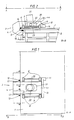
- 1 denotes a sheet which is placed on a horizontal table 2.
- the bending tool 3 is constructed from a U-shaped, relatively wide bracket 4 with a long leg 4a and a short leg 4b, which form an opening 5 between them.
- the tool 3 is provided with two pairs of impellers 6, each on a shaft 7, which are mounted in fork-shaped brackets 8 on the sides of the long leg 4a.
- the shafts 7 are connected to a power transmission arrangement 10 which is driven by a drive motor 11.
- the bracket 4 also has guide rollers 12 rotating about vertically directed axes, which are supported by brackets 13. These guide rollers run on the narrow edge surfaces of the sheet 1.
- An upper ruler 14 and a lower ruler 15 are arranged in the opening 5 of the bracket 1.
- the lower ruler 15 has a greater distance from the bottom of the opening 5 than the upper ruler 14, so that a lever arm L required for bending is formed (FIG. 2).
- the lower ruler 15 can be arranged displaceably with the aid of an actuating cylinder arranged on each side of the bracket 4, as shown in FIG. In this way, the ruler 15 can be moved between the position shown in FIG. 4 and indicated by dash-dotted lines, as a result of which the length of the lever arm L changes.
- the contact surfaces of the two rulers acting as cushions intended for contact with the sheet can expediently be adapted to the desired radius of curvature of the sheet, that is to say the upper, cylindrical concave and the lower, cylindrical convex surface.
- the cushion rulers can be interchangeable for different sheet thicknesses and radii of curvature.
- the cushion rulers are expediently chamfered at the ends (chamfered) so that the ruler ends do not leave any pressure points in the sheet.
- Openings 17 and 18 are provided in leg 4a of bracket 4.
- Cross pieces 20 run in the openings 18, in which a hydraulic cylinder 21 is pivotally mounted with the pin 22.
- the piston rod 23 of the cylinder 21 is directed downward and is pressed against the sheet metal 1 when the piston-cylinder arrangement is actuated.
- the tool 3 is used as follows: It is placed on the sheet 1 so that it engages around a sheet edge.
- the cylinder 21 is actuated, the piston rod 23 pressing against the sheet.
- the tool is tilted from the position shown in FIG. 2 to that shown in FIG. 3, the edge of the sheet 1 being bent by a desired radius by a desired angle.
- Several bends can be carried out with lever arms L of different lengths. The bending can begin at one end of the sheet and can be carried out successively along the entire length of the sheet side by gradually moving the tool along the sheet side, as shown by the dash-dotted line in FIG. 1.
- the step-by-step drawing bends can partially overlap.
- the side shift between two bends can be, for example, 60 to 90% of the tool width.
- the tool is easy to handle and transport and can replace large, expensive stationary press equipment in many cases, especially in small and medium-sized series.
- the legs 4a, 4b of the U-shaped bracket are preferably designed such that their inner sides diverge in the direction of the opening of the U-shaped leg, as can be seen from FIGS. 2 to 4. This widening of the leg distance to the opening of the U-shaped leg makes it easier to place the tool on the edge of the sheet and to use the same tool for sheets of different thicknesses.
Claims (6)
Priority Applications (1)
| Application Number | Priority Date | Filing Date | Title |
|---|---|---|---|
| AT83111121T ATE26933T1 (de) | 1982-11-12 | 1983-11-08 | Verfahren und werkzeug zum biegen von randabschnitten eines bleches. |
Applications Claiming Priority (2)
| Application Number | Priority Date | Filing Date | Title |
|---|---|---|---|
| SE8206438 | 1982-11-12 | ||
| SE8206438A SE443733B (sv) | 1982-11-12 | 1982-11-12 | Sett och verktyg for kantbockning av tjockplat |
Publications (3)
| Publication Number | Publication Date |
|---|---|
| EP0109031A2 EP0109031A2 (fr) | 1984-05-23 |
| EP0109031A3 EP0109031A3 (en) | 1984-09-05 |
| EP0109031B1 true EP0109031B1 (fr) | 1987-05-06 |
Family
ID=20348563
Family Applications (1)
| Application Number | Title | Priority Date | Filing Date |
|---|---|---|---|
| EP83111121A Expired EP0109031B1 (fr) | 1982-11-12 | 1983-11-08 | Procédé et outil pour cintrer les sections marginales d'une tôle |
Country Status (6)
| Country | Link |
|---|---|
| US (1) | US4565084A (fr) |
| EP (1) | EP0109031B1 (fr) |
| JP (1) | JPS59101236A (fr) |
| AT (1) | ATE26933T1 (fr) |
| DE (1) | DE3371296D1 (fr) |
| SE (1) | SE443733B (fr) |
Families Citing this family (5)
| Publication number | Priority date | Publication date | Assignee | Title |
|---|---|---|---|---|
| SE9903143L (sv) * | 1999-09-06 | 2000-06-19 | Stroemsholmen Ab | Anordning vid ett plåtformningsverktyg |
| DE102004050784B3 (de) * | 2004-10-14 | 2006-05-24 | Mannesmannröhren-Werke Ag | Verfahren und Anbiegepresse zum Anbiegen der Randstreifen eines zu einem Schlitzrohr zu formenden ebenen Bleches |
| DE202008000121U1 (de) | 2008-01-03 | 2008-04-17 | Eisenbau Krämer mbH | Blechbiegemaschine |
| IT1391762B1 (it) * | 2008-11-11 | 2012-01-27 | Sms Demag Innse Spa Ora Sms Innse Spa | Pressa piega-bordi |
| CN116765775B (zh) * | 2023-06-28 | 2024-02-20 | 大连福赛汽车部件有限公司 | 一种汽车排气管道固定支架装配工装 |
Family Cites Families (6)
| Publication number | Priority date | Publication date | Assignee | Title |
|---|---|---|---|---|
| US2178926A (en) * | 1937-04-24 | 1939-11-07 | American Steel & Wire Co | Bending machine |
| DE2307134A1 (de) * | 1973-02-14 | 1974-08-22 | Ferndorf Eisen Metall | Vorrichtung zum anbiegen der enden von blechen |
| DE2455596C3 (de) * | 1974-11-23 | 1978-05-03 | Mannesmann Ag, 4000 Duesseldorf | Presse mit Konvex- und Konkavwerkzeug zum Anbiegen der Ränder von Blechen |
| DE2527225C3 (de) * | 1975-06-19 | 1978-10-26 | Walter Eckold Vorrichtungs- Und Geraetebau Sperrluttertal, 3424 St Andreasberg | Vorrichtung zum maßgenauen Abwinkein der Ränder von gewölbten Tankböden |
| FR2331392A1 (fr) * | 1975-11-13 | 1977-06-10 | Charenton Sa Chaudronnerie | Dispositif pour le cambrage des toles a froid |
| DE3011665A1 (de) * | 1980-03-26 | 1981-10-01 | Manfred 4050 Mönchengladbach Lortz | Blechkanten-anbiegepresse |
-
1982
- 1982-11-12 SE SE8206438A patent/SE443733B/sv not_active IP Right Cessation
-
1983
- 1983-11-08 DE DE8383111121T patent/DE3371296D1/de not_active Expired
- 1983-11-08 AT AT83111121T patent/ATE26933T1/de not_active IP Right Cessation
- 1983-11-08 EP EP83111121A patent/EP0109031B1/fr not_active Expired
- 1983-11-09 JP JP58209247A patent/JPS59101236A/ja active Pending
- 1983-11-10 US US06/550,467 patent/US4565084A/en not_active Expired - Fee Related
Also Published As
| Publication number | Publication date |
|---|---|
| SE8206438L (sv) | 1984-05-13 |
| ATE26933T1 (de) | 1987-05-15 |
| US4565084A (en) | 1986-01-21 |
| EP0109031A2 (fr) | 1984-05-23 |
| DE3371296D1 (en) | 1987-06-11 |
| JPS59101236A (ja) | 1984-06-11 |
| EP0109031A3 (en) | 1984-09-05 |
| SE8206438D0 (sv) | 1982-11-12 |
| SE443733B (sv) | 1986-03-10 |
Similar Documents
| Publication | Publication Date | Title |
|---|---|---|
| DE2948115A1 (de) | Verfahren und vorrichtung zum formen von eine naht aufweisenden rohren von bogenfoermigem querschnitt aus flaechigem material, insbesondere blech | |
| EP0226167A2 (fr) | Procédé de pliage de matériau allongé ainsi que machine pour exécuter ce procédé | |
| DE10232098B4 (de) | Vorrichtung zum Herstellen von Rohren aus Blechtafeln | |
| DE102007012316B4 (de) | Verfahren und Anbiegepresse zum Anbiegen der Randstreifen eines zu einem Schlitzrohr zu formenden ebenen Bleches | |
| DE2953278C2 (fr) | ||
| DE2614177A1 (de) | Vorrichtung zum biegen von blechen | |
| EP0109031B1 (fr) | Procédé et outil pour cintrer les sections marginales d'une tôle | |
| EP3144076A1 (fr) | Outil pour une poinçonneuse pour transformer des sections d'une piece usinee en forme de plaque et procede associe | |
| DE2455596C3 (de) | Presse mit Konvex- und Konkavwerkzeug zum Anbiegen der Ränder von Blechen | |
| AT389657B (de) | Verfahren zum biegen von profil- oder wellblechen und vorrichtung zur durchfuehrung des verfahrens | |
| DE3440809A1 (de) | Verfahren und vorrichtung zum verbinden von aufeinanderliegenden blechen durch stanznocken | |
| DE2647550C2 (fr) | ||
| EP0497780B1 (fr) | Procede de cintrage oppose d'une tole | |
| DE2341857C2 (de) | Werkzeuganordnung zur Herstellung von Rohrbogen | |
| DE2418316C2 (de) | Wickelmaschine für Blechbänder | |
| DE2029896C3 (de) | Vorrichtung zum Biegen eines Metallstreifens um einen Dorn, insbesondere beim Herstellen von Spreizhülsen | |
| EP0313760B1 (fr) | Appareil pour fabriquer des poutres de construction ou similaires | |
| DE60120947T2 (de) | Verfahren und vorrichtung zum biegen von blechstreifen mit zwei einander gegenüberliegenden flanschen | |
| DE4030777A1 (de) | Abkantpressen-system mit einer richteinrichtung fuer plattenfoermige werkstuecke | |
| DE2727287A1 (de) | Verfahren und vorrichtung zum biegen profilierter bleche, platten, baender u.dgl. | |
| EP1324841B1 (fr) | Dispositif permettant de plier une bande de matiere | |
| DE1966861C3 (de) | Vorrichtung zur Fertigung eines Formteils mit wellenförmigen Dehnfalten | |
| DE4209259C2 (de) | Biegevorrichtung | |
| DE1926518C3 (de) | Verfahren zum Verformen der längslaufenden Kantenflächen der Seitenbügel für die Glieder einer auf einem Kettenzahnrad arbeitenden Kette | |
| DE1502892B2 (de) | Verfahren zum Kaltformen eines Sägeketten-Schneidgliedes |
Legal Events
| Date | Code | Title | Description |
|---|---|---|---|
| PUAI | Public reference made under article 153(3) epc to a published international application that has entered the european phase |
Free format text: ORIGINAL CODE: 0009012 |
|
| AK | Designated contracting states |
Designated state(s): AT BE CH DE FR IT LI NL |
|
| PUAL | Search report despatched |
Free format text: ORIGINAL CODE: 0009013 |
|
| AK | Designated contracting states |
Designated state(s): AT BE CH DE FR IT LI NL |
|
| 17P | Request for examination filed |
Effective date: 19841120 |
|
| R17P | Request for examination filed (corrected) |
Effective date: 19841120 |
|
| GRAA | (expected) grant |
Free format text: ORIGINAL CODE: 0009210 |
|
| AK | Designated contracting states |
Kind code of ref document: B1 Designated state(s): AT BE CH DE FR IT LI NL |
|
| REF | Corresponds to: |
Ref document number: 26933 Country of ref document: AT Date of ref document: 19870515 Kind code of ref document: T |
|
| REF | Corresponds to: |
Ref document number: 3371296 Country of ref document: DE Date of ref document: 19870611 |
|
| ITF | It: translation for a ep patent filed |
Owner name: JACOBACCI & PERANI S.P.A. |
|
| ET | Fr: translation filed | ||
| PG25 | Lapsed in a contracting state [announced via postgrant information from national office to epo] |
Ref country code: AT Effective date: 19871108 |
|
| PG25 | Lapsed in a contracting state [announced via postgrant information from national office to epo] |
Ref country code: LI Effective date: 19871130 Ref country code: CH Effective date: 19871130 |
|
| PLBE | No opposition filed within time limit |
Free format text: ORIGINAL CODE: 0009261 |
|
| STAA | Information on the status of an ep patent application or granted ep patent |
Free format text: STATUS: NO OPPOSITION FILED WITHIN TIME LIMIT |
|
| 26N | No opposition filed | ||
| PG25 | Lapsed in a contracting state [announced via postgrant information from national office to epo] |
Ref country code: NL Effective date: 19880601 |
|
| NLV4 | Nl: lapsed or anulled due to non-payment of the annual fee | ||
| PG25 | Lapsed in a contracting state [announced via postgrant information from national office to epo] |
Ref country code: FR Free format text: LAPSE BECAUSE OF NON-PAYMENT OF DUE FEES Effective date: 19880729 |
|
| REG | Reference to a national code |
Ref country code: CH Ref legal event code: PL |
|
| PG25 | Lapsed in a contracting state [announced via postgrant information from national office to epo] |
Ref country code: DE Effective date: 19880802 |
|
| REG | Reference to a national code |
Ref country code: FR Ref legal event code: ST |
|
| PG25 | Lapsed in a contracting state [announced via postgrant information from national office to epo] |
Ref country code: BE Effective date: 19881130 |
|
| BERE | Be: lapsed |
Owner name: ASEA A.B. Effective date: 19881130 |