EP0108049B1 - Dispositif de support des billes dans une scie a chassis - Google Patents
Dispositif de support des billes dans une scie a chassis Download PDFInfo
- Publication number
- EP0108049B1 EP0108049B1 EP82901446A EP82901446A EP0108049B1 EP 0108049 B1 EP0108049 B1 EP 0108049B1 EP 82901446 A EP82901446 A EP 82901446A EP 82901446 A EP82901446 A EP 82901446A EP 0108049 B1 EP0108049 B1 EP 0108049B1
- Authority
- EP
- European Patent Office
- Prior art keywords
- log
- support device
- supporting
- elements
- saw
- Prior art date
- Legal status (The legal status is an assumption and is not a legal conclusion. Google has not performed a legal analysis and makes no representation as to the accuracy of the status listed.)
- Expired
Links
Images

Classifications
-
- B—PERFORMING OPERATIONS; TRANSPORTING
- B27—WORKING OR PRESERVING WOOD OR SIMILAR MATERIAL; NAILING OR STAPLING MACHINES IN GENERAL
- B27B—SAWS FOR WOOD OR SIMILAR MATERIAL; COMPONENTS OR ACCESSORIES THEREFOR
- B27B3/00—Gang saw mills; Other sawing machines with reciprocating saw blades, specially designed for length sawing of trunks
- B27B3/02—Gang saw mills; Other sawing machines with reciprocating saw blades, specially designed for length sawing of trunks with vertically-reciprocating saw frame
- B27B3/14—Arrangements for raising or lowering the feed rollers
-
- B—PERFORMING OPERATIONS; TRANSPORTING
- B27—WORKING OR PRESERVING WOOD OR SIMILAR MATERIAL; NAILING OR STAPLING MACHINES IN GENERAL
- B27B—SAWS FOR WOOD OR SIMILAR MATERIAL; COMPONENTS OR ACCESSORIES THEREFOR
- B27B25/00—Feeding devices for timber in saw mills or sawing machines; Feeding devices for trees
Definitions
- the present invention relates to a support device for supporting a log advancing through a frame saw, said device comprising one or more supporting elements positioned adjacent to the saw frame.
- Frame saws represent the oldest known sawing technique for mechanically ripping round logs into various types of sawn timber.
- the frame saws in principle consist of a frame which is guided for reciprocating movement in a plane, preferably in a vertical direction.
- the frame may be guided by means such as rollers, slides etc., and the movement may be provided by means of various mechanical systems of which the most usual comprises a crank shaft with a connecting rod.
- One or more parallel saw blades are strapped in the frame, and the log to be ripped is advanced towards the frame and the saw blades.
- the reciprocating saw blades will cut the log and rip it into a plurality of planks, boards, blocks etc. according to the size and shape of the log and the positioning of the saw blade in the frame.
- the log is advanced towards the saw blades in a stable and linear fashion.
- This can be obtained by fixing one or both ends of the log in a trolley accompanying the log during the advancement thereof and preventing the log from rolling laterally or twisting.
- the log is usually fixed and supported by a plurality of rollers under, above and possibly also at the sides of the log immediately in front or upstream of the saw frame. These rollers will support the log adjacent the frame and are primarily intended to take up the reaction forces from the sawing operation.
- the rollers may also be rotationally driven and thereby provide the necessary force for advancing the log.
- the advancement or feeding of the log can be obtained by a winch or the like pulling the log through the saw.
- strong driving blades are often provided behind the saw blades.
- An object of the present invention is to stabilize a nonuniform log having lopped-off twigs in a manner allowing for irregularities in the log, while providing a fixed, rigid support capable of taking up the forces from the saw blades.
- This object is met according to the present invention by providing supporting elements adapted to be resiliently pressed into contact with the log with a predetermined force, and to be locked for fixedly supporting the log and taking up the forces from the saw blades during the entire working stroke thereof, said elements being releasable during at least a part of the return stroke to allow the elements to adapt themselves to the varying shape of the advancing log.
- the force with which the elements are pressed into contact with the log in released condition is adjustable in accordance with the weight and shape of the log.
- Each supporting element may be associated with an hydraulic system pressing the element into contact with the log.
- each supporting element may be associated with a mechanical device providing the force pressing the element into contact with the log.
- the supporting element may be blocked during the working stroke by mechanical means such as wedges, stepped stops or brakes.
- the locking of the supporting elements may be achieved by means of a valve which when closed blocks the flow of hydraulic medium, thereby locking the supporting elements. When the valve is open the supporting element is released. Further supporting elements may be arranged over the length of the log path.
- Such supporting elements are preferably lockable like the previously defined supporting elements. However, such locking may not be necessary in connection with supporting elements positioned at a substantial distance from the saw frame.
- the supporting elements may consist of rollers or wheels, and in this case one or more of the rollers or wheels may be rotatably driven to provide the feeding movement of the log.
- the supporting elements are fixed and will not yield, so that they may take up the reaction forces from the sawing operation.
- the supporting elements are released and may then freely adapt themselves to the shape of the log by being forced into contact therewith by the hydraulic or mechanical means referred to.
- the supporting elements are locked in position to effectively support the log during the cutting operation.
- the system will operate particularly effectively if the known technique comprising a mounting of the saw blades with a suitable inclination relative to the path of reciprocation is used.
- the log may be halted during the working stroke and be advanced only during the return stroke. This will provide the greatest precision of the sawing operation.
- the described device while easily adapting itself even to large irregularities and bends of the log, will at the same time provide a stable fixation of the log during the sawing operation without any tendency of yielding or twisting under the effect of the relatively large reaction forces from the cutting operation of the saw blades.
- Even very nonuniform logs can be easily advanced and fixedly supported in the frame saw without resulting defects in the sawn timber.
- BY concentrating the feeding to the return stroke the largest possible precision will be obtained, since the log will be supported in a stable and fixed manner during the sawing operation.
- power is saved since the advancement of the log will take place against unstressed saw blades during the return stroke, provided the saw blades are inclined as referred to above, so that they are not in contact with the bottom of the kerf during the return stroke.
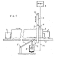
- Figure 1 the round log 1 to be cut is advanced to the right as indicated by an arrow.
- a saw frame 3 is mounted for reciprocal movement up and down.
- the guides and the operating system for the frame are not illustrated since they may be conventional.
- a plurality of parallel saw blades are strapped in the frame in a conventional manner.
- the log 1 is advanced against and through the saw frame, while being supported at the ends on two trolleys 2 running on rails 11.
- the trolleys 2 are designed to allow the log 1 to be "fetched” and “delivered” through the saw frame past the saw blades without the trolley itself having to pass through the frame.
- the advancement or feed may be obtained by means of a winch (not shown) pulling the rear trolley forwards.
- a supporting element in the form of a roller 4 which is mounted at the end of a one-armed lever 13 mounted on a pivot 6.
- the roller 4 is pressed into contact with the log 1 by a piston 12 of an hydraulic piston-cylinder unit 5.
- Hydraulic liquid under pressure acts on one side of the piston 12 in order to raise the roller 4 and press it into good contact with the log 1.
- the pressure of the hydraulic liquid may be obtained by means of an hydraulic liquid tank 7 positioned at a high level and communicating with the cylinder through a conduit 14.
- a valve 8 which may be actuated by cams or dogs 9 and 10 on the saw frame 3.
- the cam 10 will open the valve 8 when the saw frame 3 arrives at its lower dead point, and the valve will be closed by the cam 9 when the saw frame arrives at its higher dead point.
- the valve 8 will remain closed. Because of the low compressibility of the hydraulic liquid the piston 12 and the roller 4 cannot move up or down, but remains in a fixed position even if the downwardly directed reaction forces from the saw blades are large.
- the valve 8 is opened by the cam 10 and remains open during the return movement of the frame.
- the pressure of the hydraulic liquid in the cylinder 5 may be provided in any suitable manner.
- pressure can be imparted to the hydraulic liquid in a closed tank by means of a gas cushion, a spring or weight loaded piston or the like.
- the valve 8 may alternatively be controlled by the operating mechanism for the saw frame through cams or by transmission of electromagnetic impulses. It is essential for a proper functioning of the device that the valve 8 is kept closed during the working stroke, so that the roller 4 is fixed and can take up the reaction forces from the saw blades in the frame 3, which forces will act on the log 1 in the direction of movement of the saw frame during the working stroke.
- the feeding means for advancing the log through the saw frame must be open during the return stroke for a sufficient period to release the roller and allow it to adapt itself to the shape of the log during, advancement thereof. It is especially advantageous for the feeding means for advancing the log through the saw frame to be synchronized with the stroke of the saw frame, so as to be operative only when the supporting elements are released, the feeding being interrupted during the working stroke.
- the system is provided with a closed tank having a pressure control, for instance in the form of a gas cushion, the pressure can be varied simply by increasing or reducing the pressure of the gas cushion, for instance by means of a compressor and a relief valve, respectively.
- FIG 2 a mechanical system is shown strictly diagrammatically.
- the reference numerals 1, 2, 3 and 11 designate the same elements as in the embodiment in Figure 1.
- the saw frame 3 is driven by a connecting rod 16 connected to a crankshaft having a flywheel 15.
- the supporting element may be a roller as in Figure 1, but the element 17 shown in Figure 2 is a plate with a curved upper side.
- the supporting element 17 is provided with a stem 18 guided for vertical reciprocal movement in a suitable guide 19. Through a two-armed lever 21 a weight 20 acts on the stem 18 to press the supporting element 17 into contact with the log 1.
- a “wedge” or stepped stop 26 is mounted at the end of a two-armed lever 24, and is biassed to a position below the lower end 27 of the stem 18 by means of a spring 25.
- a cam follower 23 At the other end of the two-armed lever 24 there is mounted a cam follower 23 which engages a cam surface 22 on the circumference of the flywheel 15.
- the cam surface 22 engages the cam follower 23
- the stepped stop or "wedge” 26 will be retracted from the position below the lower end of the stem 18, as illustrated in Figure 2.
- the crankshaft rotates as indicated by the arrow 28, the "wedge” 26 will be retracted from the stem 18 when the saw frame 3 is moving upwards, i.e. during the return stroke.
- the supporting element 17 will then be freely movable in the guide 19, following the shape of the log 1 under the influence of the weight 20.
- the saw frame 3 is moving downwards during its working stroke, there is no cam surface to influence the lever 24 through the cam follower 23, and the "wedge" 26 will then be pulled by the spring 25 to a position below the stem 18.
- the log 1 will then be rigidly supported by the supporting element 17, except for a possible small downward movement which cannot exceed the pitch of the stepped stop 26.
- the log 1 is advanced only during the return strokes of the saw frame 3.
- the log may be advanced by means of a feeding device, which is not illustrated since it may be of a conventional type.
Landscapes
- Life Sciences & Earth Sciences (AREA)
- Engineering & Computer Science (AREA)
- Mechanical Engineering (AREA)
- Wood Science & Technology (AREA)
- Forests & Forestry (AREA)
- Sawing (AREA)
- Audible-Bandwidth Dynamoelectric Transducers Other Than Pickups (AREA)
- Mushroom Cultivation (AREA)
- Load-Engaging Elements For Cranes (AREA)
- Soil Working Implements (AREA)
- Ladders (AREA)
Claims (10)
Priority Applications (1)
| Application Number | Priority Date | Filing Date | Title |
|---|---|---|---|
| AT82901446T ATE19019T1 (de) | 1982-05-12 | 1982-05-12 | Tragvorrichtung fuer baumstaemme in einer gattersaege. |
Applications Claiming Priority (1)
| Application Number | Priority Date | Filing Date | Title |
|---|---|---|---|
| PCT/NO1982/000027 WO1983003996A1 (fr) | 1982-05-12 | 1982-05-12 | Dispositif de support des billes dans une scie a chassis |
Publications (2)
| Publication Number | Publication Date |
|---|---|
| EP0108049A1 EP0108049A1 (fr) | 1984-05-16 |
| EP0108049B1 true EP0108049B1 (fr) | 1986-04-09 |
Family
ID=19907188
Family Applications (1)
| Application Number | Title | Priority Date | Filing Date |
|---|---|---|---|
| EP82901446A Expired EP0108049B1 (fr) | 1982-05-12 | 1982-05-12 | Dispositif de support des billes dans une scie a chassis |
Country Status (6)
| Country | Link |
|---|---|
| EP (1) | EP0108049B1 (fr) |
| AT (1) | ATE19019T1 (fr) |
| AU (1) | AU8397182A (fr) |
| DE (1) | DE3270362D1 (fr) |
| DK (1) | DK150730C (fr) |
| WO (1) | WO1983003996A1 (fr) |
Families Citing this family (1)
| Publication number | Priority date | Publication date | Assignee | Title |
|---|---|---|---|---|
| SE465156B (sv) * | 1990-04-17 | 1991-08-05 | Vislanda Saagverksmaskiner Ab | Instaellningsanordning vid en anlaeggning foer framdrivning av stockar |
Family Cites Families (6)
| Publication number | Priority date | Publication date | Assignee | Title |
|---|---|---|---|---|
| SE10397C1 (fr) * | 1899-12-02 | |||
| DE362791C (de) * | 1922-11-01 | Wilhelm Hofmann | Vertikalgatter | |
| DE258119C (fr) * | ||||
| DE346512C (de) * | 1915-12-11 | 1922-01-02 | Wilhelm Hofmann | Vorrichtung zum mechanischen Bewegen der Druckwalzen an Gattersaegen |
| DE523722C (de) * | 1928-03-17 | 1931-06-20 | Adolf Mueller | Gattersaege |
| DE1033399B (de) * | 1954-01-04 | 1958-07-03 | Soederhamns Verkstaeder Aktieb | Gattersaegemaschine |
-
1982
- 1982-05-12 WO PCT/NO1982/000027 patent/WO1983003996A1/fr active IP Right Grant
- 1982-05-12 AU AU83971/82A patent/AU8397182A/en not_active Abandoned
- 1982-05-12 EP EP82901446A patent/EP0108049B1/fr not_active Expired
- 1982-05-12 AT AT82901446T patent/ATE19019T1/de not_active IP Right Cessation
- 1982-05-12 DE DE8282901446T patent/DE3270362D1/de not_active Expired
-
1984
- 1984-01-11 DK DK012284A patent/DK150730C/da not_active IP Right Cessation
Also Published As
| Publication number | Publication date |
|---|---|
| EP0108049A1 (fr) | 1984-05-16 |
| DK12284A (da) | 1984-01-11 |
| ATE19019T1 (de) | 1986-04-15 |
| WO1983003996A1 (fr) | 1983-11-24 |
| DK150730B (da) | 1987-06-09 |
| DK12284D0 (da) | 1984-01-11 |
| DE3270362D1 (en) | 1986-05-15 |
| DK150730C (da) | 1987-12-21 |
| AU8397182A (en) | 1983-12-02 |
Similar Documents
| Publication | Publication Date | Title |
|---|---|---|
| US4175452A (en) | Machine for the mechanical working of band saws | |
| CN207840260U (zh) | 液压闸式剪板机 | |
| CN211135700U (zh) | 一种金属板材定长剪切装置 | |
| US4702137A (en) | Automatic band-saw system | |
| CA1230036A (fr) | Installation pour la production du bois d'oeuvre equarri par refendage en planches nettes sans sciure ni copeaux | |
| US3678792A (en) | Metal plate shears | |
| CN110899575B (zh) | 一种钢筋切断机 | |
| CN110815397A (zh) | 一种自动进料的原木切割用双锯片切割设备及其工作方式 | |
| CN212885382U (zh) | 一种剪板机 | |
| EP0108049B1 (fr) | Dispositif de support des billes dans une scie a chassis | |
| KR100917578B1 (ko) | 절단기 | |
| US2642910A (en) | Carriage control device for bacon slicing machines | |
| US3295569A (en) | Machine for cutting wood with a fixed blade | |
| US3044336A (en) | Cutting devices for moving oblong works | |
| CN116921549A (zh) | 集水盘冲压生产设备 | |
| IE52845B1 (en) | Support device for logs in a frame saw | |
| CN212533496U (zh) | 一种杯型口罩切割装置 | |
| CN115138750A (zh) | 一种角钢切断设备 | |
| US3176559A (en) | Indexing device for squaring shear | |
| CN209774301U (zh) | 一种全自动管件切割装置 | |
| CA1185146A (fr) | Support de grumes sur scie mecanique alternative | |
| GB1132341A (en) | Improvements in or relating to guillotines | |
| US3608594A (en) | Cutting or trimming device for veneered workpieces | |
| US2791823A (en) | Rod-sawing machine | |
| US4457198A (en) | Apparatus for cutting lengths of lumber into blocks |
Legal Events
| Date | Code | Title | Description |
|---|---|---|---|
| PUAI | Public reference made under article 153(3) epc to a published international application that has entered the european phase |
Free format text: ORIGINAL CODE: 0009012 |
|
| AK | Designated contracting states |
Kind code of ref document: A1 Designated state(s): AT BE CH DE FR GB LI LU NL SE |
|
| 17P | Request for examination filed |
Effective date: 19840424 |
|
| GRAA | (expected) grant |
Free format text: ORIGINAL CODE: 0009210 |
|
| AK | Designated contracting states |
Kind code of ref document: B1 Designated state(s): AT BE CH DE FR GB LI LU NL SE |
|
| PG25 | Lapsed in a contracting state [announced via postgrant information from national office to epo] |
Ref country code: NL Effective date: 19860409 Ref country code: LI Effective date: 19860409 Ref country code: FR Free format text: THE PATENT HAS BEEN ANNULLED BY A DECISION OF A NATIONAL AUTHORITY Effective date: 19860409 Ref country code: CH Effective date: 19860409 Ref country code: BE Effective date: 19860409 Ref country code: AT Effective date: 19860409 |
|
| REF | Corresponds to: |
Ref document number: 19019 Country of ref document: AT Date of ref document: 19860415 Kind code of ref document: T |
|
| REF | Corresponds to: |
Ref document number: 3270362 Country of ref document: DE Date of ref document: 19860515 |
|
| PG25 | Lapsed in a contracting state [announced via postgrant information from national office to epo] |
Ref country code: LU Free format text: LAPSE BECAUSE OF NON-PAYMENT OF DUE FEES Effective date: 19860531 |
|
| REG | Reference to a national code |
Ref country code: CH Ref legal event code: PL |
|
| EN | Fr: translation not filed | ||
| NLV1 | Nl: lapsed or annulled due to failure to fulfill the requirements of art. 29p and 29m of the patents act | ||
| PG25 | Lapsed in a contracting state [announced via postgrant information from national office to epo] |
Ref country code: DE Effective date: 19870203 |
|
| PLBE | No opposition filed within time limit |
Free format text: ORIGINAL CODE: 0009261 |
|
| STAA | Information on the status of an ep patent application or granted ep patent |
Free format text: STATUS: NO OPPOSITION FILED WITHIN TIME LIMIT |
|
| 26N | No opposition filed | ||
| PGFP | Annual fee paid to national office [announced via postgrant information from national office to epo] |
Ref country code: SE Payment date: 19900406 Year of fee payment: 9 |
|
| PGFP | Annual fee paid to national office [announced via postgrant information from national office to epo] |
Ref country code: GB Payment date: 19900424 Year of fee payment: 9 |
|
| PG25 | Lapsed in a contracting state [announced via postgrant information from national office to epo] |
Ref country code: GB Effective date: 19910512 |
|
| PG25 | Lapsed in a contracting state [announced via postgrant information from national office to epo] |
Ref country code: SE Effective date: 19910513 |
|
| GBPC | Gb: european patent ceased through non-payment of renewal fee | ||
| EUG | Se: european patent has lapsed |
Ref document number: 82901446.3 Effective date: 19911209 |