EP0106321A2 - Tête magnétique amorphe et procédé de fabrication - Google Patents
Tête magnétique amorphe et procédé de fabrication Download PDFInfo
- Publication number
- EP0106321A2 EP0106321A2 EP83110220A EP83110220A EP0106321A2 EP 0106321 A2 EP0106321 A2 EP 0106321A2 EP 83110220 A EP83110220 A EP 83110220A EP 83110220 A EP83110220 A EP 83110220A EP 0106321 A2 EP0106321 A2 EP 0106321A2
- Authority
- EP
- European Patent Office
- Prior art keywords
- core halves
- magnetic head
- amorphous magnetic
- reinforcing members
- core
- Prior art date
- Legal status (The legal status is an assumption and is not a legal conclusion. Google has not performed a legal analysis and makes no representation as to the accuracy of the status listed.)
- Granted
Links
Images


Classifications
-
- G—PHYSICS
- G11—INFORMATION STORAGE
- G11B—INFORMATION STORAGE BASED ON RELATIVE MOVEMENT BETWEEN RECORD CARRIER AND TRANSDUCER
- G11B5/00—Recording by magnetisation or demagnetisation of a record carrier; Reproducing by magnetic means; Record carriers therefor
- G11B5/127—Structure or manufacture of heads, e.g. inductive
- G11B5/147—Structure or manufacture of heads, e.g. inductive with cores being composed of metal sheets, i.e. laminated cores with cores composed of isolated magnetic layers, e.g. sheets
- G11B5/1475—Assembling or shaping of elements
-
- G—PHYSICS
- G11—INFORMATION STORAGE
- G11B—INFORMATION STORAGE BASED ON RELATIVE MOVEMENT BETWEEN RECORD CARRIER AND TRANSDUCER
- G11B5/00—Recording by magnetisation or demagnetisation of a record carrier; Reproducing by magnetic means; Record carriers therefor
- G11B5/10—Structure or manufacture of housings or shields for heads
-
- G—PHYSICS
- G11—INFORMATION STORAGE
- G11B—INFORMATION STORAGE BASED ON RELATIVE MOVEMENT BETWEEN RECORD CARRIER AND TRANSDUCER
- G11B5/00—Recording by magnetisation or demagnetisation of a record carrier; Reproducing by magnetic means; Record carriers therefor
- G11B5/127—Structure or manufacture of heads, e.g. inductive
- G11B5/147—Structure or manufacture of heads, e.g. inductive with cores being composed of metal sheets, i.e. laminated cores with cores composed of isolated magnetic layers, e.g. sheets
Definitions
- the present invention generally relates to a head for recording a signal containing a high frequency component as in a television signal, onto a recording medium having a high coercive force or for reproducing such a signal therefrom, and more particularly, to an amorphous magnetic head in which a main core is composed of an amorphous magnetic material and also, to a manufacturing method of such an amorphous magnetic head in an efficient manner.
- ferrite single crystal material is employed for a main core, because said material is superior in abrasion resistance, with favorable soft magnetic characteristics.
- a material such as a metal tape and the like having a high coercive force and capable of achieving recording at a higher density is employed also for a magnetic tape, for example, as in the so-called 8mm movie camera type video tape recorders.
- the sendust heads as referred to above have various disadvantages for the heads of video tape recorders to be - used in a higher frequency range (e.g. 5 MHZ or thereabout)' in that machining thereof is difficult, while due to a low electrical resistance as compared with the ferrite material, the sendust heads have a large eddy current loss at high frequency range, with a sharp reduction of the effective permeability, and thus, the sendust heads have not been supplied as yet into the market for the heads of video tape recorders currently available.
- a higher frequency range e.g. 5 MHZ or thereabout
- the amorphous material is obtained by a manufacturing method referred to as a liquid melt rapid cooling method, in which an amorphous material having an alloy composition not conceivable by the conventional knowledge of metallurgy may be produced in terms of principle.
- a liquid melt rapid cooling method in which an amorphous material having an alloy composition not conceivable by the conventional knowledge of metallurgy may be produced in terms of principle.
- the configurations of the material to be produced by the above manufacturing method More specifically, since it is required to rapidly cool the molten metal at cooling speeds of 100,000 to 1,000,000°C/sec., the resultant amorphous material is obtainable only in the form of a ribbon-like sheet of 10 to 100 microns in thickness or in the form of a powder.
- the manufacturing method conventionally adopted for the ferrite material i.e., the processing technique such as cutting, polishing, welding, etc. from a bulk material.
- the conventional manufacturing method as described above it may be considered to employ a starting material prepared by laminating a large number of ribbon-like sheets one upon another (i.e., forming such ribbon-like sheets into a shape similar to the bulk material), thereby to constitute a magnetic head with a track width less than a thickness of the ribbon-like sheet, but since precise control of a thickness of a bonding material layer between the ribbon-like sheets can not be readily effected, it is extremely difficult to arrange the confronting core halves to face each other precisely.
- amorphous materials prepared by the rapid cooling method have transition points of crystalline structure referred to as vitrification temperature Tg and cyrstallization temperature Tx.
- the vitrification temperature is a temperature at which the amorphous material begins to be softened in the similar manner as in the common soda-lime glass, silica glass, etc.
- the crystallization temperature is a temperature at which the amorphous structure is transferred to the crystalline structure. It is to be noted here that, different from glass in general, the amorphous material is not provided with reversibility during passing of the above transition points.
- an essential object of the present invention is to provide a magnetic head having a main core made of a thin sheet of an amorphous magnetic material, i.e., an amorphous magnetic head, which is capable of efficiently recording high frequency signals such as video signals, etc. on a high coercive tape such as a metal tape, with a simultaneous prolongation of life.
- Another important object of the present invention is to provide an amorphous magnetic head of the above described type, which is stable in functioning at high reliability, and can be readily manufactured at low cost.
- a further object of the present invention is to provide a method of manufacturing an amorphous magnetic head of the above described type in an efficient manner on a large scale.
- an amorphous magnetic head which includes a main core having core halves each formed - from non-laminated thin sheets of amorphous magnetic material, a non-magnetic spacer, said core halves being abutted against each other through the non-magnetic spacer disposed in a front gap which is provided between said core halves and whose lower edge is defined by a coil winding opening formed in the core halves, and a set of reinforcing members applied onto opposite sides of the main core to hold the core halves therebetween, with resinous material being filled between the respective reinforcing members and the core halves for integration of the respective elements into one unit.
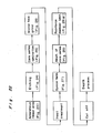
- the amorphous magnetic head of the present invention as described above may be produced by a manufacturing method which includes the steps of constituting a set of core halves each having a coil winding opening which defines a lower edge'of a front gap at least in one of abutted faces thereof through processing of thin sheets of amorphous magnetic material without lamination thereof, arranging the core halves to be abutted against each other through a non-magnetic spacer disposed at the front gap between said core halves, holding the core halves thus abutted against each other between a set of reinforcing members, and filling resinous material through penetration between the core halves and the reinforcing members under a state where both of said core halves are depressed from all directions, i.e., both vertically and laterally, for subsequent heating and curing of the resinous material, thereby to integrate the respective elements into one unit.
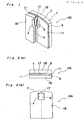
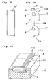
- the magnetic head HA generally comprises a main core c which includes core halves 11 abutted against each other and each formed by shaping a non-laminated thin plate or sheet (24 microns in thickness) of an amorphous magnetic material, a pair of reinforcing members 18 for holding the main core c therebetween, and layers b of a bonding material (less than 2 microns in thickness) each applied between the main core c and the reinforcing member 18 so as to be cured or hardened.
- a main core c which includes core halves 11 abutted against each other and each formed by shaping a non-laminated thin plate or sheet (24 microns in thickness) of an amorphous magnetic material, a pair of reinforcing members 18 for holding the main core c therebetween, and layers b of a bonding material (less than 2 microns in thickness) each applied between the main core c and the reinforcing member 18 so as to be cured or hardened.
- Each of the core halves 11 is formed with a notch or groove g as a coil winding opening between the abutted faces thereof, while a spacer 17 of a non-magnetic material for forming a front gap is provided at the upper portion of the groove g.
- Each of the reinforcing members 18 made, for example, of glass material is formed with a through-hole o in a position corresponding to the groove g or coil winding opening of the main core c so as to make it possible to effect, the so-called balance winding of the coils (not particularly shown) therethrough.
- the magnetic head HA is ground for providing a predetermined radius of curvature on its contact face f confronting a magnetic tape (not shown) so as to achieve a proper matching with respect to the magnetic tape during running of said magnetic tape.
- the magnetic head HA is extremely small in size with dimensions of about 3 mm square and several hundred microns in thickness
- the side faces of the reinforcing members 18 are connected to a head base (not particularly shown), with the contact face f of the head HA being projected from said head base for easiness in handling.
- the magnetic head HA according to the present invention which is formed by arranging the core halves 11 made of non-laminated thin sheets of the amorphous magnetic material to be abutted against each other, and applying the reinforcing members 18 of glass material to opposite sides of the core halves 11, with infiltration of resin or bonding agent b therebetween for the formation of the entire structure into one unit, can be manufactured at a high yield.
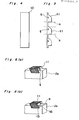
- a thin sheet or ribbon 10 of the amorphous material approximately 24 microns or so in thickness is prepared by the liquid melt rapid cooling method as described earlier (Fig. 4), and a series of core halves 11 of a required shape are formed in the above ribbon 10 by a chemical etching (Fig. 5), with a through-opening for the groove g being formed in each of the core halves 11 for winding the coil therethrough.
- the series of core halves 11 thus prepared are cut off along dotted lines n to obtain a large number of core halves or core chips 11. As shown in Figs.
- the core chips 11 are accommodated in a jig Ja so that the through-openings are arranged in a forward position at one side, and in a rearward position at the other side, and are first subjected to rough grinding so as to remove sagging and the like by the etching for setting the core halves 11 into the predetermined dimensions. Subsequently, the front gap forming face of the magnetic head is ground through employment of very fine grinding grains and a grinding machine.
- Figs. 7(a) and 7(b) show the states upon termination of the above grinding.
- an angle 16 for accommodating the core halves 11 with respect to a wall surface 15 of the jig Ja (Fig. 6(b)) is arranged to coincide with an azimuth angle of the magnetic head.
- the core chips 11 ground as described above are detached from the jig Ja for a heat treatment, which is intended to remove stresses due to the rapid cooling and mechanical processing during manufacture of the amorphous material, and also, to eliminate a grinding strain imparted during the above grinding process.
- a heat treatment which is intended to remove stresses due to the rapid cooling and mechanical processing during manufacture of the amorphous material, and also, to eliminate a grinding strain imparted during the above grinding process.
- the permeability of cores may be improved, because a weak magnetic anisotropy actually remains in the lengthwise and widthwise directions of the ribbon of amorphous material due to temperature gradient and mechanical stress during the rapid cooling of the ribbon, although the amorphous material having no crystalline structure should normally be free from crystalline anisotropy in terms of principle.
- the amorphous material employed is of metal metalloid series (75% of Fe, Co series, 25% of semi-metals such as Si, B, P and C), with Curie temperature Tc at 450°. and crystallization temperature Tx at approximately 500°C, the temperature is raised to the vicinity of a point below Curie temperature Tc and the heat treatment is effected in the magnetic field (especially, rotating magnetic field).
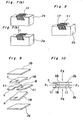
- the large number of core chips 11 are again laminated within the jig Ja, and a spacer 17 of non-magnetic material such as SiO 2 , TiN, SiN, WN or the like is formed on the surface equivalent to the front gap by a predetermined gap length (for example, 0.4 to 0.05 micron) through vapor deposition or ion plating. It may be so arranged that the predetermined gap length is covered through combination with other core halves.
- a predetermined gap length for example, 0.4 to 0.05 micron
- a set of core halves 11 and separately prepared reinforcing members 18 of glass material are disposed between sheets Jb, for example, of Teflon as a jig, and the core halves 11 are depressed from opposite sides by forces Fl of 10 to 100 grams as shown in Fig. 10, while the whole structure is vertically depressed by forces F2 through the sheets Jb.
- sheets Jb for example, of Teflon as a jig
- forces Fl of 10 to 100 grams as shown in Fig. 10
- F2 through the sheets Jb.
- each of the core halves 11 is arranged to laterally project from the reinforcing member 18 to a certain extent.
- the whole structure of the magnetic head is impregnated with epoxy resin in the vacuum state, with a subsequent hardening or curing through heating (by leaving to stand at a temperature of 100°C for 60 to 90 minutes), and thus, the reinforcing members 18 and core halves 11 are combined into one unit together with the depressing jig Jc between the sheets Jb as shown in Fig. 11.
- the structure thus combined is released from the sheets Jb and jig Jc (Figs. 12(a) and 12(b)) and is properly shaped for its tape contacting face or the like with further provision of coils, etc., and thus, the magnetic head as shown in Fig. 1 is obtained.
- the material for the sheets Jb is not limited to ethylene tetrafluoride or trifluoride (e.g. Teflon) as described above, but may be replaced by any material such as polyethylene, polypropylene or the like so far as it can be utilized as a solid releasing material to which epoxy resin does not adhere.
- releasing material in a liquid form is not suitable for the purpose, since it tends to penetrate into gap portions of the head or between the reinforcing members and cores for undesirable reduction of the bonding strength therebetween.
- the reinforcing members 18 are constituted by a dense material of a non-magnetic and non-conductive nature such as ceramics, etc. besides glass as described earlier, because a sintered material having air bubbles or voids therein tend to be subjected to clogging by the magnetic particles from the magnetic tape, thus resulting in an increased spacing loss.
- Forming the reinforcing members 18 by a metallic material is not preferable, since recording efficiency is extremely reduced by an anti-magnetic field produced in the metallic reinforcing members during the recording, but is suitable for a magnetic head exclusive for reproduction, because such metallic reinforcing members function to improve reproducing efficiency during the reproduction.
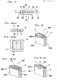
- FIG. 13 there are shown modifications of the magnetic head HA as described so far.
- the reinforcing members 18B made of a metallic material has coil winding portions 18B-1 of non-metallic material as indicated by hatchings
- the reinforcing members 18C made of a metallic material also have coil winding portions 18C-1 of non-metallic material as shown by hatchings.
- the magnetic heads HB, and HC of the above described type may be used as heads both for recording and reproduction.
- FIG. 13 In another modified magnetic head HC' in Fig.
- the reinforcing members 18C' are made of a magnetic ferrite material, while the portion 18C'-1, at least corresponding to the spacer 17 should be made of a non-magnetic material, for example, glass in order to prevent magnetic shortcircuiting.
- a non-magnetic material for example, glass
- the reinforcing members are constructed in the manner as described above with reference to Figs. 13., 14(a) or 14 (b), the reproduction output of the magnetic head can be readily improved. Since other constructions and effects of the magnetic heads HB, HC and HC' are generally similar to those of the magnetic head HA of Fig. 1, detailed description thereof is abbreviated for brevity.
- the present invention it is so arranged that core halves formed into the predetermined shape from the amorphous magnetic thin material manufactured by the liquid melt rapid cooling method, without fundamentally effecting the processing in the direction of thickness of said amorphous material, are abutted against each other, while the reinforcing members are further applied to the core halves from opposite sides thereof, with resin being filled therebetween to be hardened for integration of the magnetic head structure, and therefore, magnetic heads for high frequency range having the main cores of amorphous magnetic material superior in magnetic characteristics may be manufactured at a favorable yield in production.
- a modified method of manufacturing an amorphous magnetic head In this modification, the jigs Jb and Jc, etc. described as employed for keeping the core halves 11 in pressure contact with each other together with the reinforcing members 18 for the formation of the head gap in the foregoing embodiments are replaced by a resilient spring frame S made, for example, of non-magnetic metal or resinous material, and formed by chemical etching or blanking through processing by a machine to have a size just sufficient to accommodate therein an assembly of the core halves 11 and reinforcing members 18.
- the resilient spring frame S is provided with side portions S-1 having projections p for depressing the core halves 11.
- the frame S is fitted around the assembly including the core halves 11 abutted against each other through the non-magnetic spacer 17 and held between the reinforcing members 18 as described previously, with the bonding material b' being applied between the side edges of said assembly and the inner edges of the frame S, whereby the core halves 11 are pressed against each other at the projections p by the spring force of the side portions S-1 in the directions shown by arrows to provide the amorphous magnetic head HD as shown in Fig. 16.
- the frame S After completion of the assembling of the magnetic head, the frame S may be removed from the magnetic head or left as it is on the magnetic head depending on necessity.
- the jigs required for the manufacture of the amorphous magnetic heads may be dispensed with for the simplification of the manufacturing _ process.
- the frame SB made, for example, of a metallic material having a resiliency such as phosphor bronze, stainless steel, etc. has its one side portion SB-1 cut off at one end and provided with a projection p so as to act as a spring for effecting abutting of the core halves 11 (i.e. formation of the head gap) by the resilient restoring force of said side portion SB-1.
- the frame SB may be removed or left as it is after completion of the magnetic head, but if the frame SB is to be left on the magnetic head as in the arrangement of Fig. 16, non-magnetic material should be used for the frame SB.
- the frame SC with a continuous side portions has a protrusion pc formed in one side portion SC-1 thereof as shown.
- the frame SC is fitted around the assembly including the core halves 11 and the reinforcing members 18, and the protrusion pc is pushed inwardly in a direction indicated by an arrow in Fig. 18 by a depressing plate Ta, with the frame SC being supported at the other side by a support plate Tb for abutting the core halves 11 against each other by depressing one of the core halves 11 at the protrusion pc so as to form the head gap.
- the magnetic head thus assembled is subjected to formation of the predetermined radius of curvature at the tape contact surface f and depth adjustment to provide a finished magnetic head HD' as shown in Fig. 19.
- the frame should preferably be of non-magnetic material, but in the case where the frame is to be detached from the magnetic head after impregnation of the bonding material b and subsequent curing thereof, the frame need not necessarily be of non-magnetic material.
- the core halves 11 abutted against each other through the non-magnetic spacer 17 and held between the reinforcing members 18 are formed into one unit with said reinforcing members 18 by partially fusing the core halves 11, instead of employing the resinous material b for integration as in the magnetic head HA of Fig. 1.
- the magnetic head HE includes, for example, welded portions w disposed at corresponding four corners thereof.
- These welded portions w may be formed by directing laser beams from laser beam sources (not particularly shown) onto the assembly which includes the core halves 11 abutted against each other through the non-magnetic spacer 17 so as to be held between the reinforcing members 18, and which is depressed both in the vertical and lateral directions as described earlier.
- the laser beams pass through the reinforcing members 20 of transparent glass material so as to be converted into heat on the surface of the core halves 11 made of the amorphous magnetic material for fusing corresponding portions thereof.
- each of the welded portions w may be set approximately in the range of 1 to 2 microns.
- the ribbon 10' of the amorphous material approximately 24 microns or so in thickness is prepared by the liquid melt rapid cooling method in the similar manner as described earlier (Fig. 23), and a first series 11A of core halves 11 of a required shape are formed in the above ribbon 10' by the chemical etching (Fig. 24), with the through-opening for the groove g being formed in each of the core halves 11 for winding the coil therethrough.
- the first series 11A of core halves 11 thus prepared is shown in the state before the surface llf thereof corresponding to a second series 11B of core halves 11 to be described later is formed through cutting, and includes the plurality of core halves 11 and connecting portions llc which are alternately provided, with a width dl of each connecting portion 11c being arranged to be sufficiently larger than a width d2 which is to be cut off during formation of the surface llf.
- first series 11A of core halves 11 as described above are laminated in the direction of thickness so as to be accommodated in the jig Ja' and are first subjected to rough grinding so as to remove sagging and the like due to the etching for setting the core halves 11 into the predetermined dimensions. Subsequently, the - front gap forming face llg thereof is ground through employment of very fine grinding grains and a grinding machine. It is to be noted that the accommodating angle 16 of the first series 11A of core halves 11 with respect to the wall face of the jig Ja' is adapted to coincide with the azimuth angle in the similar manner as described earlier, with reference to Fig. 6(b). Fig. 26 shows the state upon. termination of the grinding.
- the large number of the series of core halves 11 are again laminated within the jig Ja', and the spacers 17 of non-magnetic material such as SiO 2 , TiN, SiN, WN or the like are formed on the surface llg equivalent to the front gap by a predetermined gap length (for example, 0.4 to 0.05 micron) through vapor deposition or ion plating. It may be so arranged that the predetermined gap length is covered through combination with other core' halves in the similar manner as in the previous embodiment.
- a predetermined gap length for example, 0.4 to 0.05 micron
- the first series 11A and the second series 11B of core halves 11 are disposed so that the front gap forming surfaces llg and the coil winding openings g of the respective series 11A and 11B coincide with each other, and abutted against each other through depression by the jig Jb'.
- laser beams are irradiated onto both of the series 11A and 11B of core halves 11 so as to bridge the respective connecting portions 11c by welding therebetween to effect temporary connection as indicated at the spots w.
- the assembly thus obtained is cut off into individual chips of magnetic heads, whose contact surfaces with respect to the magnetic tape are ground for a proper radius of curvature matched with the magnetic tape as indicated by dotted lines L2 so as to provide a required gap depth.
- the amorphous magnetic head for example, as shown in Fig. 1 may be manufactured in an efficient manner on a large scale.
Landscapes
- Engineering & Computer Science (AREA)
- Manufacturing & Machinery (AREA)
- Magnetic Heads (AREA)
Applications Claiming Priority (6)
| Application Number | Priority Date | Filing Date | Title |
|---|---|---|---|
| JP18047682A JPS5968809A (ja) | 1982-10-13 | 1982-10-13 | 磁気ヘッドの製造方法 |
| JP180476/82 | 1982-10-13 | ||
| JP19926682A JPS5990220A (ja) | 1982-11-12 | 1982-11-12 | アモルフアス磁気ヘツド |
| JP199266/82 | 1982-11-12 | ||
| JP20658882A JPS5996528A (ja) | 1982-11-24 | 1982-11-24 | アモルフアス磁気ヘツドの製造方法 |
| JP206588/82 | 1982-11-24 |
Publications (3)
| Publication Number | Publication Date |
|---|---|
| EP0106321A2 true EP0106321A2 (fr) | 1984-04-25 |
| EP0106321A3 EP0106321A3 (en) | 1986-08-27 |
| EP0106321B1 EP0106321B1 (fr) | 1990-07-04 |
Family
ID=27324855
Family Applications (1)
| Application Number | Title | Priority Date | Filing Date |
|---|---|---|---|
| EP19830110220 Expired EP0106321B1 (fr) | 1982-10-13 | 1983-10-13 | Tête magnétique amorphe et procédé de fabrication |
Country Status (2)
| Country | Link |
|---|---|
| EP (1) | EP0106321B1 (fr) |
| DE (1) | DE3381706D1 (fr) |
Cited By (3)
| Publication number | Priority date | Publication date | Assignee | Title |
|---|---|---|---|---|
| EP0197532A3 (en) * | 1985-04-08 | 1988-11-02 | Matsushita Electric Industrial Co., Ltd. | Magnetic head |
| US4807075A (en) * | 1984-03-16 | 1989-02-21 | Sanyo Electric Co., Ltd. | Magnetic head |
| EP0572249A3 (fr) * | 1992-05-27 | 1994-08-31 | Toshiba Kk |
-
1983
- 1983-10-13 EP EP19830110220 patent/EP0106321B1/fr not_active Expired
- 1983-10-13 DE DE8383110220T patent/DE3381706D1/de not_active Expired - Fee Related
Cited By (6)
| Publication number | Priority date | Publication date | Assignee | Title |
|---|---|---|---|---|
| US4807075A (en) * | 1984-03-16 | 1989-02-21 | Sanyo Electric Co., Ltd. | Magnetic head |
| EP0197532A3 (en) * | 1985-04-08 | 1988-11-02 | Matsushita Electric Industrial Co., Ltd. | Magnetic head |
| US4847983A (en) * | 1985-04-08 | 1989-07-18 | Matsushita Electric Industrial Co., Ltd. | Method of making a crystallized glass-bonded amorphous metal magnetic film-non-magnetic substrate magnetic head |
| US4947542A (en) * | 1985-04-08 | 1990-08-14 | Matsushita Electric Industrial Co., Ltd. | Method of making a crystallized glass-bonded amorphous metal magnetic film-non-magnetic substrate magnetic head |
| US4964007A (en) * | 1985-04-08 | 1990-10-16 | Matsushita Electric Industrial Co., Ltd. | Crystallized glass-bonded amorphous metal magnetic film-non-magnetic substrate magnetic head |
| EP0572249A3 (fr) * | 1992-05-27 | 1994-08-31 | Toshiba Kk |
Also Published As
| Publication number | Publication date |
|---|---|
| EP0106321A3 (en) | 1986-08-27 |
| EP0106321B1 (fr) | 1990-07-04 |
| DE3381706D1 (de) | 1990-08-09 |
Similar Documents
| Publication | Publication Date | Title |
|---|---|---|
| US4697217A (en) | Magnetic head having a main core of sheet amorphous magnetic material | |
| EP0106321B1 (fr) | Tête magnétique amorphe et procédé de fabrication | |
| JP2554041B2 (ja) | 磁気ヘッドコアの製造方法 | |
| KR930000067B1 (ko) | 자기헤드 | |
| US4891878A (en) | Method of making a magnetic head | |
| JPS60231903A (ja) | 複合型磁気ヘツドおよびその製造方法 | |
| KR0137626B1 (ko) | 자기헤드의 제조방법 | |
| JPH0345443B2 (fr) | ||
| KR0152601B1 (ko) | 복합형 자기헤드 코아 및 그 제조방법 | |
| US5584116A (en) | Method for fabricating a magnetic head | |
| JP2908507B2 (ja) | 磁気ヘッドの製造方法 | |
| JP2957319B2 (ja) | 基板材料の製造方法及び磁気ヘッドの製造方法 | |
| JPH0585962B2 (fr) | ||
| JP2581855B2 (ja) | 磁気ヘッドの製造方法 | |
| JP3025990B2 (ja) | 磁気ヘッドの製造方法 | |
| JPS58161127A (ja) | 複合型磁気ヘツドおよびその製造方法 | |
| JPS6366703A (ja) | 複合型磁気ヘツドの製造方法 | |
| JPS6276013A (ja) | 磁気コア | |
| JPH0467246B2 (fr) | ||
| JPS59203210A (ja) | 磁気コアおよびその製造方法 | |
| JPH0345441B2 (fr) | ||
| JPS61192007A (ja) | 磁気ヘツドの製造方法 | |
| JPS61294616A (ja) | 磁気ヘツド | |
| JPH06150243A (ja) | 磁気ヘッドのヘッドチップ製造方法及びヘッドチップ | |
| JPH0673165B2 (ja) | 磁気ヘッドの製造方法 |
Legal Events
| Date | Code | Title | Description |
|---|---|---|---|
| PUAI | Public reference made under article 153(3) epc to a published international application that has entered the european phase |
Free format text: ORIGINAL CODE: 0009012 |
|
| AK | Designated contracting states |
Designated state(s): DE FR GB |
|
| RHK1 | Main classification (correction) |
Ipc: G11B 5/127 |
|
| PUAL | Search report despatched |
Free format text: ORIGINAL CODE: 0009013 |
|
| AK | Designated contracting states |
Kind code of ref document: A3 Designated state(s): DE FR GB |
|
| 17P | Request for examination filed |
Effective date: 19861027 |
|
| 17Q | First examination report despatched |
Effective date: 19880429 |
|
| GRAA | (expected) grant |
Free format text: ORIGINAL CODE: 0009210 |
|
| AK | Designated contracting states |
Kind code of ref document: B1 Designated state(s): DE FR GB |
|
| REF | Corresponds to: |
Ref document number: 3381706 Country of ref document: DE Date of ref document: 19900809 |
|
| ET | Fr: translation filed | ||
| PLBE | No opposition filed within time limit |
Free format text: ORIGINAL CODE: 0009261 |
|
| STAA | Information on the status of an ep patent application or granted ep patent |
Free format text: STATUS: NO OPPOSITION FILED WITHIN TIME LIMIT |
|
| 26N | No opposition filed | ||
| PGFP | Annual fee paid to national office [announced via postgrant information from national office to epo] |
Ref country code: GB Payment date: 19961004 Year of fee payment: 14 |
|
| PGFP | Annual fee paid to national office [announced via postgrant information from national office to epo] |
Ref country code: FR Payment date: 19961009 Year of fee payment: 14 |
|
| PGFP | Annual fee paid to national office [announced via postgrant information from national office to epo] |
Ref country code: DE Payment date: 19961018 Year of fee payment: 14 |
|
| PG25 | Lapsed in a contracting state [announced via postgrant information from national office to epo] |
Ref country code: GB Free format text: LAPSE BECAUSE OF NON-PAYMENT OF DUE FEES Effective date: 19971013 |
|
| PG25 | Lapsed in a contracting state [announced via postgrant information from national office to epo] |
Ref country code: FR Free format text: THE PATENT HAS BEEN ANNULLED BY A DECISION OF A NATIONAL AUTHORITY Effective date: 19971031 |
|
| GBPC | Gb: european patent ceased through non-payment of renewal fee |
Effective date: 19971013 |
|
| PG25 | Lapsed in a contracting state [announced via postgrant information from national office to epo] |
Ref country code: DE Free format text: LAPSE BECAUSE OF NON-PAYMENT OF DUE FEES Effective date: 19980701 |
|
| REG | Reference to a national code |
Ref country code: FR Ref legal event code: ST |