EP0106015B1 - Vorrichtung zur Beimischung flüssiger Narkosemittel in das dem Patienten zuzuführende Atemgas - Google Patents
Vorrichtung zur Beimischung flüssiger Narkosemittel in das dem Patienten zuzuführende Atemgas Download PDFInfo
- Publication number
- EP0106015B1 EP0106015B1 EP83105800A EP83105800A EP0106015B1 EP 0106015 B1 EP0106015 B1 EP 0106015B1 EP 83105800 A EP83105800 A EP 83105800A EP 83105800 A EP83105800 A EP 83105800A EP 0106015 B1 EP0106015 B1 EP 0106015B1
- Authority
- EP
- European Patent Office
- Prior art keywords
- inlet
- temperature sensor
- respiratory gas
- anaesthetic
- mixing chamber
- Prior art date
- Legal status (The legal status is an assumption and is not a legal conclusion. Google has not performed a legal analysis and makes no representation as to the accuracy of the status listed.)
- Expired
Links
Images

Classifications
-
- A—HUMAN NECESSITIES
- A61—MEDICAL OR VETERINARY SCIENCE; HYGIENE
- A61M—DEVICES FOR INTRODUCING MEDIA INTO, OR ONTO, THE BODY; DEVICES FOR TRANSDUCING BODY MEDIA OR FOR TAKING MEDIA FROM THE BODY; DEVICES FOR PRODUCING OR ENDING SLEEP OR STUPOR
- A61M16/00—Devices for influencing the respiratory system of patients by gas treatment, e.g. mouth-to-mouth respiration; Tracheal tubes
- A61M16/10—Preparation of respiratory gases or vapours
- A61M16/14—Preparation of respiratory gases or vapours by mixing different fluids, one of them being in a liquid phase
- A61M16/18—Vaporising devices for anaesthetic preparations
-
- A—HUMAN NECESSITIES
- A61—MEDICAL OR VETERINARY SCIENCE; HYGIENE
- A61M—DEVICES FOR INTRODUCING MEDIA INTO, OR ONTO, THE BODY; DEVICES FOR TRANSDUCING BODY MEDIA OR FOR TAKING MEDIA FROM THE BODY; DEVICES FOR PRODUCING OR ENDING SLEEP OR STUPOR
- A61M16/00—Devices for influencing the respiratory system of patients by gas treatment, e.g. mouth-to-mouth respiration; Tracheal tubes
- A61M16/10—Preparation of respiratory gases or vapours
- A61M16/14—Preparation of respiratory gases or vapours by mixing different fluids, one of them being in a liquid phase
- A61M16/147—Preparation of respiratory gases or vapours by mixing different fluids, one of them being in a liquid phase the respiratory gas not passing through the liquid container
-
- A—HUMAN NECESSITIES
- A61—MEDICAL OR VETERINARY SCIENCE; HYGIENE
- A61M—DEVICES FOR INTRODUCING MEDIA INTO, OR ONTO, THE BODY; DEVICES FOR TRANSDUCING BODY MEDIA OR FOR TAKING MEDIA FROM THE BODY; DEVICES FOR PRODUCING OR ENDING SLEEP OR STUPOR
- A61M2205/00—General characteristics of the apparatus
- A61M2205/33—Controlling, regulating or measuring
- A61M2205/3368—Temperature
-
- A—HUMAN NECESSITIES
- A61—MEDICAL OR VETERINARY SCIENCE; HYGIENE
- A61M—DEVICES FOR INTRODUCING MEDIA INTO, OR ONTO, THE BODY; DEVICES FOR TRANSDUCING BODY MEDIA OR FOR TAKING MEDIA FROM THE BODY; DEVICES FOR PRODUCING OR ENDING SLEEP OR STUPOR
- A61M2205/00—General characteristics of the apparatus
- A61M2205/36—General characteristics of the apparatus related to heating or cooling
- A61M2205/3653—General characteristics of the apparatus related to heating or cooling by Joule effect, i.e. electric resistance
-
- A—HUMAN NECESSITIES
- A61—MEDICAL OR VETERINARY SCIENCE; HYGIENE
- A61M—DEVICES FOR INTRODUCING MEDIA INTO, OR ONTO, THE BODY; DEVICES FOR TRANSDUCING BODY MEDIA OR FOR TAKING MEDIA FROM THE BODY; DEVICES FOR PRODUCING OR ENDING SLEEP OR STUPOR
- A61M2206/00—Characteristics of a physical parameter; associated device therefor
- A61M2206/10—Flow characteristics
- A61M2206/16—Rotating swirling helical flow, e.g. by tangential inflows
-
- Y—GENERAL TAGGING OF NEW TECHNOLOGICAL DEVELOPMENTS; GENERAL TAGGING OF CROSS-SECTIONAL TECHNOLOGIES SPANNING OVER SEVERAL SECTIONS OF THE IPC; TECHNICAL SUBJECTS COVERED BY FORMER USPC CROSS-REFERENCE ART COLLECTIONS [XRACs] AND DIGESTS
- Y10—TECHNICAL SUBJECTS COVERED BY FORMER USPC
- Y10S—TECHNICAL SUBJECTS COVERED BY FORMER USPC CROSS-REFERENCE ART COLLECTIONS [XRACs] AND DIGESTS
- Y10S261/00—Gas and liquid contact apparatus
- Y10S261/65—Vaporizers
Definitions
- the invention relates to a device for admixing liquid anesthetic in the breathing gas to be supplied to the patient with a control and evaluation circuit and devices for the controlled supply of the breathing gas and the anesthetic, with a mixing chamber in a thermally insulated housing with an inlet for the breathing gas, and with a Outlet for the breathing gas plus the evaporated anesthetic behind the mixing chamber, the inlet having an inlet temperature sensor and the outlet having an outlet temperature sensor.
- a device shown in the older application DE-AI-3116951 for admixing liquid anesthetic in the breathing gas to be supplied to the patient is used to monitor the concentration.
- the breathing gas flow and the amount of liquid anesthetic.
- it uses the phenomenon that when the liquid anesthetic mixed with the respiratory gas evaporates, a temperature decrease occurs which depends on the ratio between the amount of anesthetic evaporated and the amount of respiratory gas, ie the concentration.
- the breathing gas is introduced from the outside into a heat-insulated mixing chamber together with the anesthetic supplied via a supply line; it flows tangentially into it to form a cyclonic flow.
- the feed line guided in the inlet forms a heat exchanger.
- An inlet temperature sensor projects into the inlet between the heat exchanger and the mixing chamber.
- An outlet for the mixture of the breathing gas plus the evaporated anesthetic leads from the mixing chamber to the outside of the patient. It contains an outlet temperature sensor behind the mixing chamber.
- the wall of the mixing chamber has an electric heater.
- the two sensors and the heater are connected to a control and evaluation circuit which periodically switches between two operating phases. In the first phase, the heating is operated in a controlled manner so that the temperature between the two temperature sensors is the same. The measured heating power supplied thus corresponds to the heat of evaporation of the quantity of liquid anesthetic supplied and is a measure of the anesthetic flow. In the second phase, the heating is switched off, and the temperature difference between the two temperature sensors is determined in the event of full evaporation.
- the object of the invention is a device for admixing liquid anesthetic in the breathing gas to be supplied to the patient, which, with a simple structure, ensures short-term, constant operation, even in the event of extreme demands with regard to the amount of breathing gas and the desired concentration, and thereby the requirement for safe monitoring by the staff and / or automatic initiation of remedies.
- the problem is solved according to the characterizing part of claim 1.
- the characterizing part of claim 2 determines the structure of the control and evaluation circuit.
- the device according to the invention offers the possibility of controlling the anesthetic flow. the breathing gas flow and its mixing ratio as well as compliance with the desired concentration.
- the arrangement of a third temperature sensor namely the intermediate temperature sensor, between the inlet temperature sensor and the outlet temperature sensor still in the inlet behind the heater installed here, allows the functions with the control of the anesthetic flow, the breathing gas flow, the mixing ratio and the determination of the concentration to run continuously.
- the heating in front of the mixing chamber in the inlet guarantees the complete evaporation of the liquid anesthetic.
- the measurement of the power consumption and the temperature of the heating by determining the voltage and the current as well as the known temperatures of the three temperature sensors together with the known data of the anesthetic and the components of the breathing gas form the basis for the determination of the controlled values.
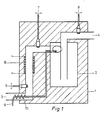
- a heat-insulated housing 1 contains a mixing chamber 2 inside, to which an inlet 3 and an outlet 4 are connected.
- an inlet temperature sensor 5 In the inlet 3, an inlet temperature sensor 5, a heater 6 as an electrical heating element and behind it an intermediate temperature sensor 7 and in the outlet 4 - that is, behind the mixing chamber 2 - an outlet temperature sensor 8 are arranged.
- a feed line 9 for a liquid anesthetic forms a heat exchanger 10 in the form of a pipe coil in the inlet 3 in front of the inlet temperature sensor 5. The feed line 9 then runs from there separately from the inlet 3 through the housing 1. It enters the inlet 3 behind the intermediate temperature sensor 7 and ends together with the latter in a tangential introduction into the mixing chamber 2.
- the breathing gas is fed in at the inlet 3 and then enters the mixing chamber 2 tangentially from there.
- the liquid anesthetic supplied through the feed line 9 evaporates and mixes uniformly with the breathing gas. Adjusted by the heat exchanger 10, the breathing gas and the liquid anesthetic have the same temperature behind the heat exchanger 10.
- the temperature is determined by the inlet temperature sensor 5.
- the heater 6 increases the temperature of the breathing gas before it enters the mixing chamber 2 to an intermediate temperature, to be represented later, which is measured by the intermediate temperature sensor 7.
- the outlet temperature sensor 8 measures the temperature of the anesthetic-respiratory gas mixture emerging from the mixing chamber 2 via the outlet 4.
- the heater 6 is operated in a controlled manner until the same temperature T 5 and T 8 , that is to say a temperature difference of zero, is established between the inlet temperature sensor 5 and the outlet temperature sensor 8 .
- T 5 and T 8 that is to say a temperature difference of zero
- the heating power supplied just covers the evaporation heat of the anesthetic stream M N supplied. External influences are eliminated by the thermal insulation of the housing 1.
- the measurement is independent of the respiratory gas flow Mg, since its amount, composition and temperature in the inlet and outlet 4 are the same.
- the heater 6 in operation heats the respiratory gas flow Mg flowing through the inlet 3.
- the temperature sensors 5, 7, 8 are resistance sensors. They are connected to the inputs of two amplifiers 12, 13 with associated matching resistors 11.
- the amplifier 12 feeds the heater 6 such that the temperatures of the inlet temperature sensor 5 and the outlet temperature sensor 8 become the same.
- Current meters 14 and voltmeters 15 arranged in the lines provide a display 17 of the anesthetic current M N via a power meter 16.
- the signal from the power meter 16 is simultaneously input to a computer 18.
- the amplifier 13 forms a signal from the heating of the breathing gas which occurs in the heater 6, determined between the inlet temperature sensor 5 and the intermediate temperature sensor 7, and sends this to the computer 18.
- the values for the respiratory gas flow Mg and with are generated from these signals the anesthetic flow M N, the concentration is determined and displayed on displays 20 and 21.
- this mixture and thus its specific heat c g must be known.
- the mixing ratio is determined (the components oxygen and nitrous oxide or oxygen and air are customary for anesthesia purposes) on the basis of the heat conduction.
- the heat transfer from the heater 6 into the breathing gas is dependent on this, and therefore a different temperature of the heater also belongs to a heating of the breathing gas detected at the intermediate temperature sensor 7.
- the data are added to the computer 18 in memories.
- a switch 23 is used to switch the memory when the components used are changed.
- a resistance meter 19 forms a signal which corresponds to the temperature-dependent resistance of the heater 6 and which is used in the computer 18 as a measure of the temperature of the heater 6. From the measured values and the stored data, the computer 18 then determines the existing mixing ratio, output with the Display 22 and the breathing gas flow, output with display 20.
Description
- Die Erfindung betrifft eine Vorrichtung zur Beimischung flüssiger Narkosemittel in das dem Patienten zuzuführende Atemgas mit einer Steuer- und Auswerteschaltung und Einrichtungen zur geregelten Zuführung des Atemgases sowie des Narkosemittels, mit einer Mischkammer in einem wärmeisolierten Gehäuse mit einem Einlaß für das Atemgas vor, sowie mit einem Auslaß für das Atemgas plus dem verdunsteten Narkosemittel hinter der Mischkammer, wobei der Einlaß einen Einlaßtemperaturfühler und der Auslaß einen Auslaßtemperaturfühler besitzen.
- In Geräten der Medizintechnik, bei denen irgendein Versagen zu lebensbedrohenden Umständen für den Patienten führen kann, ist es selbstverständlich, daß Bauteile oder deren Anordnungen von anderen unabhängig funktionierenden Bauteilen überwacht werden oder Verknüpfungen vorhanden sind, bei denen Differenzen zwischen Ist- und Sollwert Signale geben. Mit dem Signal werden visuelle oder auditive Signale ausgelöst und/oder automatische Abhilfemaßnahmen, wie z. B. das Umschalten auf Reservebaugruppen, eingeleitet.
- Eine in der älteren Anmeldung DE-AI-3116951 dargestellte Vorrichtung zur Beimischung flüssiger Narkosemittel in das dem Patienten zuzuführende Atemgas dient der Überwachung der Konzentration. des Atemgasdurchflusses und der flüssigen Narkosemittelmenge. Sie nutzt dazu die Erscheinung, daß bei der Verdunstung des dem Atemgas beigemischten flüssigen Narkosemittels eine Temperaturerniedrigung eintritt, die von dem Verhältnis zwischen der verdunsteten Narkosemittelmenge und der Atemgasmenge, also der Konzentration, abhängt. Über einen Einlaß wird das Atemgas zusammen mit dem über eine Zuführungsleitung zugeleiteten Narkosemittel von außen in eine wärmeisolierte Mischkammer eingeführt; sie mündet tangential in diese, um eine zyklonartige Strömung zu bilden. Vor der Mischkammer bildet die in dem Einlaß geführte Zuführungsleitung einen Wärmeaustauscher. Zwischen dem Wärmeaustauscher und der Mischkammer ragt ein Einlaßtemperaturfühler in den Einlaß. Ein Auslaß für das Gemisch aus dem Atemgas plus dem verdunsteten Narkosemittel führt aus der Mischkammer nach außen zum Patienten. Er enthält hinter der Mischkammer einen Auslaßtemperaturfühler. Die Wand der Mischkammer besitzt eine elektrische Heizung. Die beiden Meßfühler und die Heizung sind mit einer Steuer- und Auswerteschaltung verbunden, die periodisch zwischen zwei Betriebsphasen umschaltet. In der ersten Phase wird die Heizung derart geregelt betrieben, daß Temperaturgleichheit zwischen den beiden Temperaturfühlern besteht. Die zugeführte gemessene Heizleistung entspricht damit der Verdunstungswärme der zugeführten flüssigen Narkosemittelmenge und ist ein Maß für den Narkosemittelfluß. In der zweiten Phase ist die Heizung ausgeschaltet, und es wird bei voller Verdunstung die sich zwischen den beiden Temperaturfühlern einstellende Temperaturdifferenz festgestellt. Sie hängt von dem Verhältnis zwischen verdunsteter Narkosemittelmenge und Atemgasmenge ab, ist also ein Maß für die Konzentration des Narkosemittels im Atemgas. Der Quotient aus den Meßergebnissen beider Phasen bildet ein Maß für den Atemgasdurchfluß, es gilt dann

- Aufgabe der Erfindung ist eine Vorrichtung zur Beimischung flüssiger Narkosemittel in das dem Patienten zuzuführende Atemgas, die mit einfachem Aufbau kurzfristig in konstanter Arbeitsweise einen kontinuierlichen Angleich auch bei Extremforderungen in bezug auf Atemgasmengen und gewünschte Konzentration sichert und dabei die Forderung nach einer sicheren Überwachung durch das Personal und/oder einer automatischen Einleitung von Abhilfen erfüllt.
- Die Lösung der Aufgabe erfolgt gemäß dem Kennzeichen des Anspruchs 1. Das Kennzeichen des Anspruchs 2 bestimmt den Aufbau der Steuer- und Auswerteschaltung.
- Die Vorrichtung nach der Erfindung bietet die Möglichkeit der Kontrolle des Narkosemittelstromes. des Atemgasstromes und seines Mischverhältnisses sowie der Einhaltung der gewünschten Konzentration. Die Anordnung eines dritten Temperaturfühlers. nämlich des Zwischentemperaturfühlers, zwischen dem Einlaßtemperaturfühler und dem Auslaßtemperaturfühler noch im Einlaß hinter der hier angebrachten Heizung erlaubt, daß die Funktionen mit der Kontrolle des Narkosemittelstromes, des Atemgasstromes, des Mischverhältnisses und der Feststellung der Konzentration kontinuierlich ablaufen können. Die Heizung vor der Mischkammer im Einlaß garantiert die vollständige Verdunstung des flüssigen Narkosemittels.
- Dabei sind die Messung der Leistungsaufnahme und der Temperatur der Heizung durch die Feststellung der Spannung und des Stromes sowie die bekannten Temperaturen der drei Temperaturfühler zusammen mit den bekannten Daten des Narkosemittels und der Komponenten des Atemgases die Basis für die Feststellung der kontrollierten Werte.
- Weil die Messungen zeitlich gleichzeitig erfolgen, sind alle Meßwerte unter Berücksichtigung der thermischen Zeitkonstante der Vorrichtung jederzeit verfügbar. Es besteht mit den bekannten Änderungsgeschwindigkeiten die Möglichkeit einer Vorhersage.
- Eine Ausführung der Erfindung ist im folgenden beschrieben. Dabei zeigen
- Figur 1 die Mischvorrichtung,
- Figur 2 das Schaltschema der Steuer- und Auswerteschaltung.
- Ein wärmeisoliertes Gehäuse 1 enthält im Innern eine Mischkammer 2, an die ein Einlaß 3 und ein Auslaß 4 angeschlossen sind. Im Einlaß 3 sind ein Einlaßtemperaturfühler 5, eine Heizung 6 als elektrisches Heizelement sowie dahinter ein Zwischentemperaturfühler 7 und im Auslaß 4 - also hinter der Mischkammer 2 - ein Auslaßtemperaturfühler 8 angeordnet. Eine Zuführungsleitung 9 für ein flüssiges Narkosemittel bildet im Einlaß 3 vor dem Einlaßtemperaturfühler 5 einen Wärmeaustauscher 10 in Form einer Rohrschlange. Die Zuführungsleitung 9 verläuft dann von dort getrennt von dem Einlaß 3 durch das Gehäuse 1. Sie tritt hinter dem Zwischentemperaturfühler 7 wieder in den Einlaß 3 ein und endet mit diesem zusammen in tangentialer Einführung in der Mischkammer 2.
- Das Atemgas wird am Einlaß 3 zugeführt und tritt von dort aus dann tangential in die Mischkammer 2 ein. In der sich ausbildenden zyklonartigen Strömung verdunstet das durch die Zuführungsleitung 9 zugeführte flüssige Narkosemittel und mischt sich dabei gleichmäßig mit dem Atemgas. Durch den Wärmeaustauscher 10 angeglichen besitzen das Atemgas und das flüssige Narkosemittel hinter dem Wärmeaustauscher 10 die gleiche Temperatur. Die Temperatur wird durch den Einlaßtemperaturfühler 5 festgestellt. Durch die Heizung 6 wird die Temperatur des Atemgases vor dem Eintritt in die Mischkammer 2 auf eine später noch darzustellende Zwischentemperatur, die durch den Zwischentemperaturfühler 7 gemessen wird, erhöht. Der Auslaßtemperaturfühler 8 mißt die Temperatur des aus der Mischkammer 2 über den Auslaß 4 austretenden Narkosemittel-Atemgas-Gemisches.
- Das in Fig. 2 dargestellte Schaltbild der Steuer- und Auswerteschaltung steuert die oben beschriebene Vorrichtung gemäß folgenden Gedankengängen, wobei
- a) der Atemgasstrom Mg und
- b) der Narkosemittelstrom MN
- c) die Temperaturen T5 an dem Einlaßtemperaturfühler 5 und T8 an dem Auslaßtemperaturfühler 8 gleich sind, also T5 = T8,
- d) die Temperatur T7 am Zwischentemperaturfühler 7 gemessen wird,
- e) c9 die spezifische Wärme des bekannten Atemgases,
- f) qf die Verdunstungswärme des flüssigen Narkosemittels und
- g) Q6 die Leistungsaufnahme der Heizung sind.
- Zur Überwachung des Narkosemittelstromes MN wird die Heizung 6 geregelt betrieben, bis sich zwischen dem Einlaßtemperaturfühler 5 und dem Auslaßtemperaturfühler 8 die gleiche Temperatur T5 und T8, also eine Temperaturdifferenz Null einstellt. In diesem Zustand deckt die zugeführte Heizleistung gerade die Verdunstungswärme des zugeführten Narkosemittelstromes MN. Eine Beeinflussung von außen ist durch die Wärmeisolierung des Gehäuses 1 ausgeschaltet. Die Messung ist unabhängig vom Atemgasstrom Mg, da dessen Menge, Zusammensetzung und Temperatur im Einlaß und Auslaß 4 gleich sind.
- Die in Funktion befindliche Heizung 6 heizt den durch den Einlaß 3 fließenden Atemgasstrom Mg auf. Die sich mit T5 = T8 am Zwischentemperaturfühler 7 einstellende Temperatur T7 wird gemessen. Für die Vorrichtung gilt jetzt
-

- Die Temperaturfühler 5, 7, 8 sind Widerstandsfühler. Sie sind mit zugehörigen Abgleichwiderständen 11 mit den Eingängen zweier Verstärker 12, 13 verbunden.
- Der Verstärker 12 speist die Heizung 6 derart, daß die Temperaturen des Einlaßtemperaturfühlers 5 und des Auslaßtemperaturfühlers 8 gleich werden. In den Leitungen angeordnete Strommesser 14 und Spannungsmesser 15 ergeben über einen Leistungsmesser 16 eine Anzeige 17 des Narkosemittelstromes MN.
- Das Signal des Leistungsmessers 16 wird zugleich einem Rechner 18 eingegeben. Der Verstärker 13 bildet ein Signal aus der in der Heizung 6 eintretenden Erwärmung des Atemgases, festgestellt zwischen dem Einlaßtemperaturfühler 5 und dem Zwischentemperaturfühler 7, und gibt dieses an den Rechner 18. Im Rechner 18 werden aus diesen Signalen die Werte für den Atemgasstrom Mg und mit dem Narkosemittelstrom MN die Konzentration ermittelt und auf Anzeigen 20 und 21 angezeigt.
- Werden als Atemgas verschiedene Gasgemische benutzt, dann muß dieses Gemisch und damit seine spezifische Wärme cg bekannt sein. Die Bestimmung des Mischverhältnisses erfolgt bei bekannten Komponenten (für Narkosezwecke sind die Komponenten Sauerstoff und Lachgas oder Sauerstoff und Luft üblich) aufgrund der Wärmeleitung. Von dieser ist der Wärmeübergang von der Heizung 6 in das Atemgas abhängig, gehört also auch eine andere Temperatur der Heizung zu einer am Zwischentemperaturfühler 7 festgestellten Erwärmung des Atemgases. Die Daten sind dem Rechner 18 in Speichern beigegeben. Ein Umschalter 23 dient der Speicherumschaltung bei einem Wechsel der benutzten Komponenten. Aus den Signalen des Strommessers 14 und des Spannungsmessers 15 bildet ein Widerstandsmesser 19 ein Signal, das dem temperaturabhängigen Widerstand der Heizung 6 entspricht und im Rechner 18 als Maß für die Temperatur der Heizung 6 dient. Aus den gemessenen Werten und den Speicherdaten bestimmt der Rechner 18 dann das vorhandene Mischverhältnis, ausgegeben mit der Anzeige 22 und den Atemgasstrom, ausgegeben mit der Anzeige 20.
vorgegeben sind,
Claims (2)
Applications Claiming Priority (2)
| Application Number | Priority Date | Filing Date | Title |
|---|---|---|---|
| DE3234474A DE3234474C2 (de) | 1982-09-17 | 1982-09-17 | Vorrichtung zur Beimischung flüssiger Narkosemittel in das dem Patienten zuzuführende Atemgas |
| DE3234474 | 1982-09-17 |
Publications (2)
| Publication Number | Publication Date |
|---|---|
| EP0106015A1 EP0106015A1 (de) | 1984-04-25 |
| EP0106015B1 true EP0106015B1 (de) | 1986-12-03 |
Family
ID=6173456
Family Applications (1)
| Application Number | Title | Priority Date | Filing Date |
|---|---|---|---|
| EP83105800A Expired EP0106015B1 (de) | 1982-09-17 | 1983-06-14 | Vorrichtung zur Beimischung flüssiger Narkosemittel in das dem Patienten zuzuführende Atemgas |
Country Status (5)
| Country | Link |
|---|---|
| US (1) | US4587966A (de) |
| EP (1) | EP0106015B1 (de) |
| JP (1) | JPS5964064A (de) |
| DE (1) | DE3234474C2 (de) |
| ES (1) | ES8404192A1 (de) |
Families Citing this family (29)
| Publication number | Priority date | Publication date | Assignee | Title |
|---|---|---|---|---|
| DE3401923A1 (de) * | 1984-01-20 | 1985-08-01 | Drägerwerk AG, 2400 Lübeck | Vorrichtung zur beimischung fluessiger narkosemittel in das dem patienten zuzufuehrende atemgas |
| SE449565C (sv) * | 1984-06-28 | 1990-01-04 | Gambro Engstrom Ab | Narkos- och/eller respiratoranlaeggning innefattande en befuktnings- och/eller foergasningskammare |
| US4879997A (en) * | 1988-04-07 | 1989-11-14 | Bickford Allan M | Anesthetic vaporizer |
| CH676203A5 (de) * | 1988-09-27 | 1990-12-28 | Draegerwerk Ag | |
| US4881541A (en) * | 1988-12-21 | 1989-11-21 | The Regents Of The University Of California | Vaporizer for an anesthetic having a vapor pressure about one atmosphere |
| GB9000042D0 (en) * | 1990-01-03 | 1990-03-07 | Ralph John F | Decorative wall covering applied to steel radiators |
| FI89210C (fi) * | 1990-06-08 | 1993-08-25 | Instrumentarium Oy | Foerfarande foer identifiering av gaser |
| EP0469797B2 (de) * | 1990-08-02 | 2001-12-12 | Datex-Ohmeda Inc. | Narkosemittelverdampfer |
| DE4105164C2 (de) * | 1991-02-20 | 1999-06-02 | Draegerwerk Ag | Arretierung für eine Dosiervorrichtung eines Narkosemittelverdunsters |
| DE4105858C2 (de) * | 1991-02-25 | 1999-07-15 | Draegerwerk Ag | Narkosemittelverdunster für niedrigsiedende Narkosemittelflüssigkeiten |
| DE4107060C2 (de) * | 1991-03-06 | 1999-07-01 | Draegerwerk Ag | Dosiervorrichtung für ein flüssiges Narkosemittel über einen Zwischenbehälter |
| US5226411A (en) * | 1991-03-07 | 1993-07-13 | Walter Levine | Aerosol nebulizer heater |
| DE4111965C2 (de) * | 1991-04-12 | 2000-03-23 | Draegerwerk Ag | Verfahren zur Kalibrierung eines Strömungssensors in einem Atemsystem |
| DE4116512A1 (de) * | 1991-05-21 | 1992-11-26 | Draegerwerk Ag | Narkosemittelverdunster mit durchstroembaren verdunsterelementen |
| FI92468C (fi) * | 1991-11-15 | 1994-11-25 | Instrumentarium Oy | Laitteisto anestesia-aineen annostelemiseksi potilaalle |
| US5335650A (en) * | 1992-10-13 | 1994-08-09 | Temple University - Of The Commonwealth System Of Higher Education | Process control for liquid ventilation and related procedures |
| US5509405A (en) * | 1994-11-21 | 1996-04-23 | Ohmeda Inc. | Pump flow vaporizer |
| US6694975B2 (en) | 1996-11-21 | 2004-02-24 | Aradigm Corporation | Temperature controlling device for aerosol drug delivery |
| US6131570A (en) | 1998-06-30 | 2000-10-17 | Aradigm Corporation | Temperature controlling device for aerosol drug delivery |
| JP3827814B2 (ja) * | 1997-06-11 | 2006-09-27 | 三菱電機株式会社 | 筒内噴射式燃料制御装置 |
| DE19829018B4 (de) * | 1998-06-30 | 2005-01-05 | Markus Lendl | Verfahren zur Einstellung einer in seiner Dosisrate gezielt veränderlichen Dosiervorrichtung für ein Narkosemittel und Narkosesystem dazu |
| DE10105434C1 (de) * | 2001-02-07 | 2002-04-25 | Draeger Medical Ag | Vorrichtung und Verfahren zur Überwachung der Zuführung flüssiger Anästhesiemittel |
| US8393321B2 (en) * | 2001-10-17 | 2013-03-12 | Piramal Critical Care, Inc. | Drug delivery system for conscious sedation |
| DE102006027052B3 (de) * | 2006-06-10 | 2007-08-09 | Dräger Medical AG & Co. KG | Verfahren zur Messung des Anästhesiemittelverbrauchs in einem Beatmungssystem |
| US8267081B2 (en) | 2009-02-20 | 2012-09-18 | Baxter International Inc. | Inhaled anesthetic agent therapy and delivery system |
| US8920732B2 (en) | 2011-02-15 | 2014-12-30 | Dcns | Systems and methods for actively controlling steam-to-carbon ratio in hydrogen-producing fuel processing systems |
| DE102014008625A1 (de) | 2014-06-17 | 2015-12-17 | Drägerwerk AG & Co. KGaA | Vorrichtung und Verfahren zur Dosierung eines Narkosemittels in einen Gasstrom |
| EP3484566B1 (de) | 2016-07-14 | 2020-02-12 | Drägerwerk AG & Co. KGaA | Dosiervorrichtung zum einbringen eines anästhesiemittels in einen atemgasstrom |
| US11199491B2 (en) * | 2018-09-07 | 2021-12-14 | Board Of Regents, The University Of Texas System | Photothermal absorbance measurement in a flow system |
Family Cites Families (7)
| Publication number | Priority date | Publication date | Assignee | Title |
|---|---|---|---|---|
| AT195028B (de) * | 1956-12-03 | 1958-01-25 | Erna Ledwina | Klardampfinhalator |
| DE1271902B (de) * | 1966-07-21 | 1968-07-04 | Draegerwerk Heinr & Berh Draeg | Vorrichtung zur Beimischung fluessiger Narkosemittel in das dem Patienten zuzufuehrende Atemgas |
| DE1922404B2 (de) * | 1969-05-02 | 1974-04-25 | Draegerwerk Ag, 2400 Luebeck | Narkosemittel verdunster |
| DE2158701A1 (de) * | 1971-11-26 | 1973-05-30 | Original Hanau Quarzlampen | Regelvorrichtung fuer narkosemittelverdunster |
| DE2702674C3 (de) * | 1977-01-24 | 1981-02-12 | Draegerwerk Ag, 2400 Luebeck | Atemgasbefeuchter |
| IL52690A (en) * | 1977-08-09 | 1982-03-31 | Yeda Res & Dev | Apparatus for controlled heating of the nasal passages |
| DE3116951C2 (de) * | 1981-04-29 | 1984-12-20 | Drägerwerk AG, 2400 Lübeck | Vorrichtung zur Beimischung flüssiger Narkosemittel in das dem Patienten zuzuführende Atemgas |
-
1982
- 1982-09-17 DE DE3234474A patent/DE3234474C2/de not_active Expired
-
1983
- 1983-06-14 EP EP83105800A patent/EP0106015B1/de not_active Expired
- 1983-08-10 ES ES524853A patent/ES8404192A1/es not_active Expired
- 1983-09-08 JP JP58164256A patent/JPS5964064A/ja active Granted
- 1983-09-13 US US06/531,689 patent/US4587966A/en not_active Expired - Fee Related
Also Published As
| Publication number | Publication date |
|---|---|
| JPS5964064A (ja) | 1984-04-11 |
| ES524853A0 (es) | 1984-05-01 |
| DE3234474C2 (de) | 1984-11-29 |
| US4587966A (en) | 1986-05-13 |
| JPS6365B2 (de) | 1988-01-05 |
| DE3234474A1 (de) | 1984-03-22 |
| EP0106015A1 (de) | 1984-04-25 |
| ES8404192A1 (es) | 1984-05-01 |
Similar Documents
| Publication | Publication Date | Title |
|---|---|---|
| EP0106015B1 (de) | Vorrichtung zur Beimischung flüssiger Narkosemittel in das dem Patienten zuzuführende Atemgas | |
| DE3116951C2 (de) | Vorrichtung zur Beimischung flüssiger Narkosemittel in das dem Patienten zuzuführende Atemgas | |
| EP0065271B1 (de) | Verfahren zum Mischen von Gasen in einem vorgegebenen Verhältnis und zum Dosieren der Gasmischung | |
| DE2451383C3 (de) | Regler für ein Insufflationsgerät | |
| DE2654248C2 (de) | Anordnung zur Bestimmung der Alkoholkonzentration des Bluts | |
| EP0778941B1 (de) | Messeinrichtung und verfahren zur bestimmung des wassergehaltes in einem gas | |
| WO1989003201A1 (en) | Therapeutic appliance for effecting cooling | |
| CH619781A5 (de) | ||
| EP1017997B1 (de) | Verfahren und vorrichtung zur bestimmung der enthalpie von nassdampf | |
| DE10297601B4 (de) | Vorrichtung und Verfahren zur Wärmeableitung in einem thermischen Massenstrom-Sensor | |
| DE2213760C2 (de) | Vorrichtung zum Messen von in Warmwasser-Heizungsanlagen verbrauchten Wärmemengen | |
| DE3346563A1 (de) | Verfahren und vorrichtung zur ueberwachung und steuerung eines verdampfers | |
| DE2750450C3 (de) | Beatmungsgerät | |
| DE3732475A1 (de) | Beatmungsgeraet | |
| DE10105434C1 (de) | Vorrichtung und Verfahren zur Überwachung der Zuführung flüssiger Anästhesiemittel | |
| DE2119128A1 (de) | Gas-Chromatografsystem sowie mit diesem verwendbarer Strömungsprogrammierer | |
| DE2407940A1 (de) | Vorrichtung zur messung von kohlenwasserstoff | |
| DE102005000964B3 (de) | Vorrichtung und Verfahren zur Messung einer Volumenstromdifferenz | |
| EP3851150A1 (de) | Anästhesiemitteldosiervorrichtung mit einer messeinheit | |
| DE19960437A1 (de) | Vorrichtung und Verfahren zur Messung der Strömungsgeschwindigkeit eines Gases | |
| DE2505669A1 (de) | Verfahren und gasanalysator zur bestimmung der zusammensetzung und stroemungsgeschwindigkeit von gasen | |
| CH442793A (de) | Einrichtung zum Messen der Wärmeleitfähigkeit und des Wärmeflusses | |
| DE2847217A1 (de) | Anordnung zur messung der waermeenergieabgabe von raumheizkoerpern | |
| AT392544B (de) | Analysengeraet zur messung fluessiger oder gasfoermiger proben | |
| DE3340793C1 (de) | Verfahren zum Messen der Wärmeaufnahme oder -abgabe eines Mediums über ein Objekt, insbesondere zur Wärmemessung bei Heizsystemen |
Legal Events
| Date | Code | Title | Description |
|---|---|---|---|
| PUAI | Public reference made under article 153(3) epc to a published international application that has entered the european phase |
Free format text: ORIGINAL CODE: 0009012 |
|
| AK | Designated contracting states |
Designated state(s): CH FR GB IT LI NL SE |
|
| 17P | Request for examination filed |
Effective date: 19840523 |
|
| ITF | It: translation for a ep patent filed |
Owner name: UFFICIO TECNICO ING. A. MANNUCCI |
|
| GRAA | (expected) grant |
Free format text: ORIGINAL CODE: 0009210 |
|
| AK | Designated contracting states |
Kind code of ref document: B1 Designated state(s): CH FR GB IT LI NL SE |
|
| ET | Fr: translation filed | ||
| PGFP | Annual fee paid to national office [announced via postgrant information from national office to epo] |
Ref country code: NL Payment date: 19870630 Year of fee payment: 5 |
|
| PLBE | No opposition filed within time limit |
Free format text: ORIGINAL CODE: 0009261 |
|
| STAA | Information on the status of an ep patent application or granted ep patent |
Free format text: STATUS: NO OPPOSITION FILED WITHIN TIME LIMIT |
|
| 26N | No opposition filed | ||
| PG25 | Lapsed in a contracting state [announced via postgrant information from national office to epo] |
Ref country code: LI Effective date: 19880630 Ref country code: CH Effective date: 19880630 |
|
| PG25 | Lapsed in a contracting state [announced via postgrant information from national office to epo] |
Ref country code: NL Effective date: 19890101 |
|
| NLV4 | Nl: lapsed or anulled due to non-payment of the annual fee | ||
| PG25 | Lapsed in a contracting state [announced via postgrant information from national office to epo] |
Ref country code: FR Free format text: LAPSE BECAUSE OF NON-PAYMENT OF DUE FEES Effective date: 19890228 |
|
| REG | Reference to a national code |
Ref country code: CH Ref legal event code: PL |
|
| REG | Reference to a national code |
Ref country code: FR Ref legal event code: ST |
|
| PGFP | Annual fee paid to national office [announced via postgrant information from national office to epo] |
Ref country code: GB Payment date: 19920526 Year of fee payment: 10 |
|
| PGFP | Annual fee paid to national office [announced via postgrant information from national office to epo] |
Ref country code: SE Payment date: 19920615 Year of fee payment: 10 |
|
| PG25 | Lapsed in a contracting state [announced via postgrant information from national office to epo] |
Ref country code: GB Effective date: 19930614 |
|
| PG25 | Lapsed in a contracting state [announced via postgrant information from national office to epo] |
Ref country code: SE Effective date: 19930615 |
|
| GBPC | Gb: european patent ceased through non-payment of renewal fee |
Effective date: 19930614 |
|
| EUG | Se: european patent has lapsed |
Ref document number: 83105800.3 Effective date: 19940110 |