EP0105022A2 - Baukasten zum Zusammenstellen von Lasthebe- und/oder Verzurranordnungen - Google Patents
Baukasten zum Zusammenstellen von Lasthebe- und/oder Verzurranordnungen Download PDFInfo
- Publication number
- EP0105022A2 EP0105022A2 EP83730089A EP83730089A EP0105022A2 EP 0105022 A2 EP0105022 A2 EP 0105022A2 EP 83730089 A EP83730089 A EP 83730089A EP 83730089 A EP83730089 A EP 83730089A EP 0105022 A2 EP0105022 A2 EP 0105022A2
- Authority
- EP
- European Patent Office
- Prior art keywords
- kit according
- load capacity
- coupling member
- coupling members
- components
- Prior art date
- Legal status (The legal status is an assumption and is not a legal conclusion. Google has not performed a legal analysis and makes no representation as to the accuracy of the status listed.)
- Granted
Links
- 230000008878 coupling Effects 0.000 claims abstract description 78
- 238000010168 coupling process Methods 0.000 claims abstract description 78
- 238000005859 coupling reaction Methods 0.000 claims abstract description 78
- 210000003128 head Anatomy 0.000 claims description 23
- 238000003780 insertion Methods 0.000 claims description 15
- 230000037431 insertion Effects 0.000 claims description 15
- 238000010276 construction Methods 0.000 claims description 11
- 210000000078 claw Anatomy 0.000 claims description 4
- 239000000463 material Substances 0.000 claims description 4
- 238000004904 shortening Methods 0.000 claims description 4
- 239000000725 suspension Substances 0.000 description 4
- 238000001125 extrusion Methods 0.000 description 1
- 210000000056 organ Anatomy 0.000 description 1
Images


Classifications
-
- B—PERFORMING OPERATIONS; TRANSPORTING
- B66—HOISTING; LIFTING; HAULING
- B66C—CRANES; LOAD-ENGAGING ELEMENTS OR DEVICES FOR CRANES, CAPSTANS, WINCHES, OR TACKLES
- B66C1/00—Load-engaging elements or devices attached to lifting or lowering gear of cranes or adapted for connection therewith for transmitting lifting forces to articles or groups of articles
- B66C1/10—Load-engaging elements or devices attached to lifting or lowering gear of cranes or adapted for connection therewith for transmitting lifting forces to articles or groups of articles by mechanical means
- B66C1/12—Slings comprising chains, wires, ropes, or bands; Nets
- B66C1/18—Band-type slings
-
- B—PERFORMING OPERATIONS; TRANSPORTING
- B66—HOISTING; LIFTING; HAULING
- B66C—CRANES; LOAD-ENGAGING ELEMENTS OR DEVICES FOR CRANES, CAPSTANS, WINCHES, OR TACKLES
- B66C1/00—Load-engaging elements or devices attached to lifting or lowering gear of cranes or adapted for connection therewith for transmitting lifting forces to articles or groups of articles
- B66C1/10—Load-engaging elements or devices attached to lifting or lowering gear of cranes or adapted for connection therewith for transmitting lifting forces to articles or groups of articles by mechanical means
- B66C1/12—Slings comprising chains, wires, ropes, or bands; Nets
- B66C1/14—Slings with hooks
Definitions
- the invention relates to a kit, in particular for assembling load lifting and / or lashing arrangements, on the one hand consisting of belts of different load capacities and on the other hand consisting of components that can be connected to them by coupling members, such as hooks, eyes, shackles, fork heads; Shortening claws, connection adapters or the like. as well as tensioning and / or control devices also of different load capacities.
- coupling members such as hooks, eyes, shackles, fork heads; Shortening claws, connection adapters or the like.
- tensioning and / or control devices also of different load capacities.
- Modules of the above type are known, the components of which can be combined by the respective user according to his needs.
- the known construction kits there is a considerable risk that, for example, components and belts of different load-bearing capacities will be connected to one another when putting together a load lifting arrangement. Such a wrong combination can have extremely unpleasant consequences if it contains an undersized component that breaks under load.
- the invention has for its object to provide a kit of the type under consideration, in which the risk of incorrect combinations is kept as small as possible.
- This object is achieved in that the coupling members are designed as assignment elements for the belts and the components or belts or tensioning and / or control devices of the same load capacity.
- the construction kit according to the invention offers the advantage which increases the safety of the user to a decisive degree, that his user e.g. a load lifting arrangement only has to select a coupling member that corresponds to the expected load and then with this coupling member, which fulfills the function of a gauge, can couple the parts that match the load capacity.
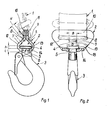
- 1 is a belt to which a component 3 formed by a hook is connected via a coupling member 2.
- the component 3 has a substantially plate-shaped head 4 with a diameter D and a height h.
- the head 4 is followed by a cylindrical neck 5 with a diameter d, the length of which is equal to 1.
- the upper end 6 of the component 3 is flattened on two opposite sides such that the distance between the flats is substantially equal to the diameter d.
- the flats facilitate the insertion of the neck 5 in a longitudinal slot 7 of the coupling member 2, which opens into a transverse slot 8 at an angle of 90 0th
- the width B of the longitudinal slot 7 is only a little larger than the diameter d of the neck 5 of a component suitable for the coupling member, but smaller than the diameter D of the corresponding head 4.
- the diameter D of the head 4 of smaller components can be smaller than the width B of the longitudinal slot 7 of the coupling member shown, so that components 3 with a smaller load-bearing capacity cannot be held in the coupling member shown.
- the latter has viewed in the direction of insertion of the head 4 (cf. FIG. 1) a clear height H which is greater than the height h of the head 4.
- the coupling member 2 is also provided with a provided second transverse slot 9, but in which no longitudinal slot opens.
- the transverse slots 8 and 9 are delimited at the top by two cross members 10 and 11, which extend from the ends of the side walls 12 and 13 of the dome ment member 2 are formed.
- the side walls 12 and 13 are partially oblique to one another. They pass into a base 14, the width of which, as can be seen in FIG. 2, is smaller than the greatest width of the side walls 12 and 13.
- the thickness s of the side walls 12 and 13 and of the base 14 is smaller than the length 1 of the Neck 5 of component 3 of a certain combination, but greater than the length of the neck of components of lower load-bearing capacity. Consequently, these cannot be inserted at all into the coupling element shown.
- the belt 1 fulfills a double function, namely on the one hand the function of a load-bearing member and on the other hand the function of a securing element.
- the width of the transverse slot 8 serves as a selection criterion for the belt to be connected in each case.
- a belt of smaller dimensions ie a smaller load-bearing capacity
- the transverse slot 8 ie there is no inevitable confusion between the coupling member 2 and the belt 1.
- a such inevitable confusion is given in the embodiment of Figures 3 and 4.
- the parts which correspond to the parts in FIG. 1 and FIG. 2 are provided with the same reference symbols. For the sake of simplicity, only the differences between the constructions are discussed below.
- 15 is a belt loop which forms the end of a belt 1. The clear height A of this belt loop 15 is fixed.
- the belt loop 15 is held by an abutment 16 in a coupling member 17, which serves to connect the belt loop 15 to the component 3.
- the coupling member 17 also has a longitudinal slot 7. However, this does not open into transverse slots, as in the case described first, but into an insertion opening 18 which is delimited by lateral yokes 19 and 20. In order to be able to insert the abutment 16 into the coupling member 17, this is open on both sides.
- the belt loop 15 and the abutment 16 assume the position indicated by dash-dotted lines in FIG. From this position, the belt loop 15, viewed in FIGS. 3 and 4, is pulled upwards until the abutment 16 can be locked in the supporting position by a securing element 21 designed as a tensioning pin, in which the supporting pins 22 and 23 are in the yokes 19 and 20 support.
- the abutment 16 is provided with an assignment tongue 24.
- This assignment tongue 24 is matched to the clear height A of the belt loop 15, which in turn is determined as a function of the load capacity of the belt 1.
- the coupling members and belts are subdivided into different load capacity levels such that, for example, the assignment tongue of abutments of coupling elements of higher load capacity can no longer be inserted into the belt loop of a belt.
- the width of the belts is graded in such a way that belts of higher load capacity levels do not fit into the insertion openings of coupling members of lower load capacity.
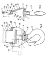
- FIGS. 5 and 6 show a belt 1 detachably connected to a cross member 25 of a coupling member 26.
- the coupling member 26 is formed by a housing, the sides of which form insertion openings 27 and 28.
- the bottom 29 of the coupling member 26 there is an insertion opening 30 for an adapter 31 with a conical head 32.
- the height of the head 32 is so great that the adapter 31 when the belt is inserted into the transverse slots 33 and 34 automatically is locked in the coupling member 26.
- an adapter 31 offers the advantage that, for example, components of chain building blocks can be used for belt building blocks.
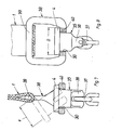
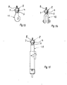
- FIGS. 7 and 8 show an adapter 35 with a connecting fork 36 into which a chain link 37 is suspended.
- the coupling member 38 which is also connected to a belt 1 here, is formed by a frame, one longitudinal leg 39 of which forms a cross member for the belt 1 and the other longitudinal leg 40 has a bearing for the adapter 35.
- the dimensions H and D are also coordinated with one another in this case so that when the belt 1 is fitted, it is not possible to remove the adapter 35 from the coupling member 38.
- FIGS. 9 and 10 largely corresponds in terms of its basic structure to the arrangement according to FIGS. 3 and 4.
- a belt loop 15 is connected by an abutment 41 to a coupling member 42, into which a component designed as an adapter is provided with a connecting eye 43 is mounted.
- the component 43 like the abutment 41, is inserted into the coupling member 42 from the side.
- the abutment 41 here has an assignment tongue 44, which is made of a different material than the rest of the abutment 41, which forms the support pins 22 and 23.
- the material for the assignment tongue 44 is particularly rubber or a rubber-elastic plastic.
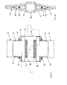
- FIGS. 11 and 12 show an arrangement for connecting two belt loops 15 with the aid of two abutments 16 and a coupling member 46.
- the coupling member 46 has two insertion openings 10.
- FIGS. 13 to 18 show that, for example, with the particularly advantageous coupling member 2 components and devices of various types can be coupled.
- a component 47 designed as a shortening claw is coupled to a coupling member 2.
- a component 48 designed as a shackle is used, and in FIG. 15, a tensioning and control device 49 is suspended in the coupling member 2.
- a belt 1 is suspended via a coupling member 2, into which a component 50 designed as an adapter is suspended link 51 connected.
- two straps 1 are connected to a suspension link 51 via two intermediate links 52, two components 50 and two coupling links 2. 53 are hangers with information about the load-bearing capacity of the suspension links.
- the coupling members are of crucial importance in the construction kits described, since they assume the assignment of components and belts.
- the coupling elements according to FIGS. 1 to 6 can be produced in a simple manner by stamping or extrusion as a mass article.
Landscapes
- Engineering & Computer Science (AREA)
- Mechanical Engineering (AREA)
- Hooks, Suction Cups, And Attachment By Adhesive Means (AREA)
- Buckles (AREA)
Abstract
Description
- Die Erfindung betrifft einen Baukasten, insbesondere zum Zusammenstellen von Lasthebe- und/oder Verzurranordnungen, einerseits bestehend aus Gurten unterschiedlicher Tragfähigkeit und andererseits bestehend aus mit diesen durch Kupplungsglieder verbindbaren Bauteilen, wie Haken, Ösen, Schäkeln, Gabelköpfen; Verkürzungsklauen, Anschlußadaptern od.dgl. sowie Spann- und/oder Kontrollvorrichtungen ebenfalls unterschiedlicher Tragfähigkeit.
- Bekannt sind Baukästen der vorstehenden Art, deren Bestandteile vom jeweiligen Anwender seinen Bedürfnissen entsprechend miteinander kombiniert werden können. Beim Einsatz der bekannten Baukästen besteht eine erhebliche Gefahr, daß beispielsweise beim Zusammenstellen einer Lasthebeanordnung Bauteile und Gurte unterschiedlicher Tragfähigkeit miteinander verbunden werden. Eine derartige Fehlkombination kann äußerst unangenehme Folgen nach sich ziehen, wenn sie ein unterdimensioniertes Bauteil beinhaltet, das. unter Last zu Bruch geht.
- Die vorstehend angedeutete Problematik der Fehlkombination von Teilen eines Baukastens ist als solche nicht unbekannt. Sie hat auf dem Gebiet der Kettengeschirre zur Entwicklung von Baukästen aus Rundgliederketten und mit diesen kuppelbaren Organen geführt, bei denen die Gefahr, daß eine Kette bestimmter Tragkraft mit einem Bauteil zu kleiner Tragkraft gekuppelt wird, mehr oder weniger eliminiert ist.
- Bei den bekannten Baukästen für Rundgliederketten sind die Ketten bzw. deren Glieder maßlich direkt auf die jeweiligen Bauteile abgestimmt. Eine entsprechende Lösung wäre grundsätzlich auch bei Gurtbaukästen denkbar, ist jedoch bis heute nicht bekannt geworden.
- Der Erfindung liegt die Aufgabe zugrunde, einen Baukasten der in Betracht gezogenen Art zu schaffen, bei dem die Gefahr von Fehlkombinationen möglichst klein gehalten ist. Diese Aufgabe wird erfindungsgemäß dadurch gelöst, daß die Kupplungsglieder als Zuordnungselemente für die Gurte und die Bauteile bzw. Gurte bzw. Spann- und/oder Kontrollvorrichtungen gleicher Tragfähigkeit ausgebildet sind.
- Der erfindungsgemässe Baukasten bietet den die Sicherheit des Anwenders in entscheidendem Maße erhöhenden Vorteil, daß sein Anwender beim Zusammenstellen z.B. einer Lasthebeanordnung lediglich ein der zu erwartenden Last entsprechendes Kupplungsglied auszuwählen hat und anschliessend mit diesem Kupplungsglied, das die Funktion einer Lehre erfüllt, die tragfähigkeitsmässig zusammenpassenden Teile kuppeln kann.
- Die Erfindung wird im folgenden anhand der beigefügten Zeichnung näher erläutert. Es zeigen:
- Figur 1 teilweise im Schnitt die Seitenansicht eines von einem Haken gebildeten durch ein Kupplungsglied mit einem Gurt verbundenen Bauteiles,
- Figur 2 teilweise im Schnitt die Vorderansicht der in Figur 1 dargestellten Teile,
- Figur 3 teilweise im Schnitt die Seitenansicht eines von einem Haken gebildeten durch ein Kupplungsglied mit der Schlaufe eines Gurtes verbundenen Bauteiles,
- Figur 4 teilweise im Schnitt die Vorderan- - sicht der in Figur 3 dargestellten Teile,
- Figur 5 teilweise im Schnitt die Seitenansicht eines von einem Adapter gebildeten durch ein Kupplungsglied mit einem Gurt verbundenen Bauteiles,
- Figur 6 teilweise im Schnitt die Vorderansicht der in Figur 5 dargestellten Teile,
- Figur 7 teilweise im Schnitt die Seitenansicht eines weiteren von einem Adapter gebildeten durch ein Kupplungsglied mit einem Gurt verbundenen Bauteiles,
- Figur 8 teilweise im Schnitt die Vorderansicht der in Figur 7 dargestellten Teile,
- Figur 9 teilweise im Schnitt die Seitenansicht eines von einem Anschlußadapter gebildeten durch ein Kupplungsglied mit der Schlaufe eines Gurtes verbundenen Bauteiles,
- Figur 10 teilweise im Schnitt die Vorderansicht der in Figur 9 dargestellten Teile,
- Figur 11 teilweise im Schnitt die Seitenansicht zweier durch ein Kupplungsglied verbundener Gurte,
- Figur 12 die Seitenansicht der in Figur 11 dargestellten Teile,
- Figur 13 teilweise im Schnitt die Seitenansicht eines Kupplungsgliedes mit einer eingehängten Verkürzungsklaue,
- Figur 14 teilweise im Schnitt die Seitenansicht eines Kupplungsgliedes mit einem eingehängten Schäkel,
- Figur 15 teilweise im Schnitt die Seitenansicht eines Kupplungsgliedes mit einer eingehängten Spann- und Kontrollvorrichtung,
- Figur 16 teilweise im Schnitt die Vorderansicht eines durch ein Kupplungsglied mit einem Gurt verbundenen in die Öse eines Adapters eingeschweißten Aufhängegliedes,
- Figur 17 teilweise im Schnitt die Seitenansicht der Teile gemäß Figur 16 und
- Figur 18 die Vorderansicht eines über Zwischenglieder und Kupplungsglieder mit zwei Gurten verbundenen Bauteiles.
- In den Figuren 1 und 2 ist 1 ein Gurt, mit dem über ein Kupplungsglied 2 ein von einem Haken gebildetes Bauteil 3 verbunden ist.
- Das Bauteil 3 besitzt einen im wesentlichen tellerförmigen Kopf 4 mit einem Durchmesser D und einer Höhe h. An den Kopf 4 schließt sich ein zylindrischer Hals 5 mit einem Durchmesser d an, dessen Länge gleich 1 ist. Das obere Ende 6 des Bauteiles 3 ist an zwei sich gegenüberliegenden Seiten derart abgeflacht, daß der Abstand zwischen den Abflachungen im wesentlichen gleich dem Durchmesser d ist. Die Abflachungen erleichtern das Einführen des Halses 5 in einen Längsschlitz 7 des Kupplungsgliedes 2, der unter einem Winkel von 900 in einen Querschlitz 8 mündet. Die Breite B des Längsschlitzes 7 ist nur'wenig grösser als der Durchmesser d des Halses 5 eines zum Kupplungsglied tragfähigkeitsmässig passenden Bauteiles, aber kleiner als der Durchmesser D des entsprechenden Kopfes 4. Der Durchmesser D des Kopfes 4 kleinerer Bauteile kann kleiner sein als die Breite B des Längsschlitzes 7 des dargestellten Kupplungsgliedes, so daß Bauteile 3 kleinerer Tragfähigkeit im dargestellten Kupplungsglied keinen Halt finden. Um das Einführen des Kopfes in den gurtfreien Querschlitz 8 zu ermöglichen, hat dieser in Einführrichtung des Kopfes 4 betrachtet (vgl. Figur 1) eine lichte Höhe H, die grösser ist als die Höhe h des Kopfes 4. Das Kupplungsglied 2 ist außerdem mit einem zweiten Querschlitz 9 versehen, in den jedoch kein Längsschlitz mündet. Die Querschlitze 8 und 9 werden oben durch zwei Querträger 10 und 11 begrenzt, welche von den Enden der Seitenwände 12 und 13 des Kupplungsgliedes 2 gebildet werden. Die Seitenwände 12 und 13 verlaufen teilweise schräg zueinander. Sie gehen in einen Boden 14 über, dessen Breite, wie der Figur 2 entnommen werden kann, kleiner ist als die größte Breite der Seitenwände 12 und 13. Die Stärke s der Seitenwände 12 und 13 sowie des Bodens 14 ist kleiner als die Länge 1 des Halses 5 des Bauteiles 3 einer bestimmten Komb in ation, jedoch grösser als die Länge des Halses von Bauteilen kleinerer Tragfähigkeit. Diese können folglich in das dargestellte Kupplungsglied überhaupt nicht eingeführt werden.
- Mit Rücksicht darauf, daß die lichte Höhe H des Querschlitzes 8 nur wenig größer als die Höhe h des Kopfes 4 ist, wird das Bauteil 3 bei in die Querschlitze 8 und 9 eingeführtem Gurt durch letzteren im Kupplungsglied 2 verriegelt. Der Gurt 1 erfüllt mit anderen Worten eine doppelte Funktion, nämlich einmal die Funktion eines Lastaufnahmeorgans und zum anderen die Funktion eines Sicherungselementes.
- Bei dem in den Figuren 1 und 2 dargestellten Ausführungsbeispiel dient die Breite des Querschlitzes 8 als Auswahlkriterium für den jeweils anzuschliessenden Gurt. Es ist jedoch möglich, in den Querschlitz 8 einen Gurt kleinerer Abmessungen, d.h. kleiner Tragfähigkeit, einzuführen, d.h. eine zwangsläufige Verwechslungsfreiheit zwischen dem Kupplungsglied 2 und dem Gurt 1 fehlt. Eine solche zwangsläufige Verwechslungsfreiheit ist bei dem Ausführungsbeispiel gemäß den Figuren 3 und 4 gegeben. In diesen Figuren sind die Teile, die den Teilen der Figur 1 und der Figur 2 entsprechen, mit den gleichen Bezugszeichen versehen. Im folgenden wird der Einfachheit halber lediglich auf die Unterschiede zwischen den Konstruktionen eingegangen. 15 ist eine Gurtschlaufe, die das Ende eines Gurtes 1 bildet. Die lichte Höhe A dieser Gurtschlaufe 15 liegt fest. Die Gurtschlaufe 15 wird durch ein Widerlager 16 in einem Kupplungsglied 17 gehalten, das dazu dient, die Gurtschlaufe 15 mit dem Bauteil 3 zu verbinden.
- Auch das Kupplungsglied 17 besitzt einen Längsschlitz 7. Dieser mündet jedoch nicht wie im zuerst beschriebenen Fall in Querschlitze sondern in eine Einführöffnung18, die durch seitliche Joche 19 und 20 begrenzt ist. Um das Widerlager 16 in das Kupplungsglied 17 einführen zu können, ist dieses an beiden Seiten offen. Beim Einführen des Widerlagers 16 nehmen die Gurtschlaufe 15 und das Widerlager 16 die in Figur 3 durch strichpunktierte Linien angedeutete Lage ein. Aus dieser Lage wird die Gurtschlaufe 15 in den Figuren 3 und 4 betrachtet nach oben gezogen, bis das Widerlager 16 durch ein als Spannstift ausgebildetes Sicherungselement 21 in der Stützstellung arretiert werden kann, in der sich die Stützzapfen 22 und 23 in den Jochen 19 und 20 abstützen.
- Um eine verwechslungsfreie Zuordnung von Gurten bzw. Gurtschlaufen und Kupplungsgliedern gleicher Tragfähigkeit sicherzustellen, ist das Widerlager 16 mit einer Zuordnungszunge 24 versehen. Diese Zuordnungszunge 24 ist auf die lichte Höhe A der Gurtschlaufe 15 abgestimmt, die ihrerseits in Abhängigkeit von der Tragfähigkeit des Gurtes 1 festgelegt ist. In der Praxis erfolgt eine Unterteilung der Kupplungsglieder und Gurte in verschiedene Tragfähigkeitsstufen dergestalt, daß beispielsweise in die Gurtschlaufe eines Gurtes einer bestimmten Tragfähigkeit die Zuordnungszunge von Widerlagern von Kupplungsgliedern höherer Tragfähigkeit nicht mehr einführbar ist. Gleichzeitig ist auch die Breite der Gurte dergestalt gestuft, daß Gurte höherer Tragfähigkeitsstufen nicht in Einführöffnungen von Kupplungsgliedern kleinerer Tragfähigkeit passen.
- Die verwechslungsfreie Zuordnung zwischen dem Kupplungsglied 17 und dem Bauteil 3 erfolgt in der gleichen Weise wie im Falle der Figuren 1 und 2.
- Die Figuren 5 und 6 zeigen einen lösbar mit einem Querträger 25 eines Kupplungsgliedes 26 verbundenen Gurt 1. Das Kupplungsglied 26 wird in diesem Fall von einem Gehäuse gebildet, dessen Seiten Einführöffnungen 27 und 28 formen. Im Boden 29 des Kupplungsgliedes 26 befindet sich eine Einstecköffnung 30 für einen Adapter 31 mit einem kegelförmigen Kopf 32. Wie aus Figur 6 entnehmbar ist, ist die Höhe des Kopfes 32 so groß, daß bei in die Querschlitze 33 und 34 eingeführtem Gurt der Adapter 31 automatisch im Kupplungsglied 26 verriegelt ist.
- Die Verwendung eines Adapters 31 bietet den Vorteil, daß beispielsweise Bauteile von Kettenbaukästen für Gurtbaukästen verwendbar sind.
- Während bei dem Ausführungsbeispiel gemäß Figuren 5 und 6 ein Adapter 31 mit einer Anschlußöse Verwendung findet, zeigen die Figuren 7 und 8 einen Adapter 35 mit einer Anschlußgabel 36, in die ein Kettenglied 37 eingehängt ist. Das auch hier mit einem Gurt 1 verbundene Kupplungsglied 38 wird von einem Rahmen gebildet, dessen einer Längsschenkel 39 einen Querträger für den Gurt 1 formt und dessen anderer Längsschenkel 40 ein Lager für den Adapter 35 aufweist. Die Maße H und D sind auch in diesem Fall so aufeinander abgestimmt, daß bei montiertem Gurt 1 ein Entfernen des Adapters 35 aus dem Kupplungsglied 38 nicht möglich ist.
- Die Anordnung gemäß den Figuren 9 und 10 entspricht hinsichtlich ihres prinzipiellen Aufbaues weitgehend der Anordnung gemäss den Figuren 3 und 4. Auch hier ist eine Gurtschlaufe 15 durch ein Widerlager 41 mit einem Kupplungsglied 42 verbunden, in das ein mit einer Anschlußöse versehenes als Adapter ausgebildetes Bauteil 43 eingehängt ist. In diesem Falle wird das Bauteil 43 wie das Widerlager 41 von der Seite in das Kupplungsglied 42 eingeführt. Die Unterschiede zwischen der in den Figuren 3 und 4 beschriebenen und dieser Anordnung bestehen darin, daß das Widerlager 41 hier eine Zuordnungszunge 44 aufweist, die aus einem anderen Material besteht als der die Stützzapfen 22 und 23 bildende Rest des Widerlagers 41. Als Material für die Zuordnungszunge 44 eignen sich insbesondere Gummi oder ein gummielastischer Kunststoff. Aufgrund der begrenzten Materialfestigkeit einer solchen Zuordnungszunge ist eine andere Sicherung des Widerlagers 41 als bei der zuerst beschriebenen Anordnung erforderlich. Sie besteht darin, daß Sicherungselemente 45 außerhalb der Stützzapfen 22 und 23 in die Schenkel der Joche 19 und 20 eingeführt werden.
- In den Figuren 11 und 12 ist eine Anordnung zum Verbinden zweier Gurtschlaufen 15 mit Hilfe zweier Widerlager 16 und eines Kupplungsgliedes 46 dargestellt. Das Kupplungsglied 46 besitzt in diesem Fall zwei Einführöffnungen 10.
- Die Figuren 13 bis 18 zeigen, daß man beispielsweise mit dem besonders vorteilhaften Kupplungsglied 2 Bauteile und Vorrichtungen unterschiedlichster Art kuppeln kann. In Figur 13 ist mit einem Kupplungsglied 2 ein als Verkürzungsklaue ausgebildetes Bauteil 47 gekuppelt. In Figur 14 findet ein als Schäkel ausgebildetes Bauteil 48 Verwendung, und in Figur 15 ist in das Kupplungsglied 2 eine Spann- und Kontrollvorrichtung 49 eingehängt. Bei der Anordnung gemäß Figuren 15 und 16 ist ein Gurt 1 über ein Kupplungsglied 2, in das ein als Adapter ausgebildetes Bauteil 50 eingehängt ist, mit einem Aufhängeglied 51 verbunden. In Figur 18 stehen mit einem Aufhängeglied 51 über zwei Zwischenglieder 52, zwei Bauteile 50 und zwei Kupplungsglieder 2 zwei Gurte 1 in Verbindung. 53 sind Aufhänger mit Informationen über die Tragfähigkeit der Aufhängeglieder.Bei allen in den Figuren 13 bis 18 dargestellten Anordnungen wird erreicht, daß der jeweilige Anwender zwangsläufig die richtige Zahl von Gurten 1 an das jeweilige Aufhängeglied 51 anschließt.
- Die vorstehenden Ausführungen machen deutlich, daß den Kupplungsgliedern bei den beschriebenen Baukästen entscheidende Bedeutung zukommt, da sie die Zuordnung von Bauteilen und Gurten übernehmen. Insbesondere die Kupplungsglieder gemäß den Figuren 1 bis 6 lassen sich in einfacher Weise durch Stanzen oder Strangpressen als Massenartikel herstellen.
Claims (29)
Priority Applications (1)
| Application Number | Priority Date | Filing Date | Title |
|---|---|---|---|
| AT83730089T ATE39981T1 (de) | 1982-09-21 | 1983-09-21 | Baukasten zum zusammenstellen von lasthebeund/oder verzurranordnungen. |
Applications Claiming Priority (4)
| Application Number | Priority Date | Filing Date | Title |
|---|---|---|---|
| DE3235301A DE3235301C2 (de) | 1982-09-21 | 1982-09-21 | Anordnung zum Verbinden von mit Gurtschlaufen versehenen Enden von Gurten |
| DE3235301 | 1982-09-21 | ||
| DE3235302 | 1982-09-21 | ||
| DE3235302A DE3235302C2 (de) | 1982-09-21 | 1982-09-21 | Baukasten zum Zusammenstellen von Lasthebe- und/oder Verzurranordnungen |
Publications (3)
| Publication Number | Publication Date |
|---|---|
| EP0105022A2 true EP0105022A2 (de) | 1984-04-04 |
| EP0105022A3 EP0105022A3 (en) | 1985-01-09 |
| EP0105022B1 EP0105022B1 (de) | 1989-01-11 |
Family
ID=25804672
Family Applications (1)
| Application Number | Title | Priority Date | Filing Date |
|---|---|---|---|
| EP83730089A Expired EP0105022B1 (de) | 1982-09-21 | 1983-09-21 | Baukasten zum Zusammenstellen von Lasthebe- und/oder Verzurranordnungen |
Country Status (1)
| Country | Link |
|---|---|
| EP (1) | EP0105022B1 (de) |
Cited By (3)
| Publication number | Priority date | Publication date | Assignee | Title |
|---|---|---|---|---|
| WO2007040430A1 (en) * | 2005-10-06 | 2007-04-12 | Frenolink Förvaltnings AB | Lifting sling system |
| WO2022099734A1 (zh) * | 2020-11-12 | 2022-05-19 | 昆山凯禄电子科技有限公司 | 一种具有卡接结构的起重环形吊带 |
| EP4046953A1 (de) | 2021-02-17 | 2022-08-24 | Jörg Sembritzky | Modulares system zur aufhängung an einem kranhaken oder einem anschlagpunkt oder einem zurrpunkt, sowie koppelhaken zur anwendung in einer solchen anordnung |
Families Citing this family (2)
| Publication number | Priority date | Publication date | Assignee | Title |
|---|---|---|---|---|
| DE19652193A1 (de) * | 1996-12-16 | 1998-06-18 | Werner Sobek Ingenieure Gmbh | Gelenkiger Zuggliedenbeschlag mit bandförmigen Laschen |
| CN111204652B (zh) * | 2020-02-02 | 2021-02-23 | 饶建明 | 一种钢丝绳分股均衡受力装置 |
Family Cites Families (4)
| Publication number | Priority date | Publication date | Assignee | Title |
|---|---|---|---|---|
| GB166684A (en) * | 1920-04-19 | 1921-07-19 | Joseph Sidney Pratten | Shackle |
| US3656797A (en) * | 1970-04-02 | 1972-04-18 | Ralph A Ratcliff | Hoist housing-hook combination |
| DE2335131B2 (de) * | 1973-07-06 | 1976-06-10 | Rud-Kettenfabrik Rieger & Dietz, 7080 Aalen | Baukasten aus rundgliederketten und mit diesen kuppelbaren organen |
| DE2806996C3 (de) * | 1978-02-18 | 1981-03-12 | Fa. August Thiele, 5860 Iserlohn | Flexibles Hebeband |
-
1983
- 1983-09-21 EP EP83730089A patent/EP0105022B1/de not_active Expired
Cited By (5)
| Publication number | Priority date | Publication date | Assignee | Title |
|---|---|---|---|---|
| WO2007040430A1 (en) * | 2005-10-06 | 2007-04-12 | Frenolink Förvaltnings AB | Lifting sling system |
| CN101277893B (zh) * | 2005-10-06 | 2011-04-20 | 弗雷诺林克·福瓦尔廷斯股份公司 | 提升吊重系统和用于提升吊重系统中的信息载体 |
| US8157304B2 (en) | 2005-10-06 | 2012-04-17 | Frenolink Förvaltnings AB | Lifting sling system |
| WO2022099734A1 (zh) * | 2020-11-12 | 2022-05-19 | 昆山凯禄电子科技有限公司 | 一种具有卡接结构的起重环形吊带 |
| EP4046953A1 (de) | 2021-02-17 | 2022-08-24 | Jörg Sembritzky | Modulares system zur aufhängung an einem kranhaken oder einem anschlagpunkt oder einem zurrpunkt, sowie koppelhaken zur anwendung in einer solchen anordnung |
Also Published As
| Publication number | Publication date |
|---|---|
| EP0105022B1 (de) | 1989-01-11 |
| EP0105022A3 (en) | 1985-01-09 |
Similar Documents
| Publication | Publication Date | Title |
|---|---|---|
| DE2745649A1 (de) | Anschlagmittel-aufnahmekopf fuer anschlaggeschirre mit rohrfoermigen distanztraversen | |
| DE2819986C2 (de) | Hebe- und Transportgeschirr mit Ausgleichswippe, insbesondere zur Verwendung mit Ketten-Anschlaggeschirren und mit Hebebandanordnungen | |
| DE2208509C3 (de) | Verbindungsglied für Ketten, insbesondere Reifenketten | |
| DE29623539U1 (de) | Hebeverbindungsvorrichtung | |
| EP0105022A2 (de) | Baukasten zum Zusammenstellen von Lasthebe- und/oder Verzurranordnungen | |
| DE4026157A1 (de) | Befestigungsvorrichtung | |
| DE3235302C2 (de) | Baukasten zum Zusammenstellen von Lasthebe- und/oder Verzurranordnungen | |
| DE3235299C2 (de) | Anordnung zum Verbinden von Bauteilen sowie von Spann- und/oder Kontrollvorrichtungen von Hebe- und/oder Verzurranordnungen mit Gurten | |
| DE2233615C3 (de) | Kettenschloß | |
| DE3502946C2 (de) | Kettenförderer | |
| DE3149237C2 (de) | Gleitschutzkette für Fahrzeugräder | |
| AT391006B (de) | Verbindungsstueck fuer kettengehaenge | |
| EP1300360A1 (de) | Lasthaken mit Verkürzungsklaue | |
| DE1916996B2 (de) | Zug- und Drückevorrichtung für Kraftfahrzeuge, insbesondere für Schlepper | |
| DE2262975C3 (de) | Kontrollorgan zur Überlastkontrolle von Ketten | |
| DE3235301C2 (de) | Anordnung zum Verbinden von mit Gurtschlaufen versehenen Enden von Gurten | |
| EP0104135A2 (de) | Anordnung zum Verbinden von Bauteilen sowie Spann- und/oder Kontrollvorrichtung von Hebe- und/oder Verzurranordnungen mit Gurten | |
| DE2744736A1 (de) | Kettenverbinder und einkuerzungsglied, insbesondere fuer rundstahlketten | |
| DE3136844C2 (de) | ||
| DE3235300C2 (de) | Anordnung zum Verbinden von Bauteilen sowie von Spann- und/oder Kontrollvorrichtungen von Hebe- oder Verzurranordnungen mit Gurten | |
| DE2809176C2 (de) | Einschienenhängebahnschiene für den Untertagebetrieb | |
| DE3048565C2 (de) | Gabelkopfelement | |
| AT257384B (de) | Gleitschutzkette | |
| EP0574798B1 (de) | Kette, wie Rücke-, Choker- oder Anschlagkette | |
| DE3828523C2 (de) |
Legal Events
| Date | Code | Title | Description |
|---|---|---|---|
| PUAI | Public reference made under article 153(3) epc to a published international application that has entered the european phase |
Free format text: ORIGINAL CODE: 0009012 |
|
| AK | Designated contracting states |
Designated state(s): AT CH GB LI NL SE |
|
| PUAL | Search report despatched |
Free format text: ORIGINAL CODE: 0009013 |
|
| AK | Designated contracting states |
Designated state(s): AT CH GB LI NL SE |
|
| 17P | Request for examination filed |
Effective date: 19850620 |
|
| GRAA | (expected) grant |
Free format text: ORIGINAL CODE: 0009210 |
|
| AK | Designated contracting states |
Kind code of ref document: B1 Designated state(s): AT CH GB LI NL SE |
|
| REF | Corresponds to: |
Ref document number: 39981 Country of ref document: AT Date of ref document: 19890115 Kind code of ref document: T |
|
| GBT | Gb: translation of ep patent filed (gb section 77(6)(a)/1977) | ||
| PLBE | No opposition filed within time limit |
Free format text: ORIGINAL CODE: 0009261 |
|
| STAA | Information on the status of an ep patent application or granted ep patent |
Free format text: STATUS: NO OPPOSITION FILED WITHIN TIME LIMIT |
|
| 26N | No opposition filed | ||
| PGFP | Annual fee paid to national office [announced via postgrant information from national office to epo] |
Ref country code: AT Payment date: 19920924 Year of fee payment: 10 |
|
| PGFP | Annual fee paid to national office [announced via postgrant information from national office to epo] |
Ref country code: NL Payment date: 19920930 Year of fee payment: 10 |
|
| PGFP | Annual fee paid to national office [announced via postgrant information from national office to epo] |
Ref country code: CH Payment date: 19921019 Year of fee payment: 10 |
|
| PG25 | Lapsed in a contracting state [announced via postgrant information from national office to epo] |
Ref country code: AT Effective date: 19930921 |
|
| PG25 | Lapsed in a contracting state [announced via postgrant information from national office to epo] |
Ref country code: LI Effective date: 19930930 Ref country code: CH Effective date: 19930930 |
|
| PG25 | Lapsed in a contracting state [announced via postgrant information from national office to epo] |
Ref country code: NL Effective date: 19940401 |
|
| NLV4 | Nl: lapsed or anulled due to non-payment of the annual fee | ||
| REG | Reference to a national code |
Ref country code: CH Ref legal event code: PL |
|
| EAL | Se: european patent in force in sweden |
Ref document number: 83730089.6 |
|
| PGFP | Annual fee paid to national office [announced via postgrant information from national office to epo] |
Ref country code: GB Payment date: 19970902 Year of fee payment: 15 |
|
| PGFP | Annual fee paid to national office [announced via postgrant information from national office to epo] |
Ref country code: SE Payment date: 19970919 Year of fee payment: 15 |
|
| PG25 | Lapsed in a contracting state [announced via postgrant information from national office to epo] |
Ref country code: GB Free format text: LAPSE BECAUSE OF NON-PAYMENT OF DUE FEES Effective date: 19980921 |
|
| PG25 | Lapsed in a contracting state [announced via postgrant information from national office to epo] |
Ref country code: SE Free format text: LAPSE BECAUSE OF NON-PAYMENT OF DUE FEES Effective date: 19980922 |
|
| GBPC | Gb: european patent ceased through non-payment of renewal fee |
Effective date: 19980921 |
|
| EUG | Se: european patent has lapsed |
Ref document number: 83730089.6 |