EP0103421A2 - Transportregelung für Glasscheibenverarbeitungsanlage - Google Patents
Transportregelung für Glasscheibenverarbeitungsanlage Download PDFInfo
- Publication number
- EP0103421A2 EP0103421A2 EP83304731A EP83304731A EP0103421A2 EP 0103421 A2 EP0103421 A2 EP 0103421A2 EP 83304731 A EP83304731 A EP 83304731A EP 83304731 A EP83304731 A EP 83304731A EP 0103421 A2 EP0103421 A2 EP 0103421A2
- Authority
- EP
- European Patent Office
- Prior art keywords
- glass
- sheets
- conveyor
- conveyance
- auxiliary
- Prior art date
- Legal status (The legal status is an assumption and is not a legal conclusion. Google has not performed a legal analysis and makes no representation as to the accuracy of the status listed.)
- Granted
Links
- 239000011521 glass Substances 0.000 title claims abstract description 190
- 238000012545 processing Methods 0.000 title claims description 29
- 238000006073 displacement reaction Methods 0.000 claims abstract description 20
- 238000005452 bending Methods 0.000 claims description 58
- 238000011144 upstream manufacturing Methods 0.000 claims description 7
- 238000010438 heat treatment Methods 0.000 description 15
- 230000007246 mechanism Effects 0.000 description 10
- 230000007423 decrease Effects 0.000 description 7
- 238000002360 preparation method Methods 0.000 description 4
- 239000007787 solid Substances 0.000 description 4
- 229910000831 Steel Inorganic materials 0.000 description 3
- 230000015654 memory Effects 0.000 description 3
- 238000012544 monitoring process Methods 0.000 description 3
- 239000010959 steel Substances 0.000 description 3
- 230000001133 acceleration Effects 0.000 description 2
- 230000009471 action Effects 0.000 description 2
- 238000004891 communication Methods 0.000 description 2
- 238000001514 detection method Methods 0.000 description 2
- 230000006870 function Effects 0.000 description 2
- 238000012423 maintenance Methods 0.000 description 2
- 238000004519 manufacturing process Methods 0.000 description 2
- 238000000034 method Methods 0.000 description 2
- 230000008569 process Effects 0.000 description 2
- 238000010791 quenching Methods 0.000 description 2
- 238000003860 storage Methods 0.000 description 2
- 238000005496 tempering Methods 0.000 description 2
- 238000012546 transfer Methods 0.000 description 2
- 230000004075 alteration Effects 0.000 description 1
- 230000008859 change Effects 0.000 description 1
- 238000010276 construction Methods 0.000 description 1
- 238000001816 cooling Methods 0.000 description 1
- 230000003247 decreasing effect Effects 0.000 description 1
- 238000010586 diagram Methods 0.000 description 1
- 230000005484 gravity Effects 0.000 description 1
- 239000000463 material Substances 0.000 description 1
- 230000003763 resistance to breakage Effects 0.000 description 1
Images


Classifications
-
- B—PERFORMING OPERATIONS; TRANSPORTING
- B65—CONVEYING; PACKING; STORING; HANDLING THIN OR FILAMENTARY MATERIAL
- B65G—TRANSPORT OR STORAGE DEVICES, e.g. CONVEYORS FOR LOADING OR TIPPING, SHOP CONVEYOR SYSTEMS OR PNEUMATIC TUBE CONVEYORS
- B65G43/00—Control devices, e.g. for safety, warning or fault-correcting
- B65G43/10—Sequence control of conveyors operating in combination
-
- C—CHEMISTRY; METALLURGY
- C03—GLASS; MINERAL OR SLAG WOOL
- C03B—MANUFACTURE, SHAPING, OR SUPPLEMENTARY PROCESSES
- C03B35/00—Transporting of glass products during their manufacture, e.g. hot glass lenses, prisms
- C03B35/14—Transporting hot glass sheets or ribbons, e.g. by heat-resistant conveyor belts or bands
- C03B35/16—Transporting hot glass sheets or ribbons, e.g. by heat-resistant conveyor belts or bands by roller conveyors
- C03B35/163—Drive means, clutches, gearing or drive speed control means
- C03B35/164—Drive means, clutches, gearing or drive speed control means electric or electronicsystems therefor, e.g. for automatic control
-
- C—CHEMISTRY; METALLURGY
- C03—GLASS; MINERAL OR SLAG WOOL
- C03B—MANUFACTURE, SHAPING, OR SUPPLEMENTARY PROCESSES
- C03B2225/00—Transporting hot glass sheets during their manufacture
- C03B2225/02—Means for positioning, aligning or orientating the sheets during their travel, e.g. stops
-
- Y—GENERAL TAGGING OF NEW TECHNOLOGICAL DEVELOPMENTS; GENERAL TAGGING OF CROSS-SECTIONAL TECHNOLOGIES SPANNING OVER SEVERAL SECTIONS OF THE IPC; TECHNICAL SUBJECTS COVERED BY FORMER USPC CROSS-REFERENCE ART COLLECTIONS [XRACs] AND DIGESTS
- Y10—TECHNICAL SUBJECTS COVERED BY FORMER USPC
- Y10S—TECHNICAL SUBJECTS COVERED BY FORMER USPC CROSS-REFERENCE ART COLLECTIONS [XRACs] AND DIGESTS
- Y10S65/00—Glass manufacturing
- Y10S65/13—Computer control
Definitions
- This invention relates generally to controllers for conveyor positioning drives and, more particularly to controllers for conveyor variable speed drives used in glass sheet processing systems.
- Prior glass sheet processing systems such as, for example, the ones disclosed by U.S.Patents 3,778,244 4, 2 02,681, 4,204,854 and 4,282,026 include bending apparatus having a holder positioned within a heating chamber above a roller conveyor to receive a heated glass sheet from the conveyor in preparation for bending.
- High quality glass can be achieved with this type of system if the conveyance is continued as the glass sheet is received by.the holder from the conveyor since the glass sheet is then never stationary on the rollers in a manner that can result in roller marking of the lower glass surface.
- continued conveyance of the glass sheet as it is received by the holder necessarily results in sliding between the upper surface of the glass sheet and a downwardly facing surface of the holder.
- the surface material of the holder at which the sliding takes place must be capable of withstanding the sliding action and the heat involved without marking the upper surface of the glass sheet in its softened state. After the holder receives the heated glass sheet, a mold is moved under the holder and receives the heated glass sheet for bending. In certain applications, subsequent rapid cooling of the bent glass sheet provides tempering thereof to increase the glass strength and resistance to breakage.
- a pair of symmetrical right and left glass sheets are simultaneously bent such as in the manufacturing of right and left windows for vehicles.
- a pair of sheets are bent on the type of system discussed above, it is conventional for one sheet to be conveyed forward of the other sheet in leading and trailing positions as the sheets are heated from room temperature to a sufficiently high temperature for bending. After the glass sheets have been conveyed for a sufficient distance to be heated to the re- planetaryd temperature, the longitudinal spacing therebetween along the direction of conveyance can change from the initial position due to slippage between the conveyor rollers and the glass sheets.
- the molds which receive the glass sheets from the holder are positioned in a fixed relationship with respect to each other, it is important for the glass sheets to be uniformly spaced with respect to each other and at the same location on the holder during each cycle in order to perform bending of both sheets to the desired shape.
- Repositioning of the glass sheets with respect to each other can be accomplished by holding one sheet as the conveyance of the other continues. However, such repositioning results in slippage between the sheet that is held and the rolls of the conveyor and can produce scratches on the lower roll supported glass surfaces.
- One object of the present invention is to provide a controller for a variable speed drive that drives an auxiliary conveyor which is located adjacent a main conveyor in a glass sheet bending system so that sliding of a glass sheet is reduced upon being moved between the auxiliary conveyor and the main conveyor as the conveyance of the other glass sheets on the main conveyor is continued.
- Another object of the present invention is to provide a controller for a variable speed drive that drives an auxiliary conveyor which is located adjacent a main conveyor in a glass sheet bending system so, if needed, the leading and trailing glass sheets can be repositioned with respect to each other without any slippage between the sheets and the conveyors.
- a further object of the present invention is to provide a controller for a variable speed drive that drives an auxiliary conveyor which is located adjacent a main conveyor in a glass sheet bending system so that the auxiliary conveyor is controllably driven at a speed substantially equal to the speed of the main conveyor during transfer of the glass sheet between the main conveyor and the auxiliary conveyor in order to prevent marking of the glass.
- the glass sheet bending system includes main and auxiliary horizontal conveyors for con-- veying glass sheets.
- a drive mechanism drives the main conveyor to convey heated glass sheets supported thereby.
- Bending apparatus of the system receives heated glass sheets to perform the bending.
- a separate operator of the system operates the auxiliary conveyor to control movement thereof and glass sheet conveyance thereon independent of the glass sheet conveyance on the main conveyor.
- the operator comprises a variable speed drive for driving the auxiliary conveyor independently of the main conveyor to provide control of glass sheet conveyance.
- the controller controls the positioning drive to provide a controlled rate of conveyance to reduce sliding of the glass sheet.
- variable speed drive is controlled by the controller to increase or decrease the rate of conveyance on the auxiliary conveyor to reposition the glass sheets when needed.
- two speed changes of the variable.speed drive are sequentially performed to initially reposition the glass sheets with respect to each other and to thereafter reduce the rate of conveyance adjacent the bending apparatus to decrease the sliding that takes place as the glass sheets are received thereby from the auxiliary conveyor.
- variable speed drive is also controlled by the controller to drive the auxiliary conveyor at the same rate that the main conveyor is driven at the time glass sheet transfer occurs between the main and auxiliary conveyors and, preferably, at all times that the glass-sheets are not being removed or repositioned.
- variable speed drive includes a first continuous drive loop that drives the rolls of the auxiliary conveyor and the drive mechanism includes a second continuous drive loop for driving the rolls of the main conveyor.
- a pair of the first continuous drive loops and a pair of the second continuous drive loops are most preferably provided to drive their respective rolls, and a horizontal support surface is associated with each drive loop with each drive loop slidably supported thereby and the associated rolls supported thereon for frictional driving.
- Both pairs of drive loops preferably comprise chains, and the positioning drive loops are most preferably roller chains that are driven by an electric motor under the control of the controller of the present invention.
- the glass sheet bending system includes a furnace defining a heating chamber through which glass sheets are conveyed for heating in preparation for the bending.
- the bending apparatus of the preferred system includes a holder received within the heating chamber above the auxiliary conveyor for receiving heated glass sheets therefrom and also includes a bending mold or a pair of such molds for receiving the glass sheets from the holder for the bending.
- a control system monitors and controls the processing of a conveyed sheet of glass in the sheet bending system which operates at relatively high production rates.
- the control system insures that the glass sheet bending system bends glass sheets without damage to either the glass sheets or the bending system.
- the control system preferably includes sensor means located along the path of conveyance for sensing the pieces of glass as the pieces of glass are conveyed by the main conveyor.
- the sensor means provides a glass sense signal upon sensing each piece of glass.
- a first generating means is coupled to the main conveyor for generating a first transport signal corresponding to the distance that the glass sheets are conveyed along the path of conveyance.
- a master controller processes the glass sense and transport signals corresponding to each glass sheet to provide a command signal.
- a positioning controller for controlling the variable speed drive.
- the positioning controller includes the first generating means and a second generating means coupled to the auxiliary conveyor for generating a second transport signal corresponding to the distance that glass sheets are conveyed along the path of conveyance on the auxiliary conveyor.
- a slave controller processes the command signal and the first and second transport signals to provide at least one control signal to control glass sheet conveyance on the auxiliary conveyor independent of the glass sheet conveyance on the main conveyor.
- a preferred embodiment of the sensor means includes a source located on one side of the glass path for emitting radiant energy transverse the path of glass conveyance and a receiver located on the opposite side of the glass path for receiving the emitted radiant energy.
- the positioning controller provides a control signal to the variable speed drive to enable it to adjust the position of one piece of a plurality of pieces of glass relative to another piece of the plurality of pieces of glass if necessary.
- the sensor means preferably is located at a predetermined position along the longitudinal length of the heating chamber downstream from a positioning station for sensing the pieces of glass as-the pieces of glass are conveyed.
- the master controller is responsive to the glass sense signal of the sensor means to provide the command signal to the slave controller which preferably comprises a slave computer which, in turn, emits a digital control signal which is converted into an analog signal and provided to the variable speed drive so that the glass sheets are picked up without damaging either the glass sheets or the bending apparatus at the bending station.
- the master controller is a programmable computer which can accept various set points from an interconnected operator console unit corresponding to various physical parameters of the glass bending system.
- control system affords great flexibility in this application; the position of a photoelectric sensor pair can be changed along the longitudinal length of the conveyor and the set points utilized by the control system can be altered so that no alteration of the hardware is required.
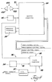
- a glass sheet bending system indicated generally by reference numeral 10 includes a schematically indicated furnace 12 having a heating chamber 14 within which glass sheets are heated and bent.
- a horizontal roller conveyor system includes a main roller conveyor 16 and an auxiliary roller conveyor 17. Both conveyors 16 and 17 include rolls 18 that support glass sheets during conveyance through the heating chamber 14 and which have elongated shapes extending horizontally transverse to the direction of conveyance in a parallel relationship to each other. Each conveyor roll 18 has a central rotational axis.
- a drive mechanism 20 of the system drives the rolls of the main conveyor 16 about their rotational axes to provide conveyance of glass sheets supported on the rolls for heating within the furnace heating chamber 14.
- a separate, variable speed drive 21 drives the rolls 18 of the auxiliary conveyor 17 adjacent bending apparatus 22 of the system in order to control movement thereof and glass sheet conveyance thereon independent of glass sheet conveyance on the rolls 18 of the main conveyor 16. It is also to be understood that many of the teachings of the present invention can also be applied to control the drive of an auxiliary conveyor located at a loading station, if required.
- bending apparatus 22 of the system receives the heated glass sheet to perform bending thereof in a manner which is hereinafter described.
- the furnace 12 of the system includes a housing of the type disclosed by United States Patents 3,934,970, 3,947,242 and 3,994,711 wherein a fixed lower housing 28 that opens upwardly and a vertically movable upper housing 3'0 that opens downwardly.cooperatively define the heating chamber 14 in a lower closed position of the upper housing.
- An upper open position of the upper housing 30 provides access to the heating chamber for removal of glass when necessary as well as for maintenance of the conveyor system.
- insulated lower and upper side walls 32 and 34 at each lateral side of the furnace define side slots 36 through which opposite ends of the . conveyor rolls 18 project for rotational driving thereof by the drive mechanism 20 and the variable speed drive 21 to provide glass sheet conveyance.
- the drive mechanism 20 for the main conveyor 16 preferably is of the frictional drive type disclosed by United States Patents 3,806,312, 3,934,970, 3,947,242, 3,994,711 and 4,133,667.
- a pair of continuous drive loops 38 of the drive mechanism are embodied by solid steel belts or toothed chains and respectively drive the roll ends that project outwardly from the furnace heating chamber through the adjacent side slots 36.
- Each drive loop 38 is received by an associated pair of sheaves 40 and includes an upper driving reach that is slidally supported on a horizontal support member (not shown) that extends the length of the conveyor outside of the heating chamber and alongside the adjacent side slot 36.
- the external location of the driving reach with respect to the heating chamber provides a lower use temperature and thereby minimizes maintenance as well as permitting the drive loop to be embodied by a chain that includes toothed links connected by pins.
- Such chain type drive loops permit the sheaves 40 to have teeth that establish a positive driving relationship with the sheaves as opposed to friction developed by the wrap tension as is the case with solid steel belts, and the chains also permit the sheaves to have a much smaller diameter than can be utilized with solid steel belts ' due to the smaller radius of curvature the chains can assume.
- each drive loop 38 is rotatively driven in a clockwise direction as shown by arrows 42 of FIGURE 1 so as to pull the upper driving reach toward the right and thereby also rotates the left sheave 40 in a clockwise direction.
- Longitudinal positioners (not shown) locate the opposite ends of the rolls 18 with respect to the support member along the direction of conveyance while permitting rotation of the rolls. Each roll end is supported on and frictionally driven by the driving reach of the adjacent drive loop 38 so as to provide the glass sheet conveyance.
- the bending apparatus 22 shown in FIGURE 1 is of the type disclosed by United States Patents 4,202,681, 4,204,854, 4,222,763, and 4,282,026 wherein a vertically movable holder 44 has a downwardly facing surface 46 with restricted openings spaced over the extent thereof and connected to a vacuum drawing unit 48 that draws a vacuum within the openings.
- the holder 44 is alternately and selectively raised or lowered by a holder lift unit 45 as shown by FIGURE 3 which is of the type shown in the U.S. Patent 4,282,026. Downward movement of the holder 44 into proximity with a heated glass sheet G conveyed thereunder and drawing of the vacuum lifts the heated glass sheet so as to be secured to the downwardly facing holder surface 46.
- variable speed drive 21 includes at least one and preferably two continuous drive loops 54 (only one of which is shown in FIGURE 3 for simplicity) which is preferably embodied by a roller chain that drives rolls J8 of the auxiliary conveyor 17 adjacent the bending apparatus 22.
- the drive mechanism 20 includes a second continuous drive loop 38 for driving the rolls 18 of the main conveyor 16 upstream and downstream from the bending apparatus 22 (only the upstream rolls 18 of the main conveyor 16-are shown in FIGURE 3 for simplicity).
- a cross-shaft (not shown) connects the sheaves 40.
- the drive mechanism 20 drives the sheaves 40 by a digital drive motor such as a D.C. motor (not shown).
- the drive loops 54 of the variable speed drive 21 each have a reach 56 extending downwardly from the conveyor to an electric motor and preferably a D.C. servo motor 58 which includes a driving sprocket 60 mounted on its shaft 67 as shown in FIGURE 3.
- Each drive loop 54 also includes a reach 62 that extends from the drive sprocket 60 upwardly in an inclined orientation to an idler sprocket 64.
- the drive loop 54 includes a driving reach that extends along a support member 66 to provide roll driving. At the opposite end of the support member 66 from the idler sprocket 64, the drive loop 54 is connected to the reach 56 thereof extending downwardly to the drive sprocket 60.
- a suitable cross-shaft connects the pair of drive sprockets 60 at the opposite sides of the system. Also, a schematically indicated guard 68 encloses each first drive loop 54.
- a control system for monitoring the position of a sheet of glass and for controlling glass processing machinery such as glass loading apparatus 71, the variable speed drive 21, the glass bending apparatus 22 and the quench units 51 and 53.
- the loading apparatus 71 In processing pairs of sheets of glass the loading apparatus 71.generally includes two loaders 72 for supporting a pair of glass sheets G and G' above the main conveyor 16 prior to dropping the sheets G and G' onto the main conveyor 16.
- Each loader 72 includes a housing 74 with a support (not shown) mounted thereon for movement from an extended position where the glass sheets G and G' 'are supported to a retracted position in order to drop the glass sheets G and G' onto the main conveyor 16.
- An actuator (not shown) of each support is air actuated along lines 76 from a'compressed air source 78 which, in turn, is actuated by the control system 70.
- a pulley 57 is connected to one of the sheaves 40 to rotate with the sheave 40.
- a second pulley 61 is driven by a chain 65 which is trained thereover and over the pulley 57.
- a commercially available incremental encoder 80 is mounted on a shaft of the second pulley 61 to sense the angular displacement of the shaft and hence the sheave 40.
- the incremental encoder 80 is able to withstand high operating temperatures of the furnace environment. Encoders employing semi-conductive components are generally unsuited due to the high temperature furnace environment.
- the incremental encoder 80 emits a transport signal in the form of a shaft position signal along line 82.
- the incremental encoder 80 emits the shaft position signal in the form of a pulse every time the shaft- of the DC motor rotates enough so as to move the glass sheet, for example, 0.01 inches.
- the shaft position signal from the incremental encoder 80 is received by a preprogrammed master controller or computer 84 of a control unit 86.
- the shaft position signal is also received by a slave controller or computer 88 of the control unit 86.
- the slave computer 88 and a D/A converter 90 are contained on a monoboard 92 of the control unit 86.
- the slave computer 88, the D/A converter 90, the first incremental encoder 80 and a second incremental encoder 94 comprise a positioning controller, generally indicated at 96, for supplying an analog control signal to the servo motor 58.
- the incremental encoder 94 is mounted on the shaft 67 of the servo motor 58:
- the incremental encoder 94 emits a second transport signal in the form of a shaft position signal along line 98.
- the incremental encoder emits the shaft position signal in the form of a pulse in a similar fashion as incremental encoder 80.
- the second shaft position signal is received by the slave computer 88.
- Both the master and slave computers 84 and 88 use the shaft position signals as interrupt request signals to decrement or increment various timing counters within their RAM memories upon motion of the-respective conveyors 16 and 17.
- the.master computer 84 receives the shaft position, signal from the encoder 80 indicating forward movement of the master conveyor 16, various timing counters in the control computer are counted down or decremented as more fully described in the above-referenced patent application "Control System for Monitoring and Controlling the Processing of Glass Sheets in a Glass Processing Environment".
- the control system 70 also includes a photoelectric sensor pair 100.
- the sensor pair 100 includes an energy emitting source unit 102 which is electrically connected to a power supply 104 to emit radiant electromagnetic energy in the form of modulated beams of infrared energy and which is removably mounted on one side of the main conveyor 16 by a mounting assembly 106.
- the sensor pair 100 also includes an energy receiving unit 108 which is adapted to receive and respond to a threshold, predetermined level of modulated infrared energy emitted by the source unit 102 and which is removably mounted on the opposite side of the main conveyor 16 by a mounting assembly 110. If the modulated infrared energy received by the receiver unit 108 is less than the predetermined level, a glass sense signal is provided by the receiver unit 108.
- the signal provided by the receiver unit 108 is subsequently demodulated by a demodulator 112 for input to the master computer 84 in a form which the master computer 84 can interpret.
- the receiver unit 108 includes a phototransistor adapted to receive and respond to the modulated infrared energy emitted by the source unit 102.
- the source unit 102 includes a photodiode which emits the modulated infrared energy received by the receiver unit 108.
- Photodiodes and phototransistors which use modulated infrared energy are especially suited for sensing glass in a glass processing environment.
- a phototransistor is not responsive to extraneous infrared energy.
- infrared energy is emitted by the sun, light bulbs and other heat sources such as the furnace 12.
- An operator interface or console in the form of a teletype unit 114 is utilized to input into the master computer 84 various data or set points and the control system 70 operates to control the bending system 10 as described in the above-referenced application "Control System for Monitoring and Controlling the Processing of Glass Sheets in a Glass Processing Environment", except for the control of the variable speed drive 21 which is controlled by the controller 96 as is described hereinbelow.
- variable speed drive 21 and the drive mechanism 20 provide conveyance at the same speed as the glass is moved onto the rolls 18 driven by the servo motor 58 under the control of the controller as is described in greater detail hereinbelow.
- the variable speed drive 21 is operated in order to decrease the rate of conveyance as the ending apparatus 22 initially receives each glass sheet to perform the bending.
- the rate of conveyance is decreased by the servo motor 58 under the control of the controller to a creep rate as is described in greater detail hereinbelow to reduce sliding and increase location accuracy between the holder surface 46 and each glass sheet as the holder 44 is moved downwardly and a differential gas pressure is supplied to the surface thereof by the vacuum unit 48 in order to secure the glass sheet for bending.
- the servo motor 58 under the control of the positioning controller increases or decreases the rate of conveyance of the rolls 18 of the auxiliary conveyor 17 in order to reposition the leading glass sheet upstream or downstream with respect to the trailing glass sheet supported op the rolls 18 of the main conveyor 16 driven by the drive mechanism 20 upstream from the bending apparatus 22.
- variable speed drive 21 drives the conveyor rolls 18 adjacent the bending apparatus 22 at the same speed as the rolls 18 of the main conveyor 16 so that the trailing glass sheet can be received by the rolls driven by the variable speed drive 21 for conveyance with the leading sheet below the holder 44 in preparation for the bending cycle as previously described.
- the servo motor 58 under control of the positioning controller provides a two step operation of the variable speed drive 21. Initially, the variable speed drive 21 is operated in order to reposition a first leading glass sheet supported by the rolls driven thereby with respect to a second trailing glass sheet upstream from the bending apparatus 22. Thereafter, the variable speed drive 21 is operated with both the first leading glass sheet and the second trailing glass sheet on the rolls driven thereby in order to decrease the rate of conveyance as the holder 44 of the bending apparatus 22 initially receives both glass sheets in preparation for lifting the glass sheets above the conveyor for bending.
- the slave computer 88 preferably comprises a conventional microcomputer system including a microprocessor, a clock for the microprocessor, a random access memory (RAM); a programmable read-only memory (PROM) or an electrically programmable read-only memory (EPROM), an interface adaptor such as a VIA, and an asynchronous communications interface adaptor (ACIA) and the associated data, address and control busses.
- a microcomputer system including a microprocessor, a clock for the microprocessor, a random access memory (RAM); a programmable read-only memory (PROM) or an electrically programmable read-only memory (EPROM), an interface adaptor such as a VIA, and an asynchronous communications interface adaptor (ACIA) and the associated data, address and control busses.
- RAM random access memory
- PROM programmable read-only memory
- EPROM electrically programmable read-only memory
- ACIA asynchronous communications interface adaptor
- a communication line preferably comprising an RS232 serial line 116, allows the master computer 84 to communicate with the slave computer 88 by means of various command signals.
- the line 116 is used as a unidirectional port to send commands to the slave computer 88 which, in turn, generates a digital speed control signal which is subsequently converted to an analog speed control signal by the D/A converter 900
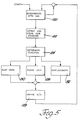
- FIGURES 5 and 7 there is illustrated in block diagram form a control program for controlling the operation of the slave computer 88 to enable it to provide the desired speed control signals to the D/A converter 90 which, in turn, converts these signals to an analog level prior to use by the servomotor 58.
- the auxiliary conveyor 17 is controllably driven in three different modes of operation.
- the primary mode is called the phase-lock mode and is a default mode entered in the absence or completion of any other action or mode.
- the default mode may also be entered directly upon command from the master computer 84.
- the slave computer 88 adjusts the speed control signal emitted by the controller 96 to keep the two incremental encoders 80 and 94.tracking and consequently keep the speeds of the main and auxiliary conveyors 16 and 17 sub- stantially identical.
- the second mode of operation is a displacement mode which is entered by the controller 96 upon receiving a displacement command from the master computer 84.
- the displacement command causes the controller 96 to output a speed control signal to the servomotor.58 which will cause the auxiliary conveyor 17 to either speed up or slow down for a period of time determined by the displacement command so that after this time the downstream glass sheet being conveyed by the auxiliary conveyor 17 will have moved away or toward its companion part on the main conveyor 16.
- the third mode of operation in which the auxiliary conveyor 17 is controlled to operate by the controller 96 is called the slow-down mode.
- the purpose of the slow-down mode is to slow down the auxiliary conveyor 17 during glass sheet removal or pickup from the auxiliary conveyor 17.
- the slow-down mode is timed and initiated from the master computer 84.
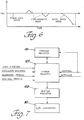
- the auxiliary conveyor 17 slows to a predetermined low speed as shown in FIGURE 6 for a short time and is then returned to the phase-lock mode. This motion is determined from a table in the ROM which is accessed in the slow-down mode of the program of FIGURE 5 and provides a given shift amount for each point of conveyor travel.
- Block 120 represents a one millisecond delay before the main body of the program of FIGURE 5 is entered.
- Block 122 represents the detection and storing of a new command received by the slave computer 88 from the master computer 84 along line 116. At any time during the control program, if a new command is issued from the master computer 84 an interrupt will occur and the interrupt will be serviced. Block 122 represents, therefore, the detection of the particular command after an interrupt has occurred.
- Block 124 represents the determination of which one of the three possible commands has been sent from the master computer 84 so that the slave computer 88 can determine whether to enter its slow-down mode, represented by block 130, the phase-lock mode, represented by block 126, or the displacement mode, represented by block 132.
- An error register 127 is alternately incremented or decremented by square wave signals from the encoders 80 and 94, respectively, after the contents of register 127 are set or initialized at a value representing the desired velocity of both the main and auxiliary conveyors 16 and 17, as shown by the solid horizontal line in FIGURE 6.
- a buffer register 129 receives the count from the error register 127 after the error register 127 receives an appropriate control signal as represented by block 128. The count contained in the buffer register 129 is supplied to the D/A converter 90.
- the square waves are received by the VIA of the slave computer 88 from the encoders 80 and 94.
- the error register 127 contains a binary number corresponding to the velocity of the auxiliary and main conveyors 16 and 17. If the pulses from the encoder 80 appear at a greater frequency than the pulses from the encoder 94, the count contained within the error register 127 will be greater than its set, predetermined amount to cause the magnitude of the speed control signal emitted from the D/A converter 90 to temporarily increase until the count contained within the error register 127 settles to the predetermined amount.
- the magnitude of the speed control signal from the D/A converter 90 will decrease until a greater number of pulses from the encoder 80 cause the count within the error register 127 to settle at the predetermined amount.
- block 128 represents the function of the program of FIGURE 5 to update the signals applied to the D/A converter 90 from the buffer register 129, with the desired count contained within the error register 127.
- Block 130 represents that function of the control program which causes the auxiliary conveyor 17 to operate at the velocity profile as shown in FIGURE 7 with respect to the slow-down mode.
- the block 130 causes the old value stored in the error register 127 to be stored in a storage register 131 and causes the value contained in the error register 127 to be counted down gradually until the minimum, speed of the auxiliary conveyor 17 is reached as indicated by the minimum velocity position of the slow-down curve.
- the old stored values are returned from the storage register 131 to the error register 127 to cause the speed of the auxiliary conveyor 17 to return to that desired speed of the phase-lock mode.
- a positive or negative displacement is indicated by the command from the master computer 84. If a positive displacement is commanded the count within the error register is increased at a fixed rate until half of the command displacement is reached as determined by an acceleration profile generated from the command signal and the internal clock. At this point the speed control signal causes the auxiliary conveyor 17 to move at its maximum speed. The area under the acceleration curve to the maximum speed represents one-half of the displacement commanded. Thereafter the speed control signal from the D/A converter 90 is thereafter gradually reduced at the same rate as the speed was initially increased by a deceleration profile until the phase-lock area underneath the velocity displacement curve represents the entire displacement commanded.
- the VIA of the slave computer 88 causes an interrupt to occur and be serviced at every one millisecond to update a timer contained within the slave computer 88. In like fashion, interrupts also occur and are serviced upon the occurrence of each pulse generated by the encoders 80 and 94 as well as when a command is received by the slave computer 88 from the master computer 84.
Landscapes
- Engineering & Computer Science (AREA)
- Chemical & Material Sciences (AREA)
- Microelectronics & Electronic Packaging (AREA)
- Materials Engineering (AREA)
- Organic Chemistry (AREA)
- Re-Forming, After-Treatment, Cutting And Transporting Of Glass Products (AREA)
- Control Of Conveyors (AREA)
- Rollers For Roller Conveyors For Transfer (AREA)
- Glass Compositions (AREA)
- Vehicle Body Suspensions (AREA)
- Hydrogenated Pyridines (AREA)
Priority Applications (1)
| Application Number | Priority Date | Filing Date | Title |
|---|---|---|---|
| AT83304731T ATE40975T1 (de) | 1982-09-01 | 1983-08-15 | Transportregelung fuer glasscheibenverarbeitungsanlage. |
Applications Claiming Priority (2)
| Application Number | Priority Date | Filing Date | Title |
|---|---|---|---|
| US06/414,088 US4475937A (en) | 1982-09-01 | 1982-09-01 | Conveyor controller for glass sheet processing equipment |
| US414088 | 1982-09-01 |
Publications (3)
| Publication Number | Publication Date |
|---|---|
| EP0103421A2 true EP0103421A2 (de) | 1984-03-21 |
| EP0103421A3 EP0103421A3 (en) | 1985-03-27 |
| EP0103421B1 EP0103421B1 (de) | 1989-03-01 |
Family
ID=23639908
Family Applications (1)
| Application Number | Title | Priority Date | Filing Date |
|---|---|---|---|
| EP83304731A Expired EP0103421B1 (de) | 1982-09-01 | 1983-08-15 | Transportregelung für Glasscheibenverarbeitungsanlage |
Country Status (16)
| Country | Link |
|---|---|
| US (1) | US4475937A (de) |
| EP (1) | EP0103421B1 (de) |
| JP (1) | JPS5988334A (de) |
| KR (1) | KR880002459B1 (de) |
| AT (1) | ATE40975T1 (de) |
| AU (1) | AU567502B2 (de) |
| BR (1) | BR8304759A (de) |
| CA (1) | CA1213338A (de) |
| DE (1) | DE3379263D1 (de) |
| ES (1) | ES8500196A1 (de) |
| FI (1) | FI74938C (de) |
| IE (1) | IE54449B1 (de) |
| IN (1) | IN160111B (de) |
| MX (1) | MX155614A (de) |
| NZ (1) | NZ205266A (de) |
| ZA (1) | ZA836157B (de) |
Cited By (5)
| Publication number | Priority date | Publication date | Assignee | Title |
|---|---|---|---|---|
| EP0229337A1 (de) * | 1985-12-19 | 1987-07-22 | Ppg Industries, Inc. | Scheibenpositionierungssystem |
| FR2600997A1 (fr) * | 1986-07-07 | 1988-01-08 | Nippon Sheet Glass Co Ltd | Systeme de commande de la vitesse de transport pour installation de recuisson de verre plat |
| EP0267850A3 (de) * | 1986-11-12 | 1989-02-22 | Saint-Gobain Vitrage International | Auffindung einer auf die Verformungstemperatur aufgeheizten Glasplatte |
| EP0625380A1 (de) * | 1993-05-18 | 1994-11-23 | Siemens Aktiengesellschaft | Separierverfahren |
| EP0739315A4 (de) * | 1993-09-13 | 1996-07-16 | Glasstech Inc | Vorrichtung und verfahren zur positionierung von glasplatten |
Families Citing this family (26)
| Publication number | Priority date | Publication date | Assignee | Title |
|---|---|---|---|---|
| DE3319247C2 (de) * | 1983-05-27 | 1986-07-17 | E.C.H. Will (Gmbh & Co), 2000 Hamburg | Verfahren und Vorrichtung zum Fördern von Blattlagen zu einer Weiterverarbeitungsmaschine |
| FR2571143B1 (fr) * | 1984-10-02 | 1988-03-25 | Languedoc Verrerie | Procede et dispositif de controle sans contact d'objets fabriques automatiquement a haute cadence |
| JPS6241728A (ja) * | 1985-08-19 | 1987-02-23 | Nippon Sheet Glass Co Ltd | 板ガラスの加熱曲げ装置 |
| US4632688A (en) * | 1985-11-08 | 1986-12-30 | Libbey-Owens-Ford Company | Apparatus and method for treating glass sheets |
| US4782449A (en) * | 1986-04-17 | 1988-11-01 | Glasstech, Inc. | Position controller for glass sheet processing system |
| US4825376A (en) * | 1986-04-17 | 1989-04-25 | Glasstech International L.P. | Controller for glass sheet processing system |
| FR2601667B1 (fr) * | 1986-07-16 | 1988-09-16 | Saint Gobain Vitrage | Positionnement des plaques de verre en vue de leur bombage |
| GB2193709B (en) * | 1986-07-28 | 1989-12-13 | Libbey Owens Ford Co | Apparatus for aligning glass sheets in a production line |
| JPS6387408A (ja) * | 1986-09-29 | 1988-04-18 | Nippon Sheet Glass Co Ltd | 搬送速度制御装置 |
| FR2606383B1 (fr) * | 1986-11-06 | 1989-01-13 | Saint Gobain Vitrage | Positionnement de plaques de verre en vue notamment de leur bombage |
| US4767434A (en) * | 1987-09-29 | 1988-08-30 | Ppg Industries, Inc. | Horizontal press bending pickup and delivery system |
| IL84383A (en) * | 1987-11-06 | 1994-08-26 | Kyro Oy | Apparatus for cutting glass blanks |
| US4775404A (en) * | 1987-11-17 | 1988-10-04 | Glasstech, Inc. | Apparatus for registering glass sheet on glass sheet shaping tool |
| US4946523A (en) * | 1988-12-22 | 1990-08-07 | Ford Motor Company | Method and apparatus for use in manufacturing safety glass laminates |
| US5147439A (en) * | 1990-05-01 | 1992-09-15 | Glasstech, Inc. | Variable pressure gas jet system for lifting and forming glass sheets |
| US5411128A (en) * | 1994-01-03 | 1995-05-02 | Vild; Michael J. | Heated glass sheet positioning on roll conveyor |
| US5833729A (en) * | 1996-12-16 | 1998-11-10 | Ppg Industries, Inc. | Method and apparatus for bending glass sheets |
| US20050044892A1 (en) * | 2003-08-28 | 2005-03-03 | George Stephan P. | Method and apparatus for heating glass sheets |
| DE102007043567B3 (de) * | 2007-09-13 | 2008-10-02 | Grenzebach Maschinenbau Gmbh | Vorrichtung und Verfahren zum Trennen von Glasplatten |
| JP5228445B2 (ja) * | 2007-11-01 | 2013-07-03 | セントラル硝子株式会社 | ガラスリボンの搬送補助装置 |
| US9896369B2 (en) * | 2014-11-24 | 2018-02-20 | Glasstech, Inc. | Glass sheet forming and annealing providing edge stress control |
| TWI729020B (zh) * | 2015-11-02 | 2021-06-01 | 美商玻璃技術股份有限公司 | 玻璃片材定位設備及方法以及玻璃片材加工系統 |
| CN106977090B (zh) * | 2017-03-24 | 2019-10-11 | 中国建材国际工程集团有限公司 | 浮法玻璃控制等片方法及系统 |
| CN112551915A (zh) * | 2019-09-10 | 2021-03-26 | 苏州科洛德激光科技有限公司 | 大尺寸玻璃激光除膜方法及装置 |
| CN112919794B (zh) * | 2021-03-23 | 2022-08-12 | 洛玻集团洛阳龙昊玻璃有限公司 | 玻璃生产线用辅助行进装置 |
| CN118004757B (zh) * | 2024-03-28 | 2025-09-16 | 漳州旗滨光伏新能源科技有限公司 | 排距方法 |
Family Cites Families (6)
| Publication number | Priority date | Publication date | Assignee | Title |
|---|---|---|---|---|
| US3894627A (en) * | 1973-06-01 | 1975-07-15 | Fmc Corp | Conveyor for interspacing articles |
| US3992182A (en) * | 1974-09-18 | 1976-11-16 | Ppg Industries, Inc. | Conveying sheets at non-uniform speed |
| US4133667A (en) * | 1978-03-20 | 1979-01-09 | Nitschke John Stephen | Conveyor drive mechanism for a glass sheet manufacturing system |
| CA1125890A (en) * | 1979-10-18 | 1982-06-15 | John S. Nitschke | Conveyor drive system for a glass sheet manufacturing system |
| US4360374A (en) * | 1980-11-24 | 1982-11-23 | Nitschke John Stephen | Roll operator for glass sheet conveyor of bending system |
| US4364766A (en) * | 1981-05-01 | 1982-12-21 | Nitschke John Stephen | Control system for monitoring and controlling the processing of glass sheets in a glass processing environment |
-
1982
- 1982-09-01 US US06/414,088 patent/US4475937A/en not_active Expired - Lifetime
-
1983
- 1983-08-08 IE IE1862/83A patent/IE54449B1/en not_active IP Right Cessation
- 1983-08-10 AU AU17844/83A patent/AU567502B2/en not_active Ceased
- 1983-08-15 AT AT83304731T patent/ATE40975T1/de not_active IP Right Cessation
- 1983-08-15 EP EP83304731A patent/EP0103421B1/de not_active Expired
- 1983-08-15 DE DE8383304731T patent/DE3379263D1/de not_active Expired
- 1983-08-15 NZ NZ205266A patent/NZ205266A/en unknown
- 1983-08-19 ZA ZA836157A patent/ZA836157B/xx unknown
- 1983-08-26 CA CA000435472A patent/CA1213338A/en not_active Expired
- 1983-08-30 KR KR1019830004046A patent/KR880002459B1/ko not_active Expired
- 1983-08-31 ES ES525277A patent/ES8500196A1/es not_active Expired
- 1983-08-31 IN IN1056/CAL/83A patent/IN160111B/en unknown
- 1983-08-31 JP JP58160225A patent/JPS5988334A/ja active Granted
- 1983-08-31 FI FI833103A patent/FI74938C/fi not_active IP Right Cessation
- 1983-08-31 MX MX198569A patent/MX155614A/es unknown
- 1983-08-31 BR BR8304759A patent/BR8304759A/pt not_active IP Right Cessation
Cited By (6)
| Publication number | Priority date | Publication date | Assignee | Title |
|---|---|---|---|---|
| EP0229337A1 (de) * | 1985-12-19 | 1987-07-22 | Ppg Industries, Inc. | Scheibenpositionierungssystem |
| FR2600997A1 (fr) * | 1986-07-07 | 1988-01-08 | Nippon Sheet Glass Co Ltd | Systeme de commande de la vitesse de transport pour installation de recuisson de verre plat |
| BE1003060A5 (fr) * | 1986-07-07 | 1991-11-12 | Nippon Sheet Glass Co Ltd | Systeme de commande de la vitesse de transport pour installation de recuisson de verre plat. |
| EP0267850A3 (de) * | 1986-11-12 | 1989-02-22 | Saint-Gobain Vitrage International | Auffindung einer auf die Verformungstemperatur aufgeheizten Glasplatte |
| EP0625380A1 (de) * | 1993-05-18 | 1994-11-23 | Siemens Aktiengesellschaft | Separierverfahren |
| EP0739315A4 (de) * | 1993-09-13 | 1996-07-16 | Glasstech Inc | Vorrichtung und verfahren zur positionierung von glasplatten |
Also Published As
| Publication number | Publication date |
|---|---|
| IN160111B (de) | 1987-06-27 |
| EP0103421A3 (en) | 1985-03-27 |
| JPS5988334A (ja) | 1984-05-22 |
| ES525277A0 (es) | 1984-10-01 |
| ZA836157B (en) | 1984-07-25 |
| KR880002459B1 (ko) | 1988-11-14 |
| AU1784483A (en) | 1984-03-08 |
| NZ205266A (en) | 1986-11-12 |
| CA1213338A (en) | 1986-10-28 |
| US4475937A (en) | 1984-10-09 |
| AU567502B2 (en) | 1987-11-26 |
| FI833103A7 (fi) | 1984-03-02 |
| BR8304759A (pt) | 1984-04-10 |
| KR840006166A (ko) | 1984-11-22 |
| IE831862L (en) | 1984-03-01 |
| ES8500196A1 (es) | 1984-10-01 |
| FI74938C (fi) | 1988-04-11 |
| MX155614A (es) | 1988-04-06 |
| ATE40975T1 (de) | 1989-03-15 |
| FI833103A0 (fi) | 1983-08-31 |
| IE54449B1 (en) | 1989-10-11 |
| FI74938B (fi) | 1987-12-31 |
| JPS6230143B2 (de) | 1987-06-30 |
| DE3379263D1 (en) | 1989-04-06 |
| EP0103421B1 (de) | 1989-03-01 |
Similar Documents
| Publication | Publication Date | Title |
|---|---|---|
| US4475937A (en) | Conveyor controller for glass sheet processing equipment | |
| US4364766A (en) | Control system for monitoring and controlling the processing of glass sheets in a glass processing environment | |
| US4690269A (en) | Apparatus for transferring shaped articles | |
| CN109855425B (zh) | 一种步进梁加热炉传动送料装置及方法 | |
| US4682684A (en) | Method and an arrangement for the feeding of objects | |
| EP0798242B1 (de) | Verfahren zum Ordnen von Nahrungsmitteln und Gerät dafür | |
| CZ247490A3 (cs) | Zařízení pro ohýbání skleněných tabulí | |
| US4488846A (en) | Process and device for feeding glass sheets to a furnace | |
| EP1300351B1 (de) | Verfahren und Vorrichtung zum geordneten Abführen von ungeordnet zugeführten Produkten | |
| US4360374A (en) | Roll operator for glass sheet conveyor of bending system | |
| IT8348269A1 (it) | Macchina di molatura dei bordi di una lastra di vetro | |
| US4915722A (en) | Process and apparatus for manufacturing a curved sheet of glass | |
| US5147439A (en) | Variable pressure gas jet system for lifting and forming glass sheets | |
| US4199291A (en) | Velocity compensator assembly in a horizontal article conveyor system | |
| US20030097821A1 (en) | Method and device for synchronizing motion for insert feeders in an insertion system | |
| IE56042B1 (en) | Apparatus and method for locally heating conveyed glass sheets | |
| JPS6149255B2 (de) | ||
| EP1003675B1 (de) | Transfermechanismus | |
| CN108870957A (zh) | 一种镁合金型材塑性变形机前自动加热炉 | |
| CN2182376Y (zh) | 立式干燥器用的砖坯送入装置 | |
| US3815433A (en) | Drive mechanism for a conveyor device for producing an intermittent conveying movement in accordance with a desired pattern of movement | |
| CN223133093U (zh) | 一种自动送片平台 | |
| WO1991012211A1 (en) | Variable pressure gas jet system for lifting and forming glass sheets | |
| GB2059941A (en) | Tempering apparatus for glass sheets | |
| CN112423417A (zh) | 一种中频加热设备 |
Legal Events
| Date | Code | Title | Description |
|---|---|---|---|
| PUAI | Public reference made under article 153(3) epc to a published international application that has entered the european phase |
Free format text: ORIGINAL CODE: 0009012 |
|
| AK | Designated contracting states |
Designated state(s): AT BE CH DE FR GB IT LI LU NL SE |
|
| PUAL | Search report despatched |
Free format text: ORIGINAL CODE: 0009013 |
|
| AK | Designated contracting states |
Designated state(s): AT BE CH DE FR GB IT LI LU NL SE |
|
| 17P | Request for examination filed |
Effective date: 19850913 |
|
| 17Q | First examination report despatched |
Effective date: 19860704 |
|
| RAP1 | Party data changed (applicant data changed or rights of an application transferred) |
Owner name: GLASSTECH, INC. |
|
| RIN1 | Information on inventor provided before grant (corrected) |
Inventor name: NITSCHKE, JOHN STEPHEN |
|
| D17Q | First examination report despatched (deleted) | ||
| GRAA | (expected) grant |
Free format text: ORIGINAL CODE: 0009210 |
|
| AK | Designated contracting states |
Kind code of ref document: B1 Designated state(s): AT BE CH DE FR GB IT LI LU NL SE |
|
| REF | Corresponds to: |
Ref document number: 40975 Country of ref document: AT Date of ref document: 19890315 Kind code of ref document: T |
|
| REF | Corresponds to: |
Ref document number: 3379263 Country of ref document: DE Date of ref document: 19890406 |
|
| ET | Fr: translation filed | ||
| ITF | It: translation for a ep patent filed | ||
| PLBE | No opposition filed within time limit |
Free format text: ORIGINAL CODE: 0009261 |
|
| STAA | Information on the status of an ep patent application or granted ep patent |
Free format text: STATUS: NO OPPOSITION FILED WITHIN TIME LIMIT |
|
| 26N | No opposition filed | ||
| ITTA | It: last paid annual fee | ||
| EPTA | Lu: last paid annual fee | ||
| EAL | Se: european patent in force in sweden |
Ref document number: 83304731.9 |
|
| PGFP | Annual fee paid to national office [announced via postgrant information from national office to epo] |
Ref country code: NL Payment date: 19970625 Year of fee payment: 15 |
|
| PGFP | Annual fee paid to national office [announced via postgrant information from national office to epo] |
Ref country code: SE Payment date: 19970717 Year of fee payment: 15 |
|
| PGFP | Annual fee paid to national office [announced via postgrant information from national office to epo] |
Ref country code: AT Payment date: 19970723 Year of fee payment: 15 |
|
| PG25 | Lapsed in a contracting state [announced via postgrant information from national office to epo] |
Ref country code: AT Free format text: LAPSE BECAUSE OF NON-PAYMENT OF DUE FEES Effective date: 19980815 |
|
| PG25 | Lapsed in a contracting state [announced via postgrant information from national office to epo] |
Ref country code: SE Free format text: LAPSE BECAUSE OF NON-PAYMENT OF DUE FEES Effective date: 19980816 |
|
| PG25 | Lapsed in a contracting state [announced via postgrant information from national office to epo] |
Ref country code: NL Free format text: LAPSE BECAUSE OF NON-PAYMENT OF DUE FEES Effective date: 19990301 |
|
| EUG | Se: european patent has lapsed |
Ref document number: 83304731.9 |
|
| NLV4 | Nl: lapsed or anulled due to non-payment of the annual fee |
Effective date: 19990301 |
|
| PGFP | Annual fee paid to national office [announced via postgrant information from national office to epo] |
Ref country code: LU Payment date: 20010627 Year of fee payment: 19 |
|
| PGFP | Annual fee paid to national office [announced via postgrant information from national office to epo] |
Ref country code: GB Payment date: 20010629 Year of fee payment: 19 |
|
| PGFP | Annual fee paid to national office [announced via postgrant information from national office to epo] |
Ref country code: CH Payment date: 20010920 Year of fee payment: 19 |
|
| REG | Reference to a national code |
Ref country code: GB Ref legal event code: IF02 |
|
| PGFP | Annual fee paid to national office [announced via postgrant information from national office to epo] |
Ref country code: FR Payment date: 20020805 Year of fee payment: 20 |
|
| PG25 | Lapsed in a contracting state [announced via postgrant information from national office to epo] |
Ref country code: LU Free format text: LAPSE BECAUSE OF NON-PAYMENT OF DUE FEES Effective date: 20020815 Ref country code: GB Free format text: LAPSE BECAUSE OF NON-PAYMENT OF DUE FEES Effective date: 20020815 |
|
| PGFP | Annual fee paid to national office [announced via postgrant information from national office to epo] |
Ref country code: DE Payment date: 20020830 Year of fee payment: 20 |
|
| PG25 | Lapsed in a contracting state [announced via postgrant information from national office to epo] |
Ref country code: LI Free format text: LAPSE BECAUSE OF NON-PAYMENT OF DUE FEES Effective date: 20020831 Ref country code: CH Free format text: LAPSE BECAUSE OF NON-PAYMENT OF DUE FEES Effective date: 20020831 |
|
| PGFP | Annual fee paid to national office [announced via postgrant information from national office to epo] |
Ref country code: BE Payment date: 20020913 Year of fee payment: 20 |
|
| GBPC | Gb: european patent ceased through non-payment of renewal fee |
Effective date: 20020815 |
|
| REG | Reference to a national code |
Ref country code: CH Ref legal event code: PL |