EP0103318B1 - Vorrichtung zur Herstellung der Wülste und Wasserfalze an Dachrinnenwinkeln - Google Patents
Vorrichtung zur Herstellung der Wülste und Wasserfalze an Dachrinnenwinkeln Download PDFInfo
- Publication number
- EP0103318B1 EP0103318B1 EP83201151A EP83201151A EP0103318B1 EP 0103318 B1 EP0103318 B1 EP 0103318B1 EP 83201151 A EP83201151 A EP 83201151A EP 83201151 A EP83201151 A EP 83201151A EP 0103318 B1 EP0103318 B1 EP 0103318B1
- Authority
- EP
- European Patent Office
- Prior art keywords
- water
- die member
- raised
- longitudinal edge
- lowered
- Prior art date
- Legal status (The legal status is an assumption and is not a legal conclusion. Google has not performed a legal analysis and makes no representation as to the accuracy of the status listed.)
- Expired
Links
- 239000011324 bead Substances 0.000 title claims abstract description 19
- XLYOFNOQVPJJNP-UHFFFAOYSA-N water Substances O XLYOFNOQVPJJNP-UHFFFAOYSA-N 0.000 title description 20
- 238000005452 bending Methods 0.000 claims abstract description 14
- 238000004804 winding Methods 0.000 description 13
- 238000004519 manufacturing process Methods 0.000 description 7
- 230000015572 biosynthetic process Effects 0.000 description 2
- 230000001154 acute effect Effects 0.000 description 1
- 230000006978 adaptation Effects 0.000 description 1
- 230000007774 longterm Effects 0.000 description 1
- 239000007769 metal material Substances 0.000 description 1
- 238000000465 moulding Methods 0.000 description 1
- 238000007493 shaping process Methods 0.000 description 1
- 238000005476 soldering Methods 0.000 description 1
- 238000009966 trimming Methods 0.000 description 1
- 238000003466 welding Methods 0.000 description 1
Images


Classifications
-
- B—PERFORMING OPERATIONS; TRANSPORTING
- B21—MECHANICAL METAL-WORKING WITHOUT ESSENTIALLY REMOVING MATERIAL; PUNCHING METAL
- B21D—WORKING OR PROCESSING OF SHEET METAL OR METAL TUBES, RODS OR PROFILES WITHOUT ESSENTIALLY REMOVING MATERIAL; PUNCHING METAL
- B21D19/00—Flanging or other edge treatment, e.g. of tubes
- B21D19/12—Edge-curling
Definitions
- the invention relates to a device for producing the beads and water seams by automatic winding or bending of the free overhanging, trimmed longitudinal edge areas of the blanks formed by deep drawing for one-piece gutter angles, the side walls of which are formed in a circular arc in the area of the corner connection of the abutting gutter angle pieces.
- a gutter angle for connecting semicircular gutters is to be found in DE-U-78 11 514 provided, which is produced by deep-drawing sheet metal material and in which the side walls are each designed in the form of a circular arc in the region of their corners.
- free edge areas remain on the longitudinal edges, which, after appropriate trimming, are rolled into beads or water folds are folded.
- the device of the type mentioned at the beginning comprises a lower tool and an upper tool, the lower tool consisting of a fixed lower part which is adapted to the outer profile of the blank and an adjacent one on the side of the water fold to be formed, raised / lowerable raised part.
- the upper tool is formed by a liftable / lowerable upper mold part which is adapted to the inner profile of the blank and can be clamped to the lower molded part, in which a liftable / lowerable support beam is fitted in a recess on the side of the water fold to be formed.
- a rotating winding rod provided with a longitudinal slit, which can be pushed onto the edges of the free longitudinal edge regions, and which can be moved longitudinally and transversely.
- a longitudinally displaceable, rotatable bending rod provided with a longitudinal slot and slidable onto the edges of the free longitudinal edge regions.
- the raised part and the support beam each consist of two components that can be lifted / lowered in the corners.
- a lifting / lowering support jaw is arranged for clamping the free longitudinal edge areas, each of which has a U-shaped recess running parallel to the axis of the blank, so that in the clamped position there is a channel between the two support jaws, into which the winding bars can be inserted and pushed onto the longitudinal edge areas.
- the lower and the upper molded part are interchangeable, so that an adaptation to different profiles of the blanks for gutter angles is possible.
- the winding rods and the bending rods are arranged on their longitudinal slides together with their drives, and the longitudinal slides for the winding rods are arranged on cross slides, the cross slides being movable on a track inclined towards the lower molded part.
- the molded part 8 which forms part of the upper tool and can be raised / lowered with the aid of the cylinder 7 and corresponds to the inner profile of the blank 1, is clamped against the lower molded part 5.
- the support bar 10 which can be raised / lowered via the cylinder 9 and forms the other part of the upper tool, is then lowered into the recess 11 of the molded part 8 located on the side of the forming water fold and then that on the side of the water fold to be formed next to the lower molded part 5 located, can be raised / lowered by the cylinder 12, raised form part 13, whereby the longitudinal edge regions 3, 3 'provided for the water rebate formation are placed approximately parallel to the vertical central plane of the blank 1.
- the blank 27, which is formed by deep drawing and is trimmed on its longitudinal edges and is used to produce an inside gutter angle, the free longitudinal edge regions 28, 28 ', 29, 29' of which project approximately horizontally with respect to the vertical central plane, is arranged in a stationary manner in the base plate 30 lower molded part 31 of the multi-part lower tool, the profile of which corresponds to the outer profile of the blank 27, inserted and clamped against the lower molded part 31 by means of the molded part 33, which forms part of the upper tool and can be raised / lowered by the cylinder 32 and corresponds to the internal profile of the blank 27 .
- the raisable / lowerable two support beam parts 35, 35 ' which form the other part of the upper tool and which are arranged on the side of the water fold to be formed, are lowered into the recess 36 of the molded part 33 via the cylinders 34, 34'.
- the cylinders 37, 37 ' are used to raise and lower the two raised positioning parts 38, 38' one after the other on the side of the water fold to be formed next to the lower mold part 31 and forming part of the lower tool, so that the free longitudinal edge regions 28, 28 'of the blank 27 are formed approximately parallel to the vertical central plane so that they overlap in the corner area.
- the winding bars 48, 48 ' are rotated by the drives 49, 49' and the bending bar 47 by the drive 50, whereby the beads 51, 51 'and a water fold 52 are formed.
- the winding bars 48, 48 ' which are each located on a cross slide 53, 53', are moved towards the gutter angle on an inclined plane.
- the second water fold 52 ' is then bent by the bending bar 47' to form an overlap in the corner area.
- the molded parts 33, 35, 35 ', 41' forming the upper tool and the cylinders 32, 34, 34 'required for their actuation are fastened to the holding plate 55 attached to the cross member 54.
Landscapes
- Engineering & Computer Science (AREA)
- Mechanical Engineering (AREA)
- Making Paper Articles (AREA)
- Cosmetics (AREA)
- Conveying And Assembling Of Building Elements In Situ (AREA)
- Roof Covering Using Slabs Or Stiff Sheets (AREA)
- Pinball Game Machines (AREA)
- Impact Printers (AREA)
- Manufacturing Of Tubular Articles Or Embedded Moulded Articles (AREA)
- Moulds, Cores, Or Mandrels (AREA)
- Processing Of Meat And Fish (AREA)
- Wire Processing (AREA)
- Perforating, Stamping-Out Or Severing By Means Other Than Cutting (AREA)
- Cartons (AREA)
- Developing Agents For Electrophotography (AREA)
- Transition And Organic Metals Composition Catalysts For Addition Polymerization (AREA)
- Press-Shaping Or Shaping Using Conveyers (AREA)
- Bending Of Plates, Rods, And Pipes (AREA)
- Special Spraying Apparatus (AREA)
- Mounting, Exchange, And Manufacturing Of Dies (AREA)
Description
- Die Erfindung betrifft eine Vorrichtung zur Herstellung der Wülste und Wasserfalze durch automatisches Wickeln bzw. Biegen der freien überstehenden, besäumten Längsrandbereiche der durch Tiefziehen geformten Rohlinge für einteilige Dachrinnenwinkel, deren Seitenwände im Bereich der Eckverbindung der aufeinanderstossenden Dachrinnenwinkelstücke kreisbogenförmig ausgebildet sind.
- Um das bei der Herstellung von Dachrinnenwinkeln aus zwei spitzwinklig gegeneinanderstossenden halbrunden Dachrinnenstücken übliche Löten oder Schweissen der in Gehrungsrichtung verlaufenden Verbindungsnaht wegen der damit verbundenen Nachteile bezüglich Montage und Langzeitdichtigkeit zu vermeiden, ist in dem DE-U-78 11 514 ein Dachrinnenwinkel zur Verbindung halbrunder Dachrinnen vorgesehen, der durch Tiefziehen von Blechmaterial hergestellt und bei dem die Seitenwände im Bereich ihrer Ecken jeweils kreisbogenförmig gestaltet sind. Bei einem solchen Dachrinnenwinkel bleiben an den Längsrändern freie Randbereiche überstehen, die nach entsprechendem Besäumen zu Wülsten gewickelt bzw. Wasserfalzen angekantet werden. Abgesehen davon, dass diese Biegearbeiten im allgemeinen unter Anwendung herkömmlicher Dachdecker-Werkzeuge und -Hilfsmittel durchgeführt werden, ist auch schon versucht worden, Wülste und Wasserfalze unter Einsatz geeigneter Maschinen zu wickeln bzw. anzukanten, wobei in nachteiliger Weise sowohl für die Herstellung der Wülste als auch für die Herstellung der Wasserfalze jeweils mehrere Arbeitsgänge notwendig sind. Das bedeutet, einen relativ hohen Aufwand an manueller Tätigkeit und Zeit und entspricht nicht einer nach zeitgemässen Gesichtspunkten durchzuführenden Fertigung.
- Es ist Aufgabe der vorliegenden Erfindung, das Formen der Wülste und Wasserfalze an durch Tiefziehen hergestellten Rohlingen für einteilige Dachrinnenwinkel schnell, einfach und mit möglichst niedrigem Aufwand durchzuführen.
- Die Lösung dieser Aufgabe besteht darin, dass die Vorrichtung der eingangs genannten Art ein Unterwerkzeug und ein Oberwerkzeug umfasst, wobei das Unterwerkzeug aus einem ortsfest angeordneten, dem Aussenprofil des Rohlings angepassten, unteren Formteil und einem neben diesem auf der Seite des zu formenden Wasserfalzes angeordneten, heb-/senkbaren Hochstellformteil besteht. Das Oberwerkzeug ist durch ein heb-/senkbares, dem Innenprofil des Rohlings angepasstes, auf das untere Formteil spannbares, oberes Formteil gebildet, bei dem auf der Seite des zu formenden Wasserfalzes in einer Ausnehmung ein heb-/senkbarer Stützbalken angebracht ist. Auf den Seiten der zu wickelnden Wülste befindet sich jeweils ein mit einem Längsschlitz versehener, auf die Kanten der freien Längsrandbereiche aufschiebbarer, längs- und querverschieblicher, drehbarer Wickelstab. Auf den Seiten der zu formenden Wasserfalze ist jeweils ein mit einem Längsschlitz versehener, auf die Kanten der freien Längsrandbereiche aufschiebbarer, längsverschieblicher, drehbarer Biegestab angeordnet.
- Zur Herstellung der Wasserfalze an Rohlingen für Dachrinneninnenwinkel bestehen das Hochstellformteil und der Stützbalken jeweils aus zwei im Bereich der Ecken getrennten, heb-/senkbaren Bauteilen.
- Zweckmässigerweise ist zur Herstellung der Wülste an Rohlingen für Dachrinneninnenwinkel im Bereich der Ecken des unteren und oberen Formteils jeweilseine heb-/senkbare Stützbacke für das Einklemmen der freien Längsrandbereiche angeordnet, die jweils eine parallel zur Achse des Rohlings verlaufende U-förmige Ausnehmung aufweisen, so dass in Klemmstellung ein Kanal zwischen beiden Stützbacken vorhanden ist, in den die Wickelstäbe eingefahren und auf die Längsrandbereiche aufgeschoben werden können.
- Nach einer Ausgestaltung der Erfindung sind das untere und das obere Formteil auswechselbar, so dass eine Anpassung an unterschiedliche Profile der Rohlinge für Dachrinnenwinkel möglich ist.
- Im Rahmen der besonderen Ausgestaltung der erfindungsgemässen Vorrichtung sind die Wikkelstäbe und die Biegestäbe zusammen mit ihren Antrieben auf Längsschlitten und die Längsschlitten für die Wickelstäbe auf Querschlitten angeordnet, wobei die Querschlitten auf einer zum unteren Formteil hin geneigt angebrachten Bahn verfahrbar sind.
- Die mit der Erfindung erzielten Vorteile bestehen insbesondere darin, dass die an tiefgezogenen Rohlingen für Dachrinnenwinkel anzuformenden Wülste und Wasserfalze schnell, einfach und mit vergleichsweise geringem Aufwand herstellbar sind. Es ist lediglich erforderlich, dass die Rohlinge von Hand in das untere Formteil eingelegt werden; danach laufen alle Formgebungsvorgänge automatisch ab.
- Im folgenden ist jeweils ein Ausführungsbeispiel für einen Dachrinnenaussenwinkel und einen Dachrinneninnenwinkel beschrieben und anhand der Zeichnungen näher erläutert.
- Es zeigen
- Fig. 1 eine Draufsicht auf die Vorrichtung von Dachrinnenaussenwinkeln
- Fig. 2 einen Schnitt entlang der Schnittlinie I-I der Fig. 1
- Fig. 3 eine Draufsicht auf die Vorrichtung bei abgenommenem Oberteil
- Fig. 4 eine isometrische Darstellung von Ober-und Unterwerkzeug.
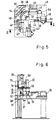
- Der durch Tiefziehen geformte und an seinen Längsrändern besäumte, für die Herstellung der Wülste und Wasserfalze vorgesehene Rohling 1 eines Dachrinnenaussenwinkels, dessen freie Längsrandbereiche 2, 2', 3, 3', bezogen auf die senkrechte Mittelebene, etwa horizontal abstehen, wird in das auf der Grundplatte 4 ortsfest angeordnete, auswechselbare, das gleiche Profil wie das Aussenprofil des Rohlings 1 aufweisende Formteil 5 des mehrteiligen Unterwerkzeugs eingelegt. Durch eine entsprechende Steuerung wird zunächst das, einen Teil des Oberwerkzeugs bildende, mit Hilfe des Zylinders 7 heb-/senkbare, dem Innenprofil des Rohlings 1 entsprechende Formteil 8 gegen das untere Formteil 5 gespannt. Anschliessend wird der über den Zylinder 9 heb-/ senkbare, den anderen Teil des Oberwerkzeugs bildende Stützbalken 10 in die auf der Seite des formenden Wasserfalzes befindliche Ausnehmung 11 des Formteils 8 abgesenkt und dann das auf der Seite des zu formenden Wasserfalzes neben dem unteren Formteil 5 befindliche, durch den Zylinder 12 heb-/senkbare, Hochstellformteil 13 hochgefahren, wodurch die für die Wasserfalzbildung vorgesehenen Längsrandbereiche 3, 3' etwa parallel zur senkrechten Mittelebene des Rohlings 1 gestellt werden. Nachdem der Stützbalken 10 und das Hochstellformteil 13 wieder in Ausgangsstellung gefahren sind, fahren die auf den Führungen 14,14', 15, 15' gelagerten Längsschlitten 16,16' mit Hilfe der Zylinder 17,17' ein, so dass die über die Antriebe 18, 18', 19,19' drehbaren Wickelstäbe 20, 20' und Biegestäbe 21,21' mit ihren Längsschlitzen auf die Kanten der freien Längsrandbereiche, 2, 2', 3, 3' des Rohlings 1 aufgeschoben werden. Es werden zunächst der eine und dann der andere der freien Längsrandbereiche 2, 2' zu jeweils einem Wulst geformt, wobei die die Wickelstäbe 20, 20' tragenden Querschlitten 22, 22' beim Wickeln der Wülste 23, 23' auf einer schiefen Ebene zum Dachrinnenwinkel hin bewegt werden. Danach werden die hochgestellten freien Längsrandbereiche 3, 3' zu Wasserfalzen 24, 24' gebogen. Anschliessend fahren die Wikkelstäbe 20, 20', die Biegestäbe 21, 21' und das Formteil 8 in die Ausgangsstellung. Das Formteil 8 und die für die Betätigung des Formteils 10 und des Stützbalkens 12 vorgesehenen Zylinder 7, 9 sind an der an dem Querträger 25 angebrachten Halteplatte 26 befestigt.
- Es zeigen
- Fig. 5 eine Draufsicht auf die Vorrichtung zur Herstellung von Dachrinneninnenwinkeln
- Fig. 6 einen Schnitt entlang der Schnittlinie II―II der Fig. 5
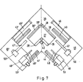
- Fig. 7 eine Draufsicht auf die Vorrichtung bei abgenommenem Oberteil
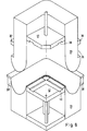
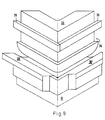
- Fig. 8 und 9 eine isometrische Darstellung von Ober- und Unterwerkzeug von Vorder- und Rückseite.
- Der durch Tiefziehen geformte und an seinen Längsrändern besäumte, zur Herstellung eines Dachrinneninnenwinkels dienende Rohling 27, dessen freie Längsrandbereiche 28, 28', 29, 29', bezogen auf die senkrechte Mittelebene, etwa horizontal abstehen, wird in das auf der Grundplatte 30 ortsfest angeordnete untere Formteil 31 des mehrteiligen Unterwerkzeugs, dessen Profil dem Aussenprofil des Rohlings 27 entspricht, eingelegt und mittels des, einen Teil des Oberwerkzeugs bildenden, durch den Zylinder 32 heb-/senkbaren, dem Innenprofil des Rohlings 27 entsprechenden Formteils 33 gegen das untere Formteil 31 gespannt. Danach werden über den Zylinder 34, 34' die den anderen Teil des Oberwerkzeugs bildenden, auf der Seite des zu formenden Wasserfalzes angeordneten heb-/ senkbaren zwei Stützbalkenteile 35, 35' in die Ausnehmung 36 des Formteils 33 abgesenkt. Anschliessend werden über die Zylinder 37, 37' die auf der Seite des zu formenden Wasserfalzes neben dem unteren Formteil 31 angebrachten, einen Teil des Unterwerkzeugs bildenden heb-/senkbaren, zwei Hochstellformteile 38, 38' nacheinander hochgefahren, so dass die freien Längsrandbereiche 28, 28' des Rohlings 27 etwa parallel zur senkrechten Mittelebene stehend so geformt werden, dass sie sich im Eckbereich überlappen. Gleichzeitig werden, die für die Wulstbildung vorgesehenen freien Längsrandbereiche 29, 29' zwischen den jeweils mit einer U-förmigen, parallel zur Achse des Rohlings 27 verlaufenden Ausnehmung 39, 40 versehenen, heb-/senkbaren Stützbacken 41, 42 festgeklemmt. Nachdem die Stützbalkenteile 35, 35' und die Hochstellformteile 38, 38' wieder in Ausgangsstellung gefahren sind, fahren die auf den Führungen 43, 43' 44, 44' gelagerten Längsschlitten 45, 45' mittels der Zylinder 46, 46' ein, so dass die Längsschlitze der Biegestäbe 47, 47' und Wickelstäbe 48, 48' auf die Kanten der freien Längsrandbereiche 28, 28', 29, 29' des Rohlings aufgeschoben werden, wobei die Wickelstäbe 48, 48' jeweil in den durch die beiden Ausnehmungen 39, 40 gebildeten Kanal einfahren. Sobald die Stützbacken 41, 42 wieder die Ausgangsstellung eingenommen haben, werden die Wickelstäbe 48,48' durch die Antriebe 49, 49' und der Biegestab 47 durch den Antrieb 50 gedreht, wodurch die Wülste 51,51' und ein Wasserfalz 52 geformt werden. Dabei werden die jweils auf einem Querschlitten 53, 53' befindlichen Wickelstäbe 48,48' zum Dachrinnenwinkel hin auf einer schiefen Ebene bewegt. Anschliessend wird der zweite Wasserfalz 52' durch den Biegestab 47' unter Bildung einer Überlappung im Eckbereich gebogen. Die das Oberwerkzeug bildenden Formteile 33, 35, 35', 41' sowie die für ihre Betätigung erforderlichen Zylinder 32,34,34' sind an der an dem Querträger 54 angebrachten Halteplatte 55 befestigt.
Claims (5)
Priority Applications (1)
| Application Number | Priority Date | Filing Date | Title |
|---|---|---|---|
| AT83201151T ATE23682T1 (de) | 1982-09-11 | 1983-08-03 | Vorrichtung zur herstellung der wuelste und wasserfalze an dachrinnenwinkeln. |
Applications Claiming Priority (2)
| Application Number | Priority Date | Filing Date | Title |
|---|---|---|---|
| DE3233800 | 1982-09-11 | ||
| DE19823233800 DE3233800A1 (de) | 1982-09-11 | 1982-09-11 | Verfahren und vorrichtung zur herstellung der wuelste und wasserfalze an dachrinnenwinkeln |
Publications (2)
| Publication Number | Publication Date |
|---|---|
| EP0103318A1 EP0103318A1 (de) | 1984-03-21 |
| EP0103318B1 true EP0103318B1 (de) | 1986-11-20 |
Family
ID=6173012
Family Applications (1)
| Application Number | Title | Priority Date | Filing Date |
|---|---|---|---|
| EP83201151A Expired EP0103318B1 (de) | 1982-09-11 | 1983-08-03 | Vorrichtung zur Herstellung der Wülste und Wasserfalze an Dachrinnenwinkeln |
Country Status (8)
| Country | Link |
|---|---|
| EP (1) | EP0103318B1 (de) |
| AT (1) | ATE23682T1 (de) |
| DE (2) | DE3233800A1 (de) |
| DK (1) | DK161942C (de) |
| FI (1) | FI80619C (de) |
| IE (1) | IE54448B1 (de) |
| NO (1) | NO833034L (de) |
| YU (1) | YU183783A (de) |
Families Citing this family (2)
| Publication number | Priority date | Publication date | Assignee | Title |
|---|---|---|---|---|
| EP0144626B1 (de) * | 1983-11-28 | 1987-11-25 | Strub Ag | Verfahren und Einrichtung zur Herstellung eines Rinneneckstücks |
| ES2351749B1 (es) * | 2008-10-10 | 2012-01-26 | Fc Logística Del Canalón, S.L. | Máquina para hacer codos en bajantes de canalón. |
Family Cites Families (5)
| Publication number | Priority date | Publication date | Assignee | Title |
|---|---|---|---|---|
| US1466051A (en) * | 1922-04-17 | 1923-08-28 | Reeves Mfg Company | Machine for forming eaves troughs |
| US1869926A (en) * | 1929-07-05 | 1932-08-02 | American Valve And Enameling C | Sheet metal elbow and method of producing |
| DE1243371B (de) * | 1954-11-19 | 1967-06-29 | Christian Steeb Jun | Dachrinneneckwinkel |
| DE1953387B2 (de) * | 1969-10-23 | 1973-05-24 | Hermann Muller GmbH, 4630 Bochum | Zieh- und formstanzwerkzeug zum herstellen von rohrkruemmer-halbschalen |
| DE7811514U1 (de) * | 1978-04-17 | 1978-08-31 | Zambelli, Franz, 8351 Haus Im Wald |
-
1982
- 1982-09-11 DE DE19823233800 patent/DE3233800A1/de not_active Withdrawn
-
1983
- 1983-08-03 DE DE8383201151T patent/DE3367743D1/de not_active Expired
- 1983-08-03 EP EP83201151A patent/EP0103318B1/de not_active Expired
- 1983-08-03 AT AT83201151T patent/ATE23682T1/de not_active IP Right Cessation
- 1983-08-04 IE IE1845/83A patent/IE54448B1/en not_active IP Right Cessation
- 1983-08-23 NO NO833034A patent/NO833034L/no unknown
- 1983-09-01 FI FI833121A patent/FI80619C/fi not_active IP Right Cessation
- 1983-09-09 DK DK410883A patent/DK161942C/da not_active IP Right Cessation
- 1983-09-12 YU YU01837/83A patent/YU183783A/xx unknown
Also Published As
| Publication number | Publication date |
|---|---|
| FI833121L (fi) | 1984-03-12 |
| DE3233800A1 (de) | 1984-03-15 |
| YU183783A (en) | 1987-10-31 |
| DE3367743D1 (en) | 1987-01-08 |
| IE831845L (en) | 1984-03-11 |
| FI80619B (fi) | 1990-03-30 |
| FI833121A0 (fi) | 1983-09-01 |
| ATE23682T1 (de) | 1986-12-15 |
| DK161942B (da) | 1991-09-02 |
| EP0103318A1 (de) | 1984-03-21 |
| IE54448B1 (en) | 1989-10-11 |
| DK410883D0 (da) | 1983-09-09 |
| FI80619C (fi) | 1990-07-10 |
| NO833034L (no) | 1984-03-12 |
| DK410883A (da) | 1984-03-12 |
| DK161942C (da) | 1992-02-03 |
Similar Documents
| Publication | Publication Date | Title |
|---|---|---|
| DE68907622T2 (de) | Verfahren und Maschine für die Herstellung von polygonalen Schachteln aus Bogenmaterial und daraus hergestellte Schachtel. | |
| DE2905841C2 (de) | Verfahren und Anlage zur Herstellung einer Verbundplatte | |
| DE69413453T2 (de) | Vorrichtung und Verfahren zur Herstellung eines radialen Rohreifens und Übertragungseinheit geeignet zum Gebrauch in einer derartigen Vorrichtung | |
| DE4138352A1 (de) | Verfahren und vorrichtung zur herstellung von rechteckigen rahmen | |
| DE4424845C3 (de) | Abdeckplatte für Vakuumformmaschinen | |
| EP0103318B1 (de) | Vorrichtung zur Herstellung der Wülste und Wasserfalze an Dachrinnenwinkeln | |
| EP1002592B1 (de) | Drahtbiegemaschine, insbesondere zum Biegen von Baustahldrähten | |
| EP3339006A1 (de) | Verfahren und vorrichtung zum verbinden von kunststoffprofilteilen | |
| DE2911831A1 (de) | Vorrichtung zum herstellen von abstandsrahmen fuer isolierglasscheiben | |
| DE3411023C2 (de) | Vorrichtung zum Herstellen und/oder Bearbeiten von kaschierten Werkstücken | |
| DE69008120T2 (de) | Vorrichtung zur stufenweisen Positionierung, Bearbeitung und Nachbehandlung von Ecken von aus Kunststoff hergestellten Fenster- oder Türrahmen in einer seitlich angeordneten Arbeitsstelle. | |
| DE4218552C2 (de) | Verfahren und Vorrichtung zur Herstellung von Rahmen | |
| DE69414395T2 (de) | Verfahren zur bearbeitung von hohlprofilen, zur formung von rahmen und entsprechende rahmen und hohlprofile | |
| DE4323728C2 (de) | Schweißvorrichtung für rechteckige Rahmen, insbesondere Fensterrahmen | |
| DE2109499C3 (de) | Vorrichtung zum Verbinden eines Deckels mit dem Kasten einer Blockbatterie und Deckel zum Verschweißen mit dieser Vorrichtung | |
| DE2631219C3 (de) | Verfahren zum Herstellen von Dachrinnen und Vorrichtung zur Durchführung dieses Verfahrens | |
| DE68903185T2 (de) | Stanzeinrichtung mit schwebender matrix. | |
| DE2940796A1 (de) | Maschine zum ueberziehen von schachteln mit einem karton- oder folienzuschnitt | |
| DE2504218B2 (de) | Schalungskern zum Herstellen von raumgroßen Baukörpern, wie Raumzellen, aus Beton o.dgl | |
| DE4004654C1 (en) | Formwork core for garage - has overlapping skins for roof and rear wall with staging | |
| EP0044880B1 (de) | Torblatt für ein Deckenglieder- oder Rolltor; Vorrichtung und Verfahren zur Herstellung eines Torblattes | |
| EP0358019B1 (de) | Verfahren und Vorrichtung zur Herstellung von Einbänden oder dergleichen | |
| EP4284574A1 (de) | Vorrichtung zur herstellung von aufreissdeckeln | |
| DE1527306A1 (de) | Verfahren zur Herstellung von Ventilgehaeusen oder aehnlichen Teilen | |
| DE4001963C1 (en) | Plate making system - has strips with sections of same length cut preferably from band and connected to each other along longitudinal sides |
Legal Events
| Date | Code | Title | Description |
|---|---|---|---|
| PUAI | Public reference made under article 153(3) epc to a published international application that has entered the european phase |
Free format text: ORIGINAL CODE: 0009012 |
|
| AK | Designated contracting states |
Designated state(s): AT BE CH DE FR GB IT LI LU NL SE |
|
| 17P | Request for examination filed |
Effective date: 19840619 |
|
| GRAA | (expected) grant |
Free format text: ORIGINAL CODE: 0009210 |
|
| AK | Designated contracting states |
Kind code of ref document: B1 Designated state(s): AT BE CH DE FR GB IT LI LU NL SE |
|
| REF | Corresponds to: |
Ref document number: 23682 Country of ref document: AT Date of ref document: 19861215 Kind code of ref document: T |
|
| REF | Corresponds to: |
Ref document number: 3367743 Country of ref document: DE Date of ref document: 19870108 |
|
| ET | Fr: translation filed | ||
| ITF | It: translation for a ep patent filed | ||
| PLBE | No opposition filed within time limit |
Free format text: ORIGINAL CODE: 0009261 |
|
| STAA | Information on the status of an ep patent application or granted ep patent |
Free format text: STATUS: NO OPPOSITION FILED WITHIN TIME LIMIT |
|
| 26N | No opposition filed | ||
| ITTA | It: last paid annual fee | ||
| EPTA | Lu: last paid annual fee | ||
| EAL | Se: european patent in force in sweden |
Ref document number: 83201151.4 |
|
| PGFP | Annual fee paid to national office [announced via postgrant information from national office to epo] |
Ref country code: GB Payment date: 19980713 Year of fee payment: 16 |
|
| PGFP | Annual fee paid to national office [announced via postgrant information from national office to epo] |
Ref country code: FR Payment date: 19980720 Year of fee payment: 16 |
|
| PGFP | Annual fee paid to national office [announced via postgrant information from national office to epo] |
Ref country code: DE Payment date: 19980722 Year of fee payment: 16 |
|
| PGFP | Annual fee paid to national office [announced via postgrant information from national office to epo] |
Ref country code: AT Payment date: 19980723 Year of fee payment: 16 |
|
| PGFP | Annual fee paid to national office [announced via postgrant information from national office to epo] |
Ref country code: SE Payment date: 19980727 Year of fee payment: 16 Ref country code: BE Payment date: 19980727 Year of fee payment: 16 |
|
| PGFP | Annual fee paid to national office [announced via postgrant information from national office to epo] |
Ref country code: NL Payment date: 19980728 Year of fee payment: 16 |
|
| PGFP | Annual fee paid to national office [announced via postgrant information from national office to epo] |
Ref country code: LU Payment date: 19980731 Year of fee payment: 16 |
|
| PGFP | Annual fee paid to national office [announced via postgrant information from national office to epo] |
Ref country code: CH Payment date: 19980803 Year of fee payment: 16 |
|
| PG25 | Lapsed in a contracting state [announced via postgrant information from national office to epo] |
Ref country code: DE Free format text: LAPSE BECAUSE OF THE APPLICANT RENOUNCES Effective date: 19990622 |
|
| PG25 | Lapsed in a contracting state [announced via postgrant information from national office to epo] |
Ref country code: LU Free format text: LAPSE BECAUSE OF NON-PAYMENT OF DUE FEES Effective date: 19990803 Ref country code: GB Free format text: LAPSE BECAUSE OF NON-PAYMENT OF DUE FEES Effective date: 19990803 Ref country code: AT Free format text: LAPSE BECAUSE OF NON-PAYMENT OF DUE FEES Effective date: 19990803 |
|
| PG25 | Lapsed in a contracting state [announced via postgrant information from national office to epo] |
Ref country code: SE Free format text: THE PATENT HAS BEEN ANNULLED BY A DECISION OF A NATIONAL AUTHORITY Effective date: 19990830 |
|
| PG25 | Lapsed in a contracting state [announced via postgrant information from national office to epo] |
Ref country code: LI Free format text: LAPSE BECAUSE OF NON-PAYMENT OF DUE FEES Effective date: 19990831 Ref country code: CH Free format text: LAPSE BECAUSE OF NON-PAYMENT OF DUE FEES Effective date: 19990831 Ref country code: BE Free format text: LAPSE BECAUSE OF NON-PAYMENT OF DUE FEES Effective date: 19990831 |
|
| BERE | Be: lapsed |
Owner name: RHEINZINK G.M.B.H. Effective date: 19990831 |
|
| PG25 | Lapsed in a contracting state [announced via postgrant information from national office to epo] |
Ref country code: NL Free format text: LAPSE BECAUSE OF NON-PAYMENT OF DUE FEES Effective date: 20000301 |
|
| GBPC | Gb: european patent ceased through non-payment of renewal fee |
Effective date: 19990803 |
|
| REG | Reference to a national code |
Ref country code: CH Ref legal event code: PL |
|
| PG25 | Lapsed in a contracting state [announced via postgrant information from national office to epo] |
Ref country code: FR Free format text: LAPSE BECAUSE OF NON-PAYMENT OF DUE FEES Effective date: 20000428 |
|
| EUG | Se: european patent has lapsed |
Ref document number: 83201151.4 |
|
| NLV4 | Nl: lapsed or anulled due to non-payment of the annual fee |
Effective date: 20000301 |
|
| REG | Reference to a national code |
Ref country code: FR Ref legal event code: ST |