EP0102292A2 - Rohre für das Giessen von schmelzflüssigem Metall - Google Patents
Rohre für das Giessen von schmelzflüssigem Metall Download PDFInfo
- Publication number
- EP0102292A2 EP0102292A2 EP83401659A EP83401659A EP0102292A2 EP 0102292 A2 EP0102292 A2 EP 0102292A2 EP 83401659 A EP83401659 A EP 83401659A EP 83401659 A EP83401659 A EP 83401659A EP 0102292 A2 EP0102292 A2 EP 0102292A2
- Authority
- EP
- European Patent Office
- Prior art keywords
- tube
- pouring tube
- metal
- reinforcement
- molten metal
- Prior art date
- Legal status (The legal status is an assumption and is not a legal conclusion. Google has not performed a legal analysis and makes no representation as to the accuracy of the status listed.)
- Granted
Links
- 239000002184 metal Substances 0.000 title claims abstract description 24
- 230000002787 reinforcement Effects 0.000 claims abstract description 20
- 239000000463 material Substances 0.000 claims abstract description 13
- 239000011810 insulating material Substances 0.000 claims abstract description 11
- 238000000576 coating method Methods 0.000 claims description 15
- 239000011248 coating agent Substances 0.000 claims description 13
- 229910001338 liquidmetal Inorganic materials 0.000 claims description 9
- 230000003014 reinforcing effect Effects 0.000 claims description 6
- 239000000835 fiber Substances 0.000 claims description 4
- 229910052500 inorganic mineral Inorganic materials 0.000 claims description 4
- 239000011707 mineral Substances 0.000 claims description 4
- 238000004873 anchoring Methods 0.000 claims description 3
- 239000011230 binding agent Substances 0.000 claims description 3
- 230000002378 acidificating effect Effects 0.000 claims description 2
- 238000007598 dipping method Methods 0.000 claims 1
- 238000005266 casting Methods 0.000 abstract description 10
- 238000009749 continuous casting Methods 0.000 abstract description 4
- 238000005253 cladding Methods 0.000 abstract 2
- 229910000831 Steel Inorganic materials 0.000 description 12
- 239000010959 steel Substances 0.000 description 12
- 239000007788 liquid Substances 0.000 description 4
- 238000005245 sintering Methods 0.000 description 4
- 239000003570 air Substances 0.000 description 3
- 239000002253 acid Substances 0.000 description 2
- 238000000034 method Methods 0.000 description 2
- 230000002411 adverse Effects 0.000 description 1
- 239000012080 ambient air Substances 0.000 description 1
- 239000011449 brick Substances 0.000 description 1
- 239000004568 cement Substances 0.000 description 1
- 230000003247 decreasing effect Effects 0.000 description 1
- 210000005069 ears Anatomy 0.000 description 1
- 230000000694 effects Effects 0.000 description 1
- 239000004744 fabric Substances 0.000 description 1
- 230000004927 fusion Effects 0.000 description 1
- 239000000155 melt Substances 0.000 description 1
- 239000002557 mineral fiber Substances 0.000 description 1
- 239000011148 porous material Substances 0.000 description 1
- 230000000750 progressive effect Effects 0.000 description 1
- 239000002893 slag Substances 0.000 description 1
- 239000007787 solid Substances 0.000 description 1
- 238000005728 strengthening Methods 0.000 description 1
- 230000009466 transformation Effects 0.000 description 1
- 238000011144 upstream manufacturing Methods 0.000 description 1
Images

Classifications
-
- B—PERFORMING OPERATIONS; TRANSPORTING
- B22—CASTING; POWDER METALLURGY
- B22D—CASTING OF METALS; CASTING OF OTHER SUBSTANCES BY THE SAME PROCESSES OR DEVICES
- B22D41/00—Casting melt-holding vessels, e.g. ladles, tundishes, cups or the like
- B22D41/14—Closures
- B22D41/22—Closures sliding-gate type, i.e. having a fixed plate and a movable plate in sliding contact with each other for selective registry of their openings
- B22D41/24—Closures sliding-gate type, i.e. having a fixed plate and a movable plate in sliding contact with each other for selective registry of their openings characterised by a rectilinearly movable plate
-
- B—PERFORMING OPERATIONS; TRANSPORTING
- B22—CASTING; POWDER METALLURGY
- B22D—CASTING OF METALS; CASTING OF OTHER SUBSTANCES BY THE SAME PROCESSES OR DEVICES
- B22D41/00—Casting melt-holding vessels, e.g. ladles, tundishes, cups or the like
- B22D41/50—Pouring-nozzles
Definitions
- the present invention relates to pouring tubes for the conduct of liquid metal in a transfer operation thereof.
- the present invention aims to eliminate the drawbacks listed above.
- the pouring tube composed of a thin external metallic envelope and an internal coating of insulating material sinterable at temperatures, in play, its upper end being fixed in a substantially sealed manner to the outlet orifice of a container of liquid metal, the lower end of the pouring tube immersed in the liquid metal of a second container located downstream from the first, is characterized in that it comprises, in combination with the external metal envelope, a frame reinforcement tubular embedded in the coating material, this frame extending in height over the part of the tube in contact with the liquid metal.
- the reinforcing reinforcement consists of a metal sleeve associated with anchoring means, such as a perforated sheet or a mesh.
- the reinforcing reinforcement may also consist of a layer of a mechanically resistant material which is distinct from the covering material, such as woven fibers - or not, or a tubular layer of mineral and / or organic grains joined together by a binder, organic - or not.
- the inner lining of the tube can be an acidic or basic sinterable material.
- the pouring tube thus arranged can receive various applications.
- it can be mounted under the outlet orifice of a container for molten metal such as a ladle or a transfer container and be part in particular of a drawer system which can be moved transversely relative to the axis of the tube.
- the tube can also constitute a removable nozzle engaged at the top of a pouring tube proper and connecting the latter, in leaktight manner, to the orifice of the casting container located upstream.
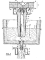
- FIG. 1 which represents a complete continuous casting system, we see at 10 the base of the ladle, lined with its refractory lining 12, at 22 the sinterable insulating refractory and at 23 the seat brick of the fixed nozzle 21 .
- the orifice of the nozzle 21 can be concealed by a sliding shutter, the moving plate of which is seen at 30 and the fixed plate at 35, both pierced with an orifice for the passage of the metal.
- the shutter is in the closed position in FIG. 1.
- the pouring tube 3 which can slide transversely to its axis at the same time as the plate 30 and a removable connection nozzle 19 mounted in leaktight manner thanks to a refractory cement joint between the plate 30 which allows its mounting and the upper part of the tube 3 where it is engaged.
- the nozzle 19 is supported, in the example shown, on an inner hoop 17, metallic and / or refractory formed at the top of the pouring tube 3.
- the tube 3 is located between the ladle 10 and the tundish 13, commonly called “tundish”. This in turn carries a pouring tube 4 - or nozzle - which can also belong to a drawer system and which is located between the distributor 13 and the continuous casting mold 15.
- the invention is applied both to the pouring tubes 3 and 4 and to the connection nozzle 19.
- the tubes 3 and 4 are thus constituted respectively by a thin outer metal casing 1 and 2 whose thickness is of the order of a millimeter.
- the thin metal casing 1 has an annular boss 7 which comes to bear on the sliding support 8.
- the metal envelopes 1 and 2 are lined inside a coating of sinterable insulating material 3a and 4a, acid or basic, the density of which can vary from 0.7 to 2.
- An acid formula can contain:
- the loss on ignition of the material being advantageously less than 6%.
- a basic formula which may be suitable for coating 3 is as follows:
- the loss on ignition being advantageously less than 6%.
- the frame 5 or 6 can preferably be made using a steel sheet about 2 mm thick provided with anchoring means; it may, in particular, include perforations with a diameter of 10 mm, themselves spaced 5 mm apart. It can also be a wire mesh.
- the reinforcement 5 or 6 can also be produced by means of a layer of fibers constituting a nonwoven and / or a tubular layer of mineral and / or organic grains joined together by an organic or mineral binder.
- the reinforcement considered can also be made by means of a fabric of fibers, for example mineral fibers. In all cases, the reinforcement must be mechanically resistant with respect to the material of the coating of the tube within which it is incorporated.
- the thickness of the armature is advantageously between 0.3 and 15 mm depending on the thickness of the coating 3a or 4a of the pouring tube.
- the height of the reinforcements 5 and 6 is such that it reaches - or preferably exceeds - the upper level of the cast metal coming into contact with the outside of the tube.
- the removable interior nozzle 19 of the pouring tube 3 is also produced in accordance with the present invention and comprises (FIG. 3) an internal reinforcement frame 31 similar to the frames 5 and 6 and which extends over the entire height of this nozzle.
- the nozzle 19 is thus composed of a solid and / or perforated metal envelope 20 lined internally with sinterable refractory insulating material 19a similar to the coatings 3a and 4a and in which the frame 31 is embedded.
- the distributor 13 is shown with liquid metal 14 filling it up to level NN1.
- the continuous casting ingot mold 15 is shown with its metal ingot 16 being solidified.
- the mode of action of the means provided for the invention is the following (see FIG. 2).
- the tubular region 26 of the coating 3a located behind the thin outer metallic envelope 1 can only sinter when the corresponding part of this metallic envelope 1 has approximately melted.
- the inner face 24 of the pouring tube which is substantially in contact with the metal jet, gradually sintered during the sequential casting (s) until the sintering reaches the sintered part 26.
- This progressive sintering of the mass of the coating 3a is only possible thanks to the internal frame 5 which, while strengthening the plunging part of the tube, allows it to undergo this transformation without risk of rupture.
- Figure 1 shows the pouring tubes 3 and 4 just before the lower part of their metal casing 1 and 2 has melted.
- the sintering process does not generally reach a sufficient degree of progress at this time so that the plunging end of the tube, assumed to be homogeneous, can withstand the effect of internal pressure and turbulence of liquid steel, which occur at this location.
- the reinforcing reinforcements such as 5, 6 or 31, embedded in the sinterable material, provide the necessary relay to allow the completion without breaking of the sintering process.
- the cutting of the plunging end of the tube which normally occurred along the line lb is then eliminated, which avoids any contact of the metal with the ambient air.
- the reinforcement provided by the invention while remaining coaxial with the pouring tube, must be adapted to the shape of the latter.
Landscapes
- Engineering & Computer Science (AREA)
- Mechanical Engineering (AREA)
- Casting Support Devices, Ladles, And Melt Control Thereby (AREA)
- Refinement Of Pig-Iron, Manufacture Of Cast Iron, And Steel Manufacture Other Than In Revolving Furnaces (AREA)
- Manufacture Of Alloys Or Alloy Compounds (AREA)
- Treatment Of Steel In Its Molten State (AREA)
- Furnace Charging Or Discharging (AREA)
- Continuous Casting (AREA)
- Compositions Of Oxide Ceramics (AREA)
- Ceramic Products (AREA)
Priority Applications (1)
| Application Number | Priority Date | Filing Date | Title |
|---|---|---|---|
| AT83401659T ATE22826T1 (de) | 1982-08-23 | 1983-08-12 | Rohre fuer das giessen von schmelzfluessigem metall. |
Applications Claiming Priority (2)
| Application Number | Priority Date | Filing Date | Title |
|---|---|---|---|
| CH4992/82A CH650176A5 (fr) | 1982-08-23 | 1982-08-23 | Dispositif pour la coulee du metal fondu. |
| CH4992/82 | 1982-08-23 |
Publications (3)
| Publication Number | Publication Date |
|---|---|
| EP0102292A2 true EP0102292A2 (de) | 1984-03-07 |
| EP0102292A3 EP0102292A3 (en) | 1984-07-11 |
| EP0102292B1 EP0102292B1 (de) | 1986-10-15 |
Family
ID=4286064
Family Applications (1)
| Application Number | Title | Priority Date | Filing Date |
|---|---|---|---|
| EP83401659A Expired EP0102292B1 (de) | 1982-08-23 | 1983-08-12 | Rohre für das Giessen von schmelzflüssigem Metall |
Country Status (6)
| Country | Link |
|---|---|
| US (1) | US4792070A (de) |
| EP (1) | EP0102292B1 (de) |
| AT (1) | ATE22826T1 (de) |
| AU (1) | AU569254B2 (de) |
| CH (1) | CH650176A5 (de) |
| DE (2) | DE3366855D1 (de) |
Cited By (4)
| Publication number | Priority date | Publication date | Assignee | Title |
|---|---|---|---|---|
| EP0178053A1 (de) * | 1984-09-06 | 1986-04-16 | Foseco Trading A.G. | Giessrohre |
| FR2617157A1 (fr) * | 1987-06-26 | 1988-12-30 | Vesuvius Crucible Co | Revetement isolant pour corps refractaires, procede de revetement et article associes |
| EP0636441A1 (de) * | 1993-07-26 | 1995-02-01 | Magneco/Metrel, Inc. | Montageblock für eine Ausgussdüse eines Zwischenbehälters |
| US5645120A (en) * | 1992-09-02 | 1997-07-08 | Krosaki Corporation | Joint structure for casting nozzle |
Families Citing this family (7)
| Publication number | Priority date | Publication date | Assignee | Title |
|---|---|---|---|---|
| US4951852A (en) * | 1988-06-23 | 1990-08-28 | Gilbert Rancoulle | Insulative coating for refractory bodies |
| JPH06134557A (ja) * | 1992-10-23 | 1994-05-17 | Tokyo Yogyo Co Ltd | 溶融金属収容容器用スライディングノズル |
| GB9222453D0 (en) * | 1992-10-26 | 1992-12-09 | Shaw Richard D | Improved device for use in continuous casting |
| DE102004057381A1 (de) * | 2004-11-26 | 2006-06-01 | Heraeus Electro-Nite International N.V. | Verfahren zur Regelung des Durchflusses sowie Bodenausguss für ein metallurgisches Gefäß |
| AU2007249057B2 (en) * | 2004-11-26 | 2010-08-12 | Rhi Ag | Regulation method for throughflow and bottom nozzle of a metallurgical vessel |
| JP5116852B2 (ja) * | 2010-03-30 | 2013-01-09 | 明智セラミックス株式会社 | 鋳造ノズル |
| JP6829930B2 (ja) | 2016-08-09 | 2021-02-17 | エーケー スティール プロパティ−ズ、インク. | タンディッシュ漏斗 |
Family Cites Families (23)
| Publication number | Priority date | Publication date | Assignee | Title |
|---|---|---|---|---|
| US1997988A (en) * | 1932-08-27 | 1935-04-16 | Ajax Electrothermic Corp | Furnace lining protection |
| GB583050A (en) * | 1944-05-02 | 1946-12-05 | Brassert & Co | Improvements relating to bessemer converters |
| US2711954A (en) * | 1950-02-23 | 1955-06-28 | Illinois Clay Products Co | Method of reducing sulphur in molten iron and steel |
| US3192582A (en) * | 1962-10-03 | 1965-07-06 | Harbison Walker Refractories | Bottom pour ladle nozzle and stopper rod construction |
| US3229970A (en) * | 1964-03-02 | 1966-01-18 | Harbison Walker Refractories | Metallurgical furnace lining |
| US3934640A (en) * | 1969-09-16 | 1976-01-27 | Concast Ag | Submerged nozzle for continuous casting |
| DE2423358A1 (de) * | 1974-05-14 | 1975-11-20 | Masamitsu Miki | Verfahren zur auskleidung von giesspfannen |
| LU72865A1 (de) * | 1975-06-30 | 1977-03-07 | ||
| FR2333599A1 (fr) * | 1975-12-02 | 1977-07-01 | Daussan Henri | Dispositif a element tubulaire pour la coulee des metaux fondus |
| DE2646707C3 (de) * | 1976-10-13 | 1984-01-26 | Mannesmann AG, 4000 Düsseldorf | Tauchausguß aus feuerfestem Werkstoff für das Stranggießen von Stahl |
| JPS591229B2 (ja) * | 1978-04-26 | 1984-01-11 | 明知耐火煉瓦株式会社 | 溶鋼の連続鋳造用浸漬ノズル |
| FR2433995A1 (fr) * | 1978-08-24 | 1980-03-21 | Daussan & Co | Procede et dispositif pour deboucher l'orifice de coulee d'un recipient metallurgique |
| US4257473A (en) * | 1978-10-02 | 1981-03-24 | Inland Steel Company | Continuous casting shroud apparatus and method |
| DE2919880C2 (de) * | 1979-05-17 | 1983-10-13 | Didier-Werke Ag, 6200 Wiesbaden | Feuerfestes Gießrohr zwischen Gießpfanne und Zwischenbehältern von Stranggießanlagen |
| FR2451789A1 (fr) * | 1979-03-22 | 1980-10-17 | Daussan & Co | Revetement thermiquement isolant pour recipients metallurgiques et procede s'y rapportant |
| BE881486A (fr) * | 1980-01-31 | 1980-07-31 | Hainaut Sambst | Perfectionnement aux dispositifs de coulee d'acier liquide |
| JPS5727967A (en) * | 1980-07-18 | 1982-02-15 | Nippon Steel Corp | Dipping nozzle for continuous casting |
| JPS5738380A (en) * | 1980-08-20 | 1982-03-03 | Kamogawa Kogyo Kk | Tundish lining material for continuous casting |
| FR2493316A1 (fr) * | 1980-11-06 | 1982-05-07 | Science Union & Cie | Nouveau procede de preparation des (trialcoxy benzyl)-1 piperazines et notamment de la (trimethoxy-2', 3', 4' benzyl)-1 piperazine |
| US4423833A (en) * | 1981-01-16 | 1984-01-03 | Didier-Werke A.G. | Refractory immersion spout |
| FR2506641A1 (fr) * | 1981-05-27 | 1982-12-03 | Daussan & Co | Tube de coulee et son procede de fabrication |
| US4568007A (en) * | 1984-01-23 | 1986-02-04 | Vesuvius Crucible Company | Refractory shroud for continuous casting |
| JP2002001566A (ja) * | 2000-06-16 | 2002-01-08 | Matsushita Electric Ind Co Ltd | レーザ加工装置及びレーザ加工方法 |
-
1982
- 1982-08-23 CH CH4992/82A patent/CH650176A5/fr not_active IP Right Cessation
-
1983
- 1983-08-12 DE DE8383401659T patent/DE3366855D1/de not_active Expired
- 1983-08-12 AT AT83401659T patent/ATE22826T1/de not_active IP Right Cessation
- 1983-08-12 EP EP83401659A patent/EP0102292B1/de not_active Expired
- 1983-08-12 DE DE198383401659T patent/DE102292T1/de active Pending
- 1983-08-18 AU AU18111/83A patent/AU569254B2/en not_active Ceased
-
1987
- 1987-08-14 US US07/085,184 patent/US4792070A/en not_active Expired - Fee Related
Cited By (5)
| Publication number | Priority date | Publication date | Assignee | Title |
|---|---|---|---|---|
| EP0178053A1 (de) * | 1984-09-06 | 1986-04-16 | Foseco Trading A.G. | Giessrohre |
| FR2617157A1 (fr) * | 1987-06-26 | 1988-12-30 | Vesuvius Crucible Co | Revetement isolant pour corps refractaires, procede de revetement et article associes |
| EP0296981A3 (en) * | 1987-06-26 | 1990-05-02 | Vesuvius Crucible Company | Insulating coating for refractories, coating process, and associated articles |
| US5645120A (en) * | 1992-09-02 | 1997-07-08 | Krosaki Corporation | Joint structure for casting nozzle |
| EP0636441A1 (de) * | 1993-07-26 | 1995-02-01 | Magneco/Metrel, Inc. | Montageblock für eine Ausgussdüse eines Zwischenbehälters |
Also Published As
| Publication number | Publication date |
|---|---|
| US4792070A (en) | 1988-12-20 |
| DE102292T1 (de) | 1984-07-19 |
| CH650176A5 (fr) | 1985-07-15 |
| EP0102292A3 (en) | 1984-07-11 |
| EP0102292B1 (de) | 1986-10-15 |
| AU569254B2 (en) | 1988-01-28 |
| ATE22826T1 (de) | 1986-11-15 |
| AU1811183A (en) | 1984-03-01 |
| DE3366855D1 (en) | 1986-11-20 |
Similar Documents
| Publication | Publication Date | Title |
|---|---|---|
| EP0102292B1 (de) | Rohre für das Giessen von schmelzflüssigem Metall | |
| EP0048641B2 (de) | Vorrichtung zum Schützen geschmolzenen Metalls in Schieberverschlüssen | |
| FR2582553A1 (fr) | Dispositif et procede de coulee de metal | |
| FR2516415A1 (fr) | Dispositif pour eliminer les inclusions contenues dans les metaux liquides | |
| EP0305426B1 (de) | Verfahren und vorrichtung zum giessen von flüssigem metall | |
| EP0508246A1 (de) | Stopfenstange mit verschliessfester Hülse | |
| EP0065514B1 (de) | Thermisch isolierendes giessrohr für metallurgisches gefäss | |
| EP0589762B1 (de) | Giessrohr für Metall und Verfahren zu seiner Herstellung | |
| CA1094775A (fr) | Embout de raccordement de la tuyauterie d'une pompe electromagnetique et ses applications | |
| EP0907439B1 (de) | Vertikal-stranggiesskokille mit aufsatz | |
| BE1004282A6 (fr) | Dispositif de prechauffage d'une busette de coulee d'un metal en fusion et installation de coulee d'un metal equipee de ce dispositif. | |
| EP0836539B1 (de) | Kombination platte-innere ausgussdüse mit einer sollbruchstelle | |
| FR2659880A1 (fr) | Dispositif de liaison entre un recipient metallurgique contenant un metal liquide et une lingotiere. | |
| FR2635283A1 (fr) | Joint de tube protecteur pour la coulee de metaux en fusion | |
| FR2541915A2 (fr) | Dispositif d'amenee du metal dans les lingotieres de coulee continue | |
| EP0387229A1 (de) | Prallplatte für eine Giesspfanne | |
| EP1348505A1 (de) | Wärmeschockbeständiges Ausgiessformteil und Verfahren zu seiner Herstellung | |
| EP0990474B1 (de) | Inertgasabschirmvorrichtung für Kokillen zum Stranggiessen von Metall | |
| FR2643001A1 (fr) | Organe de coulee comportant une surface plane de glissement pour une plaque tiroir associee | |
| BE1015358A3 (fr) | Procede et dispositif pour la coulee continue en charge d'un metal en fusion. | |
| EP0804307A1 (de) | Verfahren und vorrichtung zum giessen eines metalls in eine form | |
| FR2845196A1 (fr) | Conteneur pour matieres radioactives et procede de fermeture d'un tel conteneur | |
| FR2553317A1 (fr) | Joint pour installation de coulee continue horizontale des metaux notamment de l'acier et installation de coulee equipee de ce joint | |
| FR2766394A1 (fr) | Reglage de la tete d'une lingotiere de coulee continue en charge des metaux | |
| FR2684577A1 (fr) | Tube de coulee a manchon refractaire. |
Legal Events
| Date | Code | Title | Description |
|---|---|---|---|
| PUAI | Public reference made under article 153(3) epc to a published international application that has entered the european phase |
Free format text: ORIGINAL CODE: 0009012 |
|
| 17P | Request for examination filed |
Effective date: 19830816 |
|
| AK | Designated contracting states |
Designated state(s): AT DE FR IT |
|
| ITCL | It: translation for ep claims filed |
Representative=s name: BARZANO' E ZANARDO ROMA S.P.A. |
|
| TCAT | At: translation of patent claims filed | ||
| PUAL | Search report despatched |
Free format text: ORIGINAL CODE: 0009013 |
|
| AK | Designated contracting states |
Designated state(s): AT DE FR IT |
|
| DET | De: translation of patent claims | ||
| ITF | It: translation for a ep patent filed | ||
| GRAA | (expected) grant |
Free format text: ORIGINAL CODE: 0009210 |
|
| AK | Designated contracting states |
Kind code of ref document: B1 Designated state(s): AT DE FR IT |
|
| REF | Corresponds to: |
Ref document number: 22826 Country of ref document: AT Date of ref document: 19861115 Kind code of ref document: T |
|
| REF | Corresponds to: |
Ref document number: 3366855 Country of ref document: DE Date of ref document: 19861120 |
|
| PLBI | Opposition filed |
Free format text: ORIGINAL CODE: 0009260 |
|
| 26 | Opposition filed |
Opponent name: DIDIER-WERKE AG Effective date: 19870709 |
|
| PLBN | Opposition rejected |
Free format text: ORIGINAL CODE: 0009273 |
|
| STAA | Information on the status of an ep patent application or granted ep patent |
Free format text: STATUS: OPPOSITION REJECTED |
|
| 27O | Opposition rejected |
Effective date: 19890818 |
|
| ITTA | It: last paid annual fee | ||
| PGFP | Annual fee paid to national office [announced via postgrant information from national office to epo] |
Ref country code: AT Payment date: 19990806 Year of fee payment: 17 |
|
| PG25 | Lapsed in a contracting state [announced via postgrant information from national office to epo] |
Ref country code: AT Free format text: LAPSE BECAUSE OF NON-PAYMENT OF DUE FEES Effective date: 20000812 |
|
| PGFP | Annual fee paid to national office [announced via postgrant information from national office to epo] |
Ref country code: FR Payment date: 20030227 Year of fee payment: 20 |
|
| PGFP | Annual fee paid to national office [announced via postgrant information from national office to epo] |
Ref country code: DE Payment date: 20030228 Year of fee payment: 20 |