EP0102267B1 - Gerät zum Ablegen eines landwirtschaftlichen Stoffes in die Erde - Google Patents
Gerät zum Ablegen eines landwirtschaftlichen Stoffes in die Erde Download PDFInfo
- Publication number
- EP0102267B1 EP0102267B1 EP83401503A EP83401503A EP0102267B1 EP 0102267 B1 EP0102267 B1 EP 0102267B1 EP 83401503 A EP83401503 A EP 83401503A EP 83401503 A EP83401503 A EP 83401503A EP 0102267 B1 EP0102267 B1 EP 0102267B1
- Authority
- EP
- European Patent Office
- Prior art keywords
- furrow
- implement
- conduit
- soil
- aperture
- Prior art date
- Legal status (The legal status is an assumption and is not a legal conclusion. Google has not performed a legal analysis and makes no representation as to the accuracy of the status listed.)
- Expired
Links
- 239000002689 soil Substances 0.000 title claims abstract description 35
- 239000012773 agricultural material Substances 0.000 title claims abstract description 12
- 238000000151 deposition Methods 0.000 title claims abstract description 12
- 239000000463 material Substances 0.000 claims abstract description 54
- 238000000034 method Methods 0.000 claims abstract description 15
- 239000003337 fertilizer Substances 0.000 description 4
- 235000008733 Citrus aurantifolia Nutrition 0.000 description 3
- 235000011941 Tilia x europaea Nutrition 0.000 description 3
- 239000004571 lime Substances 0.000 description 3
- 239000004576 sand Substances 0.000 description 3
- XLYOFNOQVPJJNP-UHFFFAOYSA-N water Substances O XLYOFNOQVPJJNP-UHFFFAOYSA-N 0.000 description 2
- 239000004411 aluminium Substances 0.000 description 1
- 229910052782 aluminium Inorganic materials 0.000 description 1
- XAGFODPZIPBFFR-UHFFFAOYSA-N aluminium Chemical compound [Al] XAGFODPZIPBFFR-UHFFFAOYSA-N 0.000 description 1
- 150000001399 aluminium compounds Chemical class 0.000 description 1
- 229940077746 antacid containing aluminium compound Drugs 0.000 description 1
- 230000008878 coupling Effects 0.000 description 1
- 238000010168 coupling process Methods 0.000 description 1
- 238000005859 coupling reaction Methods 0.000 description 1
- 230000008021 deposition Effects 0.000 description 1
- -1 for example Substances 0.000 description 1
- 230000005484 gravity Effects 0.000 description 1
- 238000007689 inspection Methods 0.000 description 1
- 239000007788 liquid Substances 0.000 description 1
- 229910052751 metal Inorganic materials 0.000 description 1
- 239000002184 metal Substances 0.000 description 1
- 239000002245 particle Substances 0.000 description 1
- 230000007096 poisonous effect Effects 0.000 description 1
- 239000007787 solid Substances 0.000 description 1
Images

Classifications
-
- A—HUMAN NECESSITIES
- A01—AGRICULTURE; FORESTRY; ANIMAL HUSBANDRY; HUNTING; TRAPPING; FISHING
- A01C—PLANTING; SOWING; FERTILISING
- A01C21/00—Methods of fertilising, sowing or planting
- A01C21/002—Apparatus for sowing fertiliser; Fertiliser drill
Definitions
- This invention relates to an agricultural method and implement. More particularly the invention relates to a method and implement for depositing an agricultural material such as, for example, fertilizers, agricultural lime, etc., deep into the soil in which a particular crop is to be planted.
- an agricultural material such as, for example, fertilizers, agricultural lime, etc.
- the material being deposited is relatively light such, as for example, when it comprises agricultural lime or the like.
- the conduit may be so located in the furrow that the aperture is at the required depth at which the material has to be deposited in the furrow.
- the material may be deposited as a wide band extending over a substantial part of the furrow in the vertical direction.
- the method includes the steps of drawing a furrow in the soil by means of a ripper tine orthe like, and passing the material depositing conduit into the furrow immediately behind the tine.
- the method includes the step of causing soil in the immediate vicinity of the furrow to pass into the furrow to cover the material as soon as the latter has been deposited in thefurrow.
- an implement for depositing an agricultural material in soil below ground surface by means of an elongate downwardly-extending conduit adapted to pass into a furrow or the like drawn into the soil, the conduit having at least one aperture at the rear side thereof towards its lower end; and a mechanically operated conveyor for forcing such material to pass down the conduit and out through the or each aperture into the furrow by falling onto a transversely extending platform located belowthe at least one aperture and be scattered in the transverse direction in the furrow.
- the conduit includes a plurality of apertures and platforms spaced axially over its length.
- the apertures are arranged in two parallel extending rows, the apertures in each row increasing in size from the top aperture towards the bottom aperture.
- the means for forcing the material down the conduit comprises an elongated worm gear which is rotatably contained in the bore of the conduit.
- the worm gear may be driven in any suitable manner.
- the worm gear is driven through the rotation of a land engageable wheel associated with the implement.
- Such rotation may, for example, be effected through a chain extending between a sprocket on such a wheel and a sprocket mounted on a shaft which is rotatably connected to the worm gear.
- the land engageable wheel may be biased towards continuous engagement with the ground surface.
- Such biasing means may, for example, comprise a suitable spring or the like extending between the wheel, or its mounting, and the implement.
- the conduit's material conveying means comprises a device adapted to cause a vibration in the conduit sufficient to cause the material to pass down the conduit.
- the implement may include a container in which the material to be fed into the furrow is held, and into which the upper end of the conduit passes.
- the implement includes a ripper tine adapted to draw a furrow in the soil, the said conduit being mounted in close trailing relationship relative to the tine with the lower end of the conduit being located at substantially the same level as the lower end of the tine.
- the material may be deposited in the furrow immediately behind the tine and hence before any significant amount of soil from the furrow surroundings can start to fall into the furrow.
- the lower end of the worm gear extends a small distance beyond the lower end of the conduit.
- the implement includes a furrow closing member which is mounted on the implement in trailing relationship to the conduit.
- the furrow closing member preferably includes an elongated element adapted to pass into the furrow and one or more projections extending transversely the element which are adapted to rake soil from the sides of the furrow into the furrow as the element moves along the furrow.
- the implement may also include a compacting wheel in trailing relationship to the furrow closing member, the wheel being adapted to press the soil, which has been racked back into the furrow by the said member, firmly down into the furrow.
- the implement includes a frame on which the various aforesaid components are mounted and which can be drawn by a tractor or the like.
- the frame is adapted to be coupled to the three point hitching mechanism of a tractor or the like.
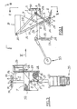
- the implement includes a metal frame which is defined by a horizontally extending beam 1 of which the one end is connected to a ripper tine 2 by means of a vertically extending beam 3.
- the other end of beam 1 is connected to a horizontally extending beam 4 and a pair of vertically extending interconnected beams 5 are mounted on its centre.
- the material intended to be deposited in the soil by the implement is introduced to container 7 through the open end 10 thereof.
- Conduit 9 of which the lower end extends to substantially the same level as the tip of tine 2, is connected by means of a substantially triangularly shaped plate 11 to the rear end of beam 3.
- Plate 11 is also connected to a horizontally extending elongated beam 12 which, in turn, has its one end connected to beam 1.
- the other end of beam 12 is connected to a vertically extending elongated member 13 which includes a scoop 14 towards its lower end and which is provided over its length with a plurality of transversely extending raking elements 15.
- Member 13 is located substantially in linear trailing relationship relative to beam 3.
- An elongated worm gear 16 is rotatably received in the bore of conduit 9.
- the lower end of worm gear 16 extends a short distance beyond the lower end of conduit 9 while the upper end of worm gear 16 extends a substantial distance into the interior of container 7.
- Worm gear 16 includes towards its upper end a bevelled gear 17 which merges with another bevelled gear 18 which is carried on a shaft 19 which is rotatably received in a bearing 20 mounted on the side wall of container 7.
- a sprocket 21 which is connected to the free end of shaft 19 is rotatably linked by means of a chain 22 to a sprocket 23 which is carried on the shaft 25 on which a land engageable wheel 24 is mounted.
- Shaft 25 is rotatably received between the two ends of arms 26 of which the other ends are secured to the main frame of the implement.
- Wheel 24 is so mounted that it runs on one side of the implement.
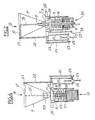
- Conduit 9 is provided along its rear end with two parallel spaced rows of apertures 27 which increase in size from the top apertures towards the bottom apertures.
- Each aperture 27 is associated with a transversely extending projection 28 which is located immediately below the aperture and which defines a platform onto which material passing from inside conduit 9 via an aperture 27 can fall.
- Beam 4 is provided at each of its opposite ends with a pin 29 which, together with a pair of aligned apertures 30 in the upper end of beams 5, serves as the connecting means for coupling the implement to the three-point hitching mechanism of a tractor or the like (not shown).
- Studs 31 serve to re-inforce the connection of beams 4 and 5 to one another.
- a wire mesh 32 which is provided over the open end 10 of container 7, ensures that only material smaller than a particular particle size can pass into container 7.
- a lid 33, provided in the rear side wall container 7 allows access to the inside of container of 7 for inspection purposes.
- a pair of removable legs 34 serves to support the implement in the upright position when it is not in use.
- container 7 is filled with the particular material to be deposited in the soil; the implement hitched to the rear end of a tractor or the like: and legs 34 removed.
- the tractor's hitch mechanism When the implement is located in the particular area where the material has to be deposited in the soil, the tractor's hitch mechanism is operated to cause tine 2 and wheel 24 to engage the soil surface. When the implement is then drawn over the surface, tine 2 penetrates the soils to draw a deep groove or furrow into the it. At the same time, because of the rotational engagement between wheel 24 and the ground surface, shaft 19, and hence worm gear 16, is rotated.
- the material is accordingly deposited in the furrow in a relatively wide band which extends substantially from the upper end of the furrow vertically downward to the bottom end of the furrow.
- Trailing member 13 with its scoop 14 and rake elements 15 immediately draws soil located in the immediate vicinity of the furrow into the furrow to cover the deposited material.
- a compacting wheel 35 located in linear trailing relationship to member 13 may be provided for pressing down firmly the raked back soil in the furrow.
- Applicant has found that it is possible with the implement to deposit agricultural material to a depth in the order of 900 mm below ground surface.
- the applicant has furthermore found that a crop raised under severe draught conditions in soil treated with, say, a particular fertilizer by means of the implement according to the invention, was substantially better than a crop raised under similar conditions but with the fertilizer being deposited in the soil in the conventional manner.
- the rate at which a particular material may be deposited in the soil can be changed by varying the speed of rotation of worm gear 16 and/or the sizes of apertures 27.
- a motor may be utilised for this purpose.
- concentration of the deposited material in any particular zone in the furrow may be varied by changing the size of the apertures 27 in conduit 9 in such zone. It will also be appreciated that instead of being a solid, the material deposited may also be in liquid form.
Landscapes
- Life Sciences & Earth Sciences (AREA)
- Soil Sciences (AREA)
- Environmental Sciences (AREA)
- Soil Working Implements (AREA)
- Springs (AREA)
- Soil Conditioners And Soil-Stabilizing Materials (AREA)
- Cultivation Of Plants (AREA)
- Sowing (AREA)
Claims (19)
Priority Applications (1)
| Application Number | Priority Date | Filing Date | Title |
|---|---|---|---|
| AT83401503T ATE32011T1 (de) | 1982-07-21 | 1983-07-21 | Geraet zum ablegen eines landwirtschaftlichen stoffes in die erde. |
Applications Claiming Priority (2)
| Application Number | Priority Date | Filing Date | Title |
|---|---|---|---|
| ZA825205 | 1982-07-21 | ||
| ZA825205 | 1982-07-21 |
Publications (2)
| Publication Number | Publication Date |
|---|---|
| EP0102267A1 EP0102267A1 (de) | 1984-03-07 |
| EP0102267B1 true EP0102267B1 (de) | 1988-01-20 |
Family
ID=25576176
Family Applications (1)
| Application Number | Title | Priority Date | Filing Date |
|---|---|---|---|
| EP83401503A Expired EP0102267B1 (de) | 1982-07-21 | 1983-07-21 | Gerät zum Ablegen eines landwirtschaftlichen Stoffes in die Erde |
Country Status (4)
| Country | Link |
|---|---|
| EP (1) | EP0102267B1 (de) |
| AT (1) | ATE32011T1 (de) |
| AU (1) | AU1713883A (de) |
| DE (1) | DE3375355D1 (de) |
Families Citing this family (3)
| Publication number | Priority date | Publication date | Assignee | Title |
|---|---|---|---|---|
| CN111837544A (zh) * | 2020-06-12 | 2020-10-30 | 宁夏利农工贸有限公司 | 一种硒砂瓜农家肥专用施肥机 |
| CN111937514B (zh) * | 2020-08-12 | 2023-06-02 | 安徽省农业科学院棉花研究所 | 一种早熟棉种植用施肥装置 |
| NL2027670B1 (en) * | 2021-02-26 | 2022-09-20 | Van Merksteijn Real Estate B V | Reducing carbon dioxide levels in the atmosphere |
Family Cites Families (3)
| Publication number | Priority date | Publication date | Assignee | Title |
|---|---|---|---|---|
| FR951823A (fr) * | 1947-08-08 | 1949-11-04 | Charrues Fondeur Soc D | Charrue pour enfouissage profond de produits tels qu'engrais, produits insecticides ou autres |
| FR1205861A (fr) * | 1958-01-23 | 1960-02-05 | Distributeur d'engrais pour sous-soleuse | |
| DE1998708U (de) * | 1968-09-28 | 1968-12-19 | Amazonen Werke Dreyer H | Maschine zum ausbringen von staubfoermigem und gekoerntem material. |
-
1983
- 1983-07-21 DE DE8383401503T patent/DE3375355D1/de not_active Expired
- 1983-07-21 AT AT83401503T patent/ATE32011T1/de not_active IP Right Cessation
- 1983-07-21 EP EP83401503A patent/EP0102267B1/de not_active Expired
- 1983-07-21 AU AU17138/83A patent/AU1713883A/en not_active Abandoned
Also Published As
| Publication number | Publication date |
|---|---|
| EP0102267A1 (de) | 1984-03-07 |
| ATE32011T1 (de) | 1988-02-15 |
| DE3375355D1 (en) | 1988-02-25 |
| AU1713883A (en) | 1984-01-26 |
Similar Documents
| Publication | Publication Date | Title |
|---|---|---|
| JP5577552B2 (ja) | 施肥できる農作業機 | |
| DE3028382C2 (de) | ||
| US4552079A (en) | Machine for planting seeds | |
| EP0102267B1 (de) | Gerät zum Ablegen eines landwirtschaftlichen Stoffes in die Erde | |
| EP0016499A1 (de) | Landwirtschaftliches Gerät und landwirtschaftliche Verfahren | |
| DE2644948C2 (de) | Pflanzmaschine zum Auspflanzen von vorgezogenen Pflanzen | |
| NL8100233A (nl) | Inrichting voor het verbeteren van landbouwgrond en zaaimachine voorzien van deze inrichting. | |
| CA1135125A (en) | Grain drill | |
| US3822656A (en) | Subsoil amendment material incorporating method and apparatus | |
| US2756544A (en) | Method and apparatus for dispensing fertilizers to irrigation water | |
| CN108093711B (zh) | 一种翻土增肥设备 | |
| US3939785A (en) | Sprig planting apparatus | |
| DE2752646A1 (de) | Vorrichtung zum anheben von erdboden ohne wenden | |
| DE2647721C2 (de) | ||
| DE2936145C2 (de) | Vorrichtung zur Entnahme von Bodenproben für die Landwirtschaft | |
| US3513789A (en) | Seed planting mechanism | |
| DE3604954A1 (de) | Verfahren zum ausstreuen von mineralischem streugut mit einem duengerstreuer und zur durchfuehrung des verfahrens geeigneter duengerstreuer | |
| US2760686A (en) | Shaker type fertilizer drill attachments for commercial fertilizer distributors | |
| DE817660C (de) | Kartoffelpflanzmaschine | |
| CN111482450A (zh) | 土壤重金属分层治理方法 | |
| CN120814378B (zh) | 一种多功能农业耕种机 | |
| DE3151581C2 (de) | Vorrichtung zum Austragen von Kalk oder dergl. auf in Reihen eingesäte Rüben oder dergl. | |
| CN110800435A (zh) | 一种果园有机肥料条沟施肥机 | |
| US5003712A (en) | Apparatus for cleaning irrigation ditch | |
| DE2828636A1 (de) | Pulver- oder granulatstreuer |
Legal Events
| Date | Code | Title | Description |
|---|---|---|---|
| PUAI | Public reference made under article 153(3) epc to a published international application that has entered the european phase |
Free format text: ORIGINAL CODE: 0009012 |
|
| AK | Designated contracting states |
Designated state(s): AT BE CH DE FR GB IT LI LU NL SE |
|
| 17P | Request for examination filed |
Effective date: 19840904 |
|
| GRAA | (expected) grant |
Free format text: ORIGINAL CODE: 0009210 |
|
| AK | Designated contracting states |
Kind code of ref document: B1 Designated state(s): AT BE CH DE FR GB IT LI LU NL SE |
|
| PG25 | Lapsed in a contracting state [announced via postgrant information from national office to epo] |
Ref country code: NL Effective date: 19880120 Ref country code: LI Effective date: 19880120 Ref country code: IT Free format text: LAPSE BECAUSE OF FAILURE TO SUBMIT A TRANSLATION OF THE DESCRIPTION OR TO PAY THE FEE WITHIN THE PRESCRIBED TIME-LIMIT;WARNING: LAPSES OF ITALIAN PATENTS WITH EFFECTIVE DATE BEFORE 2007 MAY HAVE OCCURRED AT ANY TIME BEFORE 2007. THE CORRECT EFFECTIVE DATE MAY BE DIFFERENT FROM THE ONE RECORDED. Effective date: 19880120 Ref country code: FR Free format text: THE PATENT HAS BEEN ANNULLED BY A DECISION OF A NATIONAL AUTHORITY Effective date: 19880120 Ref country code: CH Effective date: 19880120 Ref country code: BE Effective date: 19880120 Ref country code: AT Effective date: 19880120 |
|
| REF | Corresponds to: |
Ref document number: 32011 Country of ref document: AT Date of ref document: 19880215 Kind code of ref document: T |
|
| PG25 | Lapsed in a contracting state [announced via postgrant information from national office to epo] |
Ref country code: SE Effective date: 19880131 |
|
| REF | Corresponds to: |
Ref document number: 3375355 Country of ref document: DE Date of ref document: 19880225 |
|
| REG | Reference to a national code |
Ref country code: CH Ref legal event code: PL |
|
| EN | Fr: translation not filed | ||
| NLV1 | Nl: lapsed or annulled due to failure to fulfill the requirements of art. 29p and 29m of the patents act | ||
| PG25 | Lapsed in a contracting state [announced via postgrant information from national office to epo] |
Ref country code: GB Effective date: 19880721 |
|
| PG25 | Lapsed in a contracting state [announced via postgrant information from national office to epo] |
Ref country code: LU Free format text: LAPSE BECAUSE OF NON-PAYMENT OF DUE FEES Effective date: 19880731 |
|
| PLBE | No opposition filed within time limit |
Free format text: ORIGINAL CODE: 0009261 |
|
| STAA | Information on the status of an ep patent application or granted ep patent |
Free format text: STATUS: NO OPPOSITION FILED WITHIN TIME LIMIT |
|
| 26N | No opposition filed | ||
| GBPC | Gb: european patent ceased through non-payment of renewal fee | ||
| PG25 | Lapsed in a contracting state [announced via postgrant information from national office to epo] |
Ref country code: DE Effective date: 19890401 |