EP0101465B1 - Improvements in and relating to colour scanners - Google Patents
Improvements in and relating to colour scanners Download PDFInfo
- Publication number
- EP0101465B1 EP0101465B1 EP83900647A EP83900647A EP0101465B1 EP 0101465 B1 EP0101465 B1 EP 0101465B1 EP 83900647 A EP83900647 A EP 83900647A EP 83900647 A EP83900647 A EP 83900647A EP 0101465 B1 EP0101465 B1 EP 0101465B1
- Authority
- EP
- European Patent Office
- Prior art keywords
- beam splitter
- exit
- light
- scanner
- entrance
- Prior art date
- Legal status (The legal status is an assumption and is not a legal conclusion. Google has not performed a legal analysis and makes no representation as to the accuracy of the status listed.)
- Expired
Links
- 230000003287 optical effect Effects 0.000 claims abstract description 18
- 239000011521 glass Substances 0.000 claims description 3
- 239000000463 material Substances 0.000 claims description 3
- 239000012780 transparent material Substances 0.000 claims 1
- 230000007547 defect Effects 0.000 abstract description 2
- 238000000149 argon plasma sintering Methods 0.000 abstract 1
- 239000000428 dust Substances 0.000 abstract 1
- 239000011248 coating agent Substances 0.000 description 3
- 238000000576 coating method Methods 0.000 description 3
- 101100117236 Drosophila melanogaster speck gene Proteins 0.000 description 2
- 244000283070 Abies balsamea Species 0.000 description 1
- 235000007173 Abies balsamea Nutrition 0.000 description 1
- 239000004858 Canada balsam Substances 0.000 description 1
- 239000000853 adhesive Substances 0.000 description 1
- 230000001070 adhesive effect Effects 0.000 description 1
- 150000001875 compounds Chemical class 0.000 description 1
- 230000000694 effects Effects 0.000 description 1
- 238000003384 imaging method Methods 0.000 description 1
- 238000000034 method Methods 0.000 description 1
Images

Classifications
-
- H—ELECTRICITY
- H04—ELECTRIC COMMUNICATION TECHNIQUE
- H04N—PICTORIAL COMMUNICATION, e.g. TELEVISION
- H04N1/00—Scanning, transmission or reproduction of documents or the like, e.g. facsimile transmission; Details thereof
- H04N1/46—Colour picture communication systems
- H04N1/48—Picture signal generators
- H04N1/486—Picture signal generators with separate detectors, each detector being used for one specific colour component
- H04N1/488—Picture signal generators with separate detectors, each detector being used for one specific colour component using beam-splitters
-
- H—ELECTRICITY
- H04—ELECTRIC COMMUNICATION TECHNIQUE
- H04N—PICTORIAL COMMUNICATION, e.g. TELEVISION
- H04N9/00—Details of colour television systems
- H04N9/11—Scanning of colour motion picture films, e.g. for telecine
Definitions
- This invention concerns scanners of the kind where an original information bearing record such as a photographic negative or positive is scanned in a point to point manner by a spot of light and the spot of light is modulated by the information carried by, the record.
- the modulated spot of light is passedto a photomultiplier or like photosensitive device and an electrical signal is generated which corresponds to the instantaneous information carried by the original at that point.
- Such so apparatus may form part of a telecine apparatus, a photographic printer, a facsimile transmitter or a document copier.
- One method of scanning in a point to point manner is to utilise a cathode ray tube and to provide a raster on the face thereof.
- the raster is imaged on the original information bearing record and the transmitted modulated light, if the original is transparent such as a photographic negative or positive, is detected. It is known, however, to utilise a point liht source and appropriate optical components to obtain point to point scanning.
- a colour scanner comprising a gate whereat a transparency to be scanned may be located, means for scanning the transparency in a point to point manner with a spot of light, a beam splitter located so as to receive light transmitted by the transparency, and a photomultiplier or like photoresponsive device located proximate each exit of the beam splitter, characterised in that, between the gate and the entrance to the beam splitter, the optical path is defined by internally reflective means.
- the optical path defining means may comprise internally reflective mirror boxes and/or lenses for containing and directing modulated light from the transparency or other information bearing record to the entrance of the beam splitter. There may be similar optical path defining means from the exits of the beam splitter to the detecting surfaces of the photomultipliers or like photoresponsive devices.
- the beam splitter is preferably of cubic form and of a material of high refractive index such as glass.
- a colour film scanner 10 is arranged to scan a colour transparency 11 (positive or negative) and to provide point to point image infoformaticn as to the colour content and density of the transparency, in the form of electrical signals at the outputs of three photomultipliers 12, 13 and 14.
- the scanner comprises a cathode ray tube 15, the electrical circuits of which provide horizontal and vertical time bases to produce a raster on the face 16 thereof of relative dimensions at least corresponding to the dimensions of the transparency 11 to be scanned.
- An objective 17 images the raster onto the transparency 11 located in a film gate 18.
- Light transmitted by the transparency is collected by optical path defining means comprising a first truncated pyramidal mirror box 30 surrounding the gate 18, and lenses 19 and 20 direct the collected light onto the plsnar entrance face 40 of a transparent beam splitting cube 21 forming a further part of the optical path defining means.
- the cube 21 comprises two equal right angled prisms 41 and 42 of a relatively high refractive index material such as glass.
- the hypoteneusal surface of one of the prisms 41 or 42 has a dichroic mirror formed as an interference coating thereon of thickness such as to reflect red light incident thereon at approximately 45° and to transmit green and blue light incident thereon at approximately 45°.
- the prisms 41 and 42 are cemented together with Canada balsam or a like adhesive with the hypoteneusal surfaces in contact along the line 22.
- the cube 21 has a first planar exit face 43 parallel to the entrance face wherethrough green and blue light transmitted by the dichroic mirror exit the cube, and a second planar exit face 44 at right angles to the entrance face 40 wherethrough red light reflected by the dichroic mirror exits the cube.
- the second exit face is surrounded by a rectangular box mirror 31 having internal reflecting surfaces which box mirror contains and directs light exiting the cube at the face 44.
- a lens 23 followed by a truncated ramidal mirror box 52 directs such light onto the photocathode 24 of the photomultiplier 12.
- Abutting the first exit face 43 of the cube 21 is a second similar cube 28 such that the first exit face 43 constitutes also an entrance face for the cube 28.
- a similarly formed dichroic mirror 29 transmits green light, entering the cube 28 and impinging on the mirror 29 at approximately 45°, to a first exit face 45 of the second cube 28 and a similar optical arrangement comprising a mirror box 31 b, a lens 23b and a truncated pyramidal box 32b collects light exiting the exit face 45 and directs it to the photocathode 24b of the photomultiplier 14.
- the dichroic mirror 29 reflects blue light, impinging thereon at approximately 45°, to a second exit face 48 whereat a corresponding optical arrangement comprising a rectangular mirror box 31a, a lens 23a and a truncated pyramidal mirror box 32a collects and directs the reflected light to the photocathode 24a of the photomultiplier 13.
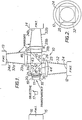
- the lenses 19 and 20 and 23, 23a or 23b serve to image the aperture of the objective 17 as a circle 25 (or as a polygon if the aperture is formed as an iris diaphragm) (See Fig. 2) on the respective photocathode instead of imaging the transparency 11.
- the transparency is deliberately totally defocussed on the photocathode. In this way, a constant area, the circle 25, of fixed location, on the photocathode is illuminated irrespective of the instantaneous location of the spot of light on the transparency 11 and any inequalities of response existing on the detecting surfaces, the photocathodes 24, 24a and 24b, are eliminated.
- the light from the cathode ray tube passes therethrough specularly and enters the cubes 21 and 28 such as to strike the dichroic mirrors 22 and 29 at an optimum angle of approximately 45°, the design angle of the coating thickness of the interference coating. If there are specks of dirt or scratches on the transparency 11, then light is scattered and/or absorbed thereby.
- the mirror box 30 collects most of the scattered light and the lenses 19, 20 direct the light such that most of it strikes the entrance face 40 of the cube 21. Any light which enters the cube 21 can only exit therefrom at the exit faces 43 and 44 or 45 and 46. However, scattered light entering the entrance face 40 impinges on the mirror 22 at any angle between 0° and 90° and only a proportion of such light will be in the region of the optimum design angle of 45'
- the dichroic mirror 22 may transmit some scattered red light and reflect some scattered blue and green light.
- the mirror 29 will transmit some scattered blue light and will reflect some green and red light.
- substantially all of the scattered light entering the entrance face 40 will reach the photomultipliers 12, 13 and 14 and the summed level of the output signals will be such as nearly to equate in value to the average value of the specular signal of the surrounding area of the transparency 11 although the reproduction from such signals will not be of the correct colour.
- the human eye is much more sensitive to changes in density than to changes in colour in the fine detail of a reproduction and consequently the detectable effects in a reproduction, of scratches and dirt on the transparency 11, are minimised or eliminated.
- the mirror boxes 31 and 52, 31a and 32a or 31 b and 32b may be all of the form of the mirror box 30 where the lenses are contained within the boxes.
- the mirror boxes may be two stage truncated pyramids, the stages 47 and 48 having different included angles.
- Fig. 4 shows a scanner having mirror boxes 49 and 50, 50a and 50b in the form of compound parabalic concentrators which tend to direct light entering at the narrow end over a hemisphere of 180° into a cone of light which would enter the entrance face of the cube 21 at approximately 90° thereto.
- similar reference numerals have been used for like parts.
- the cube 21, in order to minimise light losses must have a square cross-section in a plane at right angles to its entrance and exit faces. However, in a plane parallel to the entrance face, the beam splitter may have a rectangular cross-section commensurate with or corresponding to the dimensions of the transparency 11 and the gate 18.
Landscapes
- Engineering & Computer Science (AREA)
- Multimedia (AREA)
- Signal Processing (AREA)
- Facsimile Scanning Arrangements (AREA)
- Optical Elements Other Than Lenses (AREA)
Applications Claiming Priority (2)
| Application Number | Priority Date | Filing Date | Title |
|---|---|---|---|
| GB8204083 | 1982-02-12 | ||
| GB8204083 | 1982-02-12 |
Publications (2)
| Publication Number | Publication Date |
|---|---|
| EP0101465A1 EP0101465A1 (en) | 1984-02-29 |
| EP0101465B1 true EP0101465B1 (en) | 1986-02-05 |
Family
ID=10528280
Family Applications (1)
| Application Number | Title | Priority Date | Filing Date |
|---|---|---|---|
| EP83900647A Expired EP0101465B1 (en) | 1982-02-12 | 1983-02-09 | Improvements in and relating to colour scanners |
Country Status (7)
| Country | Link |
|---|---|
| US (1) | US4586076A (it) |
| EP (1) | EP0101465B1 (it) |
| JP (1) | JPH0669220B2 (it) |
| CA (1) | CA1211053A (it) |
| DE (1) | DE3362046D1 (it) |
| IT (1) | IT1161886B (it) |
| WO (1) | WO1983002869A1 (it) |
Families Citing this family (7)
| Publication number | Priority date | Publication date | Assignee | Title |
|---|---|---|---|---|
| US4809062A (en) * | 1984-11-14 | 1989-02-28 | Microtek Lab., Inc. | Optical color line scanning and imaging device having a roller drive |
| US5604607A (en) * | 1992-10-19 | 1997-02-18 | Eastman Kodak Company | Light concentrator system |
| JPH08510333A (ja) * | 1993-03-31 | 1996-10-29 | ヒューズ − ジェイブイシー テクノロジー コーポレイション | 単一投影レンズのカラー投影システム |
| GB9705473D0 (en) * | 1997-03-17 | 1997-05-07 | Innovation Tk Limited | Telecine systems |
| GB2343077A (en) * | 1998-08-21 | 2000-04-26 | Cintel Int Ltd | Film scanner using a diffuser to reduce visibility of imperfections on film surface |
| GB9818443D0 (en) * | 1998-08-24 | 1998-10-21 | Innovation Tk Limited | Colour scanner |
| US7177050B2 (en) | 2000-12-20 | 2007-02-13 | Cintel International Limited | System for reducing scratch visibility |
Family Cites Families (12)
| Publication number | Priority date | Publication date | Assignee | Title |
|---|---|---|---|---|
| US1781800A (en) * | 1928-04-16 | 1930-11-18 | Baird Television Ltd | Television apparatus and the like |
| US3035179A (en) * | 1953-05-28 | 1962-05-15 | Rca Corp | Condenser optical systems for flying spot scanners |
| US2947810A (en) * | 1958-04-17 | 1960-08-02 | David S Horsley | Film scratch minimizer |
| GB1013423A (en) * | 1963-01-30 | 1965-12-15 | Wall Paper Manufacturers Ltd | Improvements in colour analysis of multi-colour patterns |
| GB1273360A (en) * | 1968-05-02 | 1972-05-10 | Matsushita Electric Ind Co Ltd | Color reproduction system |
| US3617752A (en) * | 1969-11-06 | 1971-11-02 | Hazeltine Corp | Light collection and detection apparatus comprising plural light sensors so spaced that the composite response is independent of source position |
| US3624286A (en) * | 1969-11-10 | 1971-11-30 | Rca Corp | Noise cancellation in video signal-generating systems |
| US3663750A (en) * | 1971-03-16 | 1972-05-16 | Motorola Inc | Automatic beam blanking circuit for an electronic video player |
| GB1409153A (en) * | 1973-04-19 | 1975-10-08 | British Broadcasting Corp | Telecine apparatus |
| JPS539212U (it) * | 1976-07-09 | 1978-01-26 | ||
| US4225782A (en) * | 1978-08-14 | 1980-09-30 | Sanders Associates, Inc. | Wide field of view-narrow band detection system |
| US4481414A (en) * | 1982-02-12 | 1984-11-06 | Eastman Kodak Company | Light collection apparatus for a scanner |
-
1983
- 1983-02-04 CA CA000420979A patent/CA1211053A/en not_active Expired
- 1983-02-09 WO PCT/GB1983/000037 patent/WO1983002869A1/en active IP Right Grant
- 1983-02-09 EP EP83900647A patent/EP0101465B1/en not_active Expired
- 1983-02-09 US US06/556,235 patent/US4586076A/en not_active Expired - Fee Related
- 1983-02-09 DE DE8383900647T patent/DE3362046D1/de not_active Expired
- 1983-02-09 JP JP58500737A patent/JPH0669220B2/ja not_active Expired - Lifetime
- 1983-02-11 IT IT19542/83A patent/IT1161886B/it active
Also Published As
| Publication number | Publication date |
|---|---|
| US4586076A (en) | 1986-04-29 |
| IT1161886B (it) | 1987-03-18 |
| JPS59500195A (ja) | 1984-02-02 |
| JPH0669220B2 (ja) | 1994-08-31 |
| EP0101465A1 (en) | 1984-02-29 |
| DE3362046D1 (en) | 1986-03-20 |
| IT8319542A0 (it) | 1983-02-11 |
| WO1983002869A1 (en) | 1983-08-18 |
| CA1211053A (en) | 1986-09-09 |
Similar Documents
| Publication | Publication Date | Title |
|---|---|---|
| CA1188788A (en) | Light pick-up device | |
| CA1209387A (en) | Light collection apparatus for a scanner | |
| US4541688A (en) | Optical beam splitters | |
| GB2148026A (en) | Dichroic beam splitter | |
| GB1324323A (en) | Automatic focusing of an optical image | |
| EP0101465B1 (en) | Improvements in and relating to colour scanners | |
| EP0103583B1 (en) | Improvements in or relating to light detecting and measuring devices | |
| AU627134B2 (en) | A beam splitter for color imaging apparatus | |
| US3624272A (en) | Trichromatic optical separator system using concave dichroic mirrors | |
| US6239425B1 (en) | Color scanning system for reducing or eliminating the effects of imperfections in or on the image | |
| CA1269739A (en) | Inspection apparatus including photodetection and scanning apparatus | |
| US3035179A (en) | Condenser optical systems for flying spot scanners | |
| US4200786A (en) | Electrooptical focusing apparatus for photographic cameras | |
| JPH03117161A (ja) | 光学式原稿走査装置 | |
| GB2323495A (en) | Telecine systems | |
| JP2901800B2 (ja) | 画像読取光学装置 | |
| EP0147449B1 (en) | Improvements in or relating to optical beam splitters | |
| EP0982939A2 (en) | Improvements relating to film scanners | |
| JPS58166340A (ja) | 画像形成装置 | |
| JP4027994B2 (ja) | 撮像デバイス | |
| US3585288A (en) | Projection apparatus for use in an image transducing system | |
| JPH0195662A (ja) | 画像読取装置 | |
| JPS6221314B2 (it) | ||
| JPH01106008A (ja) | 光分割器 |
Legal Events
| Date | Code | Title | Description |
|---|---|---|---|
| PUAI | Public reference made under article 153(3) epc to a published international application that has entered the european phase |
Free format text: ORIGINAL CODE: 0009012 |
|
| AK | Designated contracting states |
Designated state(s): BE CH DE FR GB LI NL |
|
| 17P | Request for examination filed |
Effective date: 19840124 |
|
| GRAA | (expected) grant |
Free format text: ORIGINAL CODE: 0009210 |
|
| AK | Designated contracting states |
Designated state(s): BE CH DE FR GB LI NL |
|
| REF | Corresponds to: |
Ref document number: 3362046 Country of ref document: DE Date of ref document: 19860320 |
|
| ET | Fr: translation filed | ||
| PLBE | No opposition filed within time limit |
Free format text: ORIGINAL CODE: 0009261 |
|
| STAA | Information on the status of an ep patent application or granted ep patent |
Free format text: STATUS: NO OPPOSITION FILED WITHIN TIME LIMIT |
|
| 26N | No opposition filed | ||
| PGFP | Annual fee paid to national office [announced via postgrant information from national office to epo] |
Ref country code: FR Payment date: 19930210 Year of fee payment: 11 |
|
| PGFP | Annual fee paid to national office [announced via postgrant information from national office to epo] |
Ref country code: CH Payment date: 19930215 Year of fee payment: 11 |
|
| PGFP | Annual fee paid to national office [announced via postgrant information from national office to epo] |
Ref country code: BE Payment date: 19930225 Year of fee payment: 11 |
|
| PGFP | Annual fee paid to national office [announced via postgrant information from national office to epo] |
Ref country code: DE Payment date: 19930305 Year of fee payment: 11 |
|
| PG25 | Lapsed in a contracting state [announced via postgrant information from national office to epo] |
Ref country code: LI Effective date: 19940228 Ref country code: CH Effective date: 19940228 Ref country code: BE Effective date: 19940228 |
|
| PGFP | Annual fee paid to national office [announced via postgrant information from national office to epo] |
Ref country code: NL Payment date: 19940228 Year of fee payment: 12 |
|
| BERE | Be: lapsed |
Owner name: EASTMAN KODAK CY Effective date: 19940228 |
|
| PG25 | Lapsed in a contracting state [announced via postgrant information from national office to epo] |
Ref country code: FR Effective date: 19941031 |
|
| REG | Reference to a national code |
Ref country code: CH Ref legal event code: PL |
|
| PG25 | Lapsed in a contracting state [announced via postgrant information from national office to epo] |
Ref country code: DE Effective date: 19941101 |
|
| REG | Reference to a national code |
Ref country code: FR Ref legal event code: ST |
|
| PG25 | Lapsed in a contracting state [announced via postgrant information from national office to epo] |
Ref country code: NL Effective date: 19950901 |
|
| NLV4 | Nl: lapsed or anulled due to non-payment of the annual fee |
Effective date: 19950901 |
|
| PGFP | Annual fee paid to national office [announced via postgrant information from national office to epo] |
Ref country code: GB Payment date: 19960111 Year of fee payment: 14 |
|
| PG25 | Lapsed in a contracting state [announced via postgrant information from national office to epo] |
Ref country code: GB Effective date: 19970209 |
|
| GBPC | Gb: european patent ceased through non-payment of renewal fee |
Effective date: 19970209 |