EP0100931B1 - Oscillation compensating apparatus for vortex flow meter - Google Patents
Oscillation compensating apparatus for vortex flow meter Download PDFInfo
- Publication number
- EP0100931B1 EP0100931B1 EP83107079A EP83107079A EP0100931B1 EP 0100931 B1 EP0100931 B1 EP 0100931B1 EP 83107079 A EP83107079 A EP 83107079A EP 83107079 A EP83107079 A EP 83107079A EP 0100931 B1 EP0100931 B1 EP 0100931B1
- Authority
- EP
- European Patent Office
- Prior art keywords
- oscillation
- compensating apparatus
- piezoelectric
- sensor
- output
- Prior art date
- Legal status (The legal status is an assumption and is not a legal conclusion. Google has not performed a legal analysis and makes no representation as to the accuracy of the status listed.)
- Expired
Links
- 230000010355 oscillation Effects 0.000 title claims description 95
- 239000012530 fluid Substances 0.000 claims description 20
- 239000002184 metal Substances 0.000 claims description 18
- 229910052751 metal Inorganic materials 0.000 claims description 18
- 239000011521 glass Substances 0.000 claims description 17
- 238000012545 processing Methods 0.000 claims description 4
- 230000008020 evaporation Effects 0.000 claims description 3
- 238000001704 evaporation Methods 0.000 claims description 3
- PCHJSUWPFVWCPO-UHFFFAOYSA-N gold Chemical compound [Au] PCHJSUWPFVWCPO-UHFFFAOYSA-N 0.000 claims description 3
- 239000010931 gold Substances 0.000 claims description 3
- 229910052737 gold Inorganic materials 0.000 claims description 3
- 239000000919 ceramic Substances 0.000 claims description 2
- 239000011347 resin Substances 0.000 claims description 2
- 229920005989 resin Polymers 0.000 claims description 2
- 230000001131 transforming effect Effects 0.000 claims 1
- 238000010276 construction Methods 0.000 description 7
- 238000000034 method Methods 0.000 description 7
- 230000004048 modification Effects 0.000 description 4
- 238000012986 modification Methods 0.000 description 4
- 238000010586 diagram Methods 0.000 description 3
- 230000008901 benefit Effects 0.000 description 2
- 238000010438 heat treatment Methods 0.000 description 2
- 239000007788 liquid Substances 0.000 description 2
- 239000000843 powder Substances 0.000 description 2
- 230000001902 propagating effect Effects 0.000 description 2
- 230000004044 response Effects 0.000 description 2
- 238000011144 upstream manufacturing Methods 0.000 description 2
- 230000000712 assembly Effects 0.000 description 1
- 238000000429 assembly Methods 0.000 description 1
- 239000002131 composite material Substances 0.000 description 1
- 230000001419 dependent effect Effects 0.000 description 1
- 230000000694 effects Effects 0.000 description 1
- 230000002708 enhancing effect Effects 0.000 description 1
- 238000005259 measurement Methods 0.000 description 1
- 230000008569 process Effects 0.000 description 1
- 230000009467 reduction Effects 0.000 description 1
- 239000007787 solid Substances 0.000 description 1
Images


Classifications
-
- G—PHYSICS
- G01—MEASURING; TESTING
- G01F—MEASURING VOLUME, VOLUME FLOW, MASS FLOW OR LIQUID LEVEL; METERING BY VOLUME
- G01F1/00—Measuring the volume flow or mass flow of fluid or fluent solid material wherein the fluid passes through a meter in a continuous flow
- G01F1/05—Measuring the volume flow or mass flow of fluid or fluent solid material wherein the fluid passes through a meter in a continuous flow by using mechanical effects
- G01F1/20—Measuring the volume flow or mass flow of fluid or fluent solid material wherein the fluid passes through a meter in a continuous flow by using mechanical effects by detection of dynamic effects of the flow
- G01F1/32—Measuring the volume flow or mass flow of fluid or fluent solid material wherein the fluid passes through a meter in a continuous flow by using mechanical effects by detection of dynamic effects of the flow using swirl flowmeters
- G01F1/325—Means for detecting quantities used as proxy variables for swirl
- G01F1/3259—Means for detecting quantities used as proxy variables for swirl for detecting fluid pressure oscillations
- G01F1/3266—Means for detecting quantities used as proxy variables for swirl for detecting fluid pressure oscillations by sensing mechanical vibrations
-
- G—PHYSICS
- G01—MEASURING; TESTING
- G01F—MEASURING VOLUME, VOLUME FLOW, MASS FLOW OR LIQUID LEVEL; METERING BY VOLUME
- G01F1/00—Measuring the volume flow or mass flow of fluid or fluent solid material wherein the fluid passes through a meter in a continuous flow
- G01F1/05—Measuring the volume flow or mass flow of fluid or fluent solid material wherein the fluid passes through a meter in a continuous flow by using mechanical effects
- G01F1/20—Measuring the volume flow or mass flow of fluid or fluent solid material wherein the fluid passes through a meter in a continuous flow by using mechanical effects by detection of dynamic effects of the flow
- G01F1/32—Measuring the volume flow or mass flow of fluid or fluent solid material wherein the fluid passes through a meter in a continuous flow by using mechanical effects by detection of dynamic effects of the flow using swirl flowmeters
- G01F1/325—Means for detecting quantities used as proxy variables for swirl
-
- Y—GENERAL TAGGING OF NEW TECHNOLOGICAL DEVELOPMENTS; GENERAL TAGGING OF CROSS-SECTIONAL TECHNOLOGIES SPANNING OVER SEVERAL SECTIONS OF THE IPC; TECHNICAL SUBJECTS COVERED BY FORMER USPC CROSS-REFERENCE ART COLLECTIONS [XRACs] AND DIGESTS
- Y10—TECHNICAL SUBJECTS COVERED BY FORMER USPC
- Y10S—TECHNICAL SUBJECTS COVERED BY FORMER USPC CROSS-REFERENCE ART COLLECTIONS [XRACs] AND DIGESTS
- Y10S73/00—Measuring and testing
- Y10S73/04—Piezoelectric
Definitions
- the present invention relates to an oscillation compensating apparatus for a vortex flow meter, according to the preamble of claim 1.
- Such apparatus is known from US-A-4 248 098.
- a vortex flow meter which includes a vortex shedding member disposed in a fluid passage or conduit.
- an instantaneous flow rate of a fluid flowing through the conduit is measured in terms of frequency of oscillations of the vortex shedding member which result from the Karman vortex street, or vortex train, shed in the conduit downstream of the vortex shedding member.
- Sources of the externally derived oscillations include a pump for compressing the fluid and a damper which is mechanically opened and closed. Implementations for solving this problem are disclosed in Japanese Utility Model Laid-Open Publication Nos. 57-19465/1982 and 57-28370/1982 for example, which are characterized by the use of two oscillation sensors.
- the output of one of the two sensors is employed to automatically control the triggering level of a Schmitt trigger or, alternatively, the outputs of both sensors are combined with each other.
- Such implementations are not fully acceptable from the viewpoint of their applicable flow rate range, because the two sensors located at different positions which make noise signals picked up thereby different in waveform or because strict adjustment is required in positioning the sensors.
- the invention provides an oscillation compensating apparatus for a vortex flow meter which features a simple construction and a high performance. The effects of external noise are compensated so that the apparatus provides reliable results.
- FIG. 1 of the drawings there is shown a vortex flow meter furnished with a vibration compensating apparatus 10 embodying the present invention.
- An elongate vortex shedding member 12 extends into a conduit 14 through which a fluid 16 is allowed to flow.
- the vortex shedder 12 having a triangular cross- section for example, is rigidly mounted to the wall of the conduit 14 by means of screws 18 and 20.
- a bore 12a extends axially through the vortex shedder 12 from the top toward the bottom and accommodates thereinside a first oscillation sensor 22 inside of the conduit 14 and a second oscillation sensor 24 outside of the same.
- the first and second oscillation sensors 22 and 24 are rigidly confined together in the bore 12a by a glass envelope 26.
- a balance weight 28 is coupled over the vortex shedder 12 adjacent to the outermost end of the latter. The position of the balance weight 28 relative to the element 12 is controllable as desired by means of an adjusting screw 30.
- the first sensor 22 comprises a flat base plate 32 made of'metal and extending substantially along the axis of the bore 12a, a pair of piezoelectric elements 34 and 36 rigidly mounted on opposite sides of the base plate 32, and metal electrodes 38 and 40 respectively deposited on the piezoelectric elements 34 and 36 as by evaporation or gold paste baking.
- the second sensor 24 comprises a pair of piezoelectric elements 42 and 44 individually fixed to opposite sides of the base plate 32, and metal electrodes 46 and 48 respectively deposited on the piezoelectric elements 42 and 44.
- a piezoelectric sensor 22a is formed by the base plate 32, piezoelectric element 34 and electrode 38 in the first sensor 22.
- piezoelectric sensor 22b which faces the sensor 22a, is formed by the base plate 32, piezoelectric element 36 and electrode 40.
- the second sensor 24 has a piezoelectric sensor 24a formed by the base plate 32, piezoelectric element 42 and electrode 46, and another piezoelectric sensor 24b formed by the base plate 32, piezoelectric element 44 and electrode 48, the piezoelectric sensors 24a and 24b being located to face each other.
- the first and second sensors 22 and 24 having the above construction are installed in the axial bore 12a of the vortex shedder 12 such that the electrodes 38 and 40 and the electrodes 46 and 48 face each other in a direction perpendicular to the flow direction of the fluid 16 in the conduit 14.
- the electrodes 38 and 40 are located face-to-face in symmetrically with respect to the base plate 32 and so are the electrodes 46 and 48, as viewed from the upstream or downstream side with respect to the fluid flow.
- the glass envelope 26 retaining the sensors 22 and 24 inside the bore 12a functions in three ways: completely insulating the sensors from the surrounding elements, causing the sensors to oscillate in a unitary structure with the vortex shedder 12, and enhancing the resistivity of the sensors to heat. Therefore, so long as these functions are satisfied, the envelope 26 may be made of resin, ceramic or the like, instead of glass.
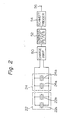
- FIG. 2 there are shown electrical connections of the sensor made up of the piezoelectric sensors 22a and 22b and the sensor made up of the piezoelectric sensors 24a and 24b, and a circuit arrangement for processing outputs of the two sensors to remove noise components therefrom.
- the output signals of the first and second sensors 22 and 24 are sequentially processed by a charge amplifier 50, a low-pass active filter 52 and a Schmitt trigger 54.
- a pulse signal appears at an output terminal 56.
- a vortex train is shed in a known manner in a position downstream of that part of the vortex shedder 12 located inside of the conduit 14 (this part will be referred to as the "shedding portion” hereinafter).
- the vortex train causes the shedding portion of the vortex shedder 12 to oscillate substantially perpendicular to the flow of the fluid through the conduit 14, that is, in the lateral direction as seen in Figure 1.
- the piezoelectric sensors 22a and 22b of the first sensor 22, which is integral with the vortex shedder 12 as mentioned earlier, sense the oscillations to deliver a signal proportional to the oscillation frequency.
- their output levels are added to each other.
- the problem is that the output signal of the first sensor 22 is entraining noise due to external oscillations which propagate through the conduit 14, in addition to the expected oscillations due to the vortex train.
- the piezoelectric sensors 22a and 22b of the first sensor 22 face each other in the direction perpendicular to the fluid flow, they are hardly sensitive to oscillations parallel to the fluid flow and, if sensitive, the resulting outputs would cancel each other to not constitute any noise due to the differential interconnection of the electrodes.
- it comes to externally derived oscillations of the conduit 14 perpendicular to the fluid flow and vortex shedder 12 they are allowed to reach the shedding portion of the shedder 12 to be detected together with the oscillations caused by the vortex train.
- the second sensor 24 is adapted to sense only the external oscillations which are transferred through the conduit 14.
- the vortex shedder 12 is firmly fastened to the conduit 14 by means of the screws 18 and 20 so that the oscillation of the shedding portion of the shedder 12 is prevented from propagating outwardly beyond the fastened position to the remaining outer portion of the shedder 12 (this portion will be referred to as the "compensating portion” hereinafter).
- the second sensor 24, therefore, is immune to oscillation except for those which are introduced into conduit 14 from the outside. It will be noted that the second sensor 24 is common to the first 22 in sensing only the oscillations in the direction perpendicular to the fluid flow and shedder 12.
- both the shedding and compensating portions of the shedder 12 bend to the left to a position indicated by a dash-and-dots line 12c. Therefore, the first and second sensors 22 and 24 translate an external oscillation into a same waveform. Concerning the second sensor 24, however, it senses the composite oscillations of oscillations due to external oscillations and oscillations due to the vortex train.
- the output of the second sensor 24 will cancel a noise component in the output of the first sensor 22 thereby leaving only the signal resulted from the vortex train.
- the sensors 22 and 24 are high impedance elements, their outputs are transformed into voltage variations by the charge amplifier 50.
- the low-pass active filter 52 removes from the voltage variations high frequency components which have no bearing on the oscillations of the vortex shedder 12.
- the Schmitt trigger 54 processes an output of the filter 52 into a rectangular pulse signal which accurately reflects an oscillation frequency provided by the vortex train only. Counting the output pulses of the Schmitt trigger 54 provides any instantaneous flow rate of the fluid 16.
- Another factor that brings about a difference between their characteristic oscillation frequencies is derived externally, e.g., a difference in mass and/or shape between them. Any such difference in oscillation mode between the two portions can be readily eliminated by shifting the balance weight 30 to a desired position on the element 12.
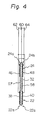
- FIG 4 a modification to the sensor assembly of Figure 1 is illustrated.
- the same reference numerals as those of Figure 1 designate the same structural elements. While in Figure 1 the piezoelectric elements 34 and 36 of the first sensor 22 are physically independent of their adjacent counterparts 42 and 44 of the second sensor 24, in Figure 4 the adjacent piezoelectric elements are replaced by a pair of common piezoelectric elements 57 and 58.
- a terminal 60 is led out from the metal base plate 32; a terminal 62 is led out from the electrodes 38 and 40 which are respectively associated with the elements 57 and 58 of opposite polarities; and a terminal 64 is led out from the electrodes 46 and 48 which are respectively associated with the elements 57 and 58 of opposite polarities.
- FIG. 5 A circuit for processing outputs of the sensors 22 and 24 of Figure 4 is shown in Figure 5, in which the same reference numerals as those of Figure 2 designate the same structural elements.
- the circuit includes a charge amplifier 50a connected to the output terminals 60 and 62 of the first sensor 22, a second charge amplifier 50b connected to the output terminals 60 and 64 of the second oscillation sensor 24, a variable amplifier 66, and an adder or subtractor 68.
- the circuit of Figure 5 will prove effective when the output level of the first sensor 22 differs from that of the second 24.
- the waveform of noise included in the is shown in Figure 5, in which the same reference numerals as those of Figure 2 designate the same structural elements.
- the circuit includes a charge amplifier 50a connected to the output terminals 60 and 62 of the first sensor 22, a second charge amplifier 50b connected to the output terminals 60 and 64 of the second oscillation sensor 24, a variable amplifier 66, and an adder or subtractor 68.
- the circuit of Figure 5 allows the output of the amplifier 66 and - thereby that of the second sensor 24 to be adjusted such that the second sensor output reaches a same level as the first sensor output, which is provided through the charge amplifier 50a. Then, the first and second sensor outputs will be combined by the adder or substractor 68 to remove the noise component.
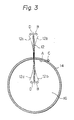
- the first sensor 22 shown in Figure 6 comprises a cylindrical metal tube 70, an annular piezoelectric element 72 mounted on the tube 70, and a pair of metal electrodes 74 and 76, which are individually deposited on the piezoelectric element 72 as by evaporation or gold paste baking in such a manner as to oppose each other.
- the second sensor 24 shares the metal tube 70 with the first sensor 22 and has, in addition thereto, an annular piezoelectric element 78 fit around the tube 70, and a pair of metal electrodes 80 and 82 deposited on the element 78 in the same manner as the electrodes 74 and 76.
- the tube 70, piezoelectric element 72 and electrode 74 constitute one piezoelectric sensor 22a in combination, while the tube 70, piezoelectric element 72 and electrode 76 constitute another piezoelectric sensor 22b which faces the piezoelectric sensor 22a.
- the tube 70 cooperates with the piezoelectric element 78 and electrode 80 to form one piezoelectric sensor 24a, while cooperating with the piezoelectric element 78 and electrode 82 to form another piezoelectric sensor 24b, which faces the piezoelectric sensor 24a.
- the orientation of the sensor assembly inside the element 12 is such that the electrodes 74 and 76 and the electrodes 80 and 82 face each other each in a direction perpendicular to the flow direction of the fluid 12 in the conduit 14.
- the electrodes 74 and 76 located face-to-face in the lateral direction and so are the electrodes 80 and 82, as seen from the upstream or downstream side with respect to the fluid flow.
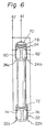
- FIG. 7 Shown in Figure 7 is a modification to the sensor assembly of Figure 6.
- a piezoelectric element 84 covers the whole outer periphery of the metal tube 70, in contrast to the spaced piezoelectric elements 72 and 78 of Figure 6.
- the electrodes 74 and 76 constituting the first sensor 22 are carried on one axial end of the piezoelectric element 84, while the metal electrodes 80 and 82 constituting the second sensor 24 are carried on the other axial end of the same.
- FIG 8. Still another modification to the cylindrical sensor configuration, particularly to that of Figure 6, is shown in Figure 8.
- a pair of spaced piezoelectric elements 72a and 72b are mounted on one end of the metal tube 70 and a pair of spaced piezoelectric elements 78a and 78b on the other end. That is, the piezoelectric element pair 72a-72b is a divided version of the piezoelectric element 72 of Figure 6 and the piezoelectric element pair 78a-78b, that of the piezoelectric element 78.
- circuit shown in Figures 2 and 5 are selectively usable for processing output signals of the cylindrical oscillation sensor assemblies shown in Figures 6-8, just as they are used for the others.
- an oscillation sensor using a piezoelectric element or the like has to have its electrode portions perfectly insulated from the surrounding members by means of glass or the like.
- This has heretofore been implemented by a method which fills the space concerned with glass powder and then heats the glass to melt and harden it, or a method which fills the space with a preformed glass.
- the problem encountered with the use of glass powder is that the filling and heating procedure has to be repeated several times because the volume of glass is smaller in the hardened state after heating than in the initial powdery state.
- the method using a preformed glass invites an increase in cost due to the intricate structure required therefor.
- any one of the cylindrical sensor configurations shown in Figures 6-8 will facilitate the procedure for fixing the sensors within the vortex shedding member 12.
- the present invention provides an oscillation compensating apparatus for a vortex flow meter which offers an excellent signal-to-noise ratio despite its simple and easy-to-produce structure.
- the sensors 22 and 24 may comprise physically separate members which are individually nested in the shedder 12, instead of the integral structure on a single base plate or a tube shown and described.
Landscapes
- Physics & Mathematics (AREA)
- Fluid Mechanics (AREA)
- General Physics & Mathematics (AREA)
- Measuring Volume Flow (AREA)
Applications Claiming Priority (2)
| Application Number | Priority Date | Filing Date | Title |
|---|---|---|---|
| JP57126732A JPS5918422A (ja) | 1982-07-22 | 1982-07-22 | 渦流量計用振動補償装置 |
| JP126732/82 | 1982-07-22 |
Publications (2)
| Publication Number | Publication Date |
|---|---|
| EP0100931A1 EP0100931A1 (en) | 1984-02-22 |
| EP0100931B1 true EP0100931B1 (en) | 1987-06-03 |
Family
ID=14942508
Family Applications (1)
| Application Number | Title | Priority Date | Filing Date |
|---|---|---|---|
| EP83107079A Expired EP0100931B1 (en) | 1982-07-22 | 1983-07-19 | Oscillation compensating apparatus for vortex flow meter |
Country Status (6)
| Country | Link |
|---|---|
| US (1) | US4526040A (enExample) |
| EP (1) | EP0100931B1 (enExample) |
| JP (1) | JPS5918422A (enExample) |
| KR (1) | KR870000458B1 (enExample) |
| CA (1) | CA1189349A (enExample) |
| DE (1) | DE3371941D1 (enExample) |
Cited By (5)
| Publication number | Priority date | Publication date | Assignee | Title |
|---|---|---|---|---|
| EP0144937A3 (en) * | 1983-12-02 | 1987-07-15 | Oval Engineering Co., Ltd. | Vortex flow meter |
| US4716770A (en) * | 1985-12-13 | 1988-01-05 | Flowtec Ag | Vortex flow meter |
| DE4441129A1 (de) * | 1994-11-21 | 1996-05-23 | Junkalor Gmbh | Meßwertgeber für einen Wirbeldurchflußmesser |
| DE19723006A1 (de) * | 1997-06-02 | 1998-12-03 | Bailey Fischer & Porter Gmbh | Verfahren und Meßeinrichtung mit Sensoranordnung zur Signalerfassung und -verarbeitung bei Wirbel- und Dralldurchflußmessern |
| US5869772A (en) * | 1996-11-27 | 1999-02-09 | Storer; William James A. | Vortex flowmeter including cantilevered vortex and vibration sensing beams |
Families Citing this family (31)
| Publication number | Priority date | Publication date | Assignee | Title |
|---|---|---|---|---|
| EP0110321B1 (en) * | 1982-11-25 | 1988-09-07 | Oval Engineering Co., Ltd. | Vortex flow meter |
| JPS6023721U (ja) * | 1983-07-26 | 1985-02-18 | オ−バル機器工業株式会社 | 渦流量計渦検出装置 |
| JPS607024U (ja) * | 1983-06-28 | 1985-01-18 | オ−バル機器工業株式会社 | 微小変動圧力検出器 |
| JPS6130823U (ja) * | 1984-07-27 | 1986-02-24 | オ−バル機器工業株式会社 | 渦流量計 |
| US4862750A (en) * | 1987-02-11 | 1989-09-05 | Nice Gerald J | Vortex shedding fluid velocity meter |
| US5095760A (en) * | 1989-05-08 | 1992-03-17 | Lew Hyok S | Vortex flowmeter with dual sensors |
| US4984471A (en) * | 1989-09-08 | 1991-01-15 | Fisher Controls International, Inc. | Force transmitting mechanism for a vortex flowmeter |
| US5209125A (en) * | 1989-12-22 | 1993-05-11 | The Foxboro Company | Piezoelectric pressure sensor |
| US5003827A (en) * | 1989-12-22 | 1991-04-02 | The Foxboro Company | Piezoelectric differential pressure vortex sensor |
| US5313843A (en) * | 1990-01-29 | 1994-05-24 | Fuji Electric Co., Ltd. | Karman vortex flow meter |
| US5197336A (en) * | 1990-01-29 | 1993-03-30 | Fuji Electric Co., Ltd. | Karman vortex flow meter |
| US5220842A (en) * | 1990-12-31 | 1993-06-22 | Lew Hyok S | Vortex generator-sensor with pivotally balanced mass distribution |
| US5247838A (en) * | 1991-12-19 | 1993-09-28 | Badger Meter, Inc. | Double wing vortex flowmeter |
| DE4143202C1 (enExample) * | 1991-12-30 | 1993-02-04 | Rota Yokogawa Gmbh & Co Kg, 7867 Wehr, De | |
| US5347873A (en) * | 1993-04-09 | 1994-09-20 | Badger Meter, Inc. | Double wing vortex flowmeter with strouhal number corrector |
| US5561249A (en) * | 1993-12-23 | 1996-10-01 | Nice; Gerald J. | Insertable flow meter with dual sensors |
| KR100232471B1 (ko) * | 1996-06-05 | 1999-12-01 | 류정열 | 차체 진동을 고려한 연료량 검출방법 |
| US5804740A (en) * | 1997-01-17 | 1998-09-08 | The Foxboro Company | Capacitive vortex mass flow sensor |
| US7073394B2 (en) * | 2004-04-05 | 2006-07-11 | Rosemount Inc. | Scalable averaging insertion vortex flow meter |
| US6973841B2 (en) * | 2004-04-16 | 2005-12-13 | Rosemount Inc. | High pressure retention vortex flow meter with reinforced flexure |
| JP4158980B2 (ja) * | 2004-07-15 | 2008-10-01 | 株式会社オーバル | マルチ渦流量計 |
| KR100868046B1 (ko) * | 2006-11-28 | 2008-11-11 | 주식회사 세 바 | 와류식 유량계 |
| DE102008025365A1 (de) | 2008-05-27 | 2009-12-03 | Stübbe, Peter | Nicht invasive Zahnbrücke und das Verfahren und die Vorrichtung zu ihrer Herstellung |
| DE102010056279B4 (de) | 2010-12-24 | 2013-07-04 | Abb Technology Ag | Vortex-Durchflussmessgerät mit optimierter Temperaturerfassung |
| CN102279025B (zh) * | 2011-06-30 | 2013-02-20 | 福建上润精密仪器有限公司 | 插入式传感器集成体的集成式气体质量流量计 |
| DE102012220505B4 (de) * | 2012-11-09 | 2016-10-20 | Gestra Ag | Überwachung eines Kondensatableiters |
| GB201300403D0 (en) * | 2013-01-10 | 2013-02-20 | Smiths Medical Int Ltd | Flow sensors and apparatus |
| US9513147B2 (en) * | 2013-11-04 | 2016-12-06 | South Jersey Engineering & Research, LLC | Flowmeter comprising piezoelectric sensor |
| CN105006991A (zh) * | 2015-07-22 | 2015-10-28 | 上海交通大学 | 叠层压电式井下能量采集装置 |
| JP2017067726A (ja) * | 2015-10-02 | 2017-04-06 | サーパス工業株式会社 | カルマン渦流量計 |
| FR3117589B1 (fr) | 2020-12-11 | 2023-07-28 | La Rochelle Univ | Dispositif de mesure d’au moins un paramètre d'écoulement d'un fluide |
Family Cites Families (9)
| Publication number | Priority date | Publication date | Assignee | Title |
|---|---|---|---|---|
| JPS5115467A (en) * | 1974-07-29 | 1976-02-06 | Hokushin Electric Works | Karumanuzuoryoshita daikokeiryuryokei |
| US3991613A (en) * | 1975-03-10 | 1976-11-16 | Corning Glass Works | Sensing element for flow meter |
| US4186599A (en) * | 1976-12-29 | 1980-02-05 | Rosemount Inc. | Vortex shedding flowmeter assembly |
| GB1601548A (en) * | 1977-05-30 | 1981-10-28 | Yokogawa Electric Works Ltd | Flow metering apparatus |
| GB2008752B (en) * | 1977-11-14 | 1982-03-31 | Yokogawa Electric Works Ltd | Vortex flow meter |
| DD141352A1 (de) * | 1979-02-09 | 1980-04-23 | Gisela Schmiedeberg | Anordnung zur wirbel-volumenstrommessung |
| US4270391A (en) * | 1979-08-24 | 1981-06-02 | Fischer & Porter Co. | Frequency-responsive filter for flowmeter transmission system |
| US4362061A (en) * | 1981-02-04 | 1982-12-07 | Yokogawa Electric Works, Ltd. | Vortex shedding flow measuring device |
| JPS5860217A (ja) * | 1981-10-06 | 1983-04-09 | Yokogawa Hokushin Electric Corp | 渦流量計 |
-
1982
- 1982-07-22 JP JP57126732A patent/JPS5918422A/ja active Granted
-
1983
- 1983-07-18 US US06/515,090 patent/US4526040A/en not_active Expired - Lifetime
- 1983-07-19 DE DE8383107079T patent/DE3371941D1/de not_active Expired
- 1983-07-19 EP EP83107079A patent/EP0100931B1/en not_active Expired
- 1983-07-21 KR KR1019830003366A patent/KR870000458B1/ko not_active Expired
- 1983-07-21 CA CA000432864A patent/CA1189349A/en not_active Expired
Cited By (6)
| Publication number | Priority date | Publication date | Assignee | Title |
|---|---|---|---|---|
| EP0144937A3 (en) * | 1983-12-02 | 1987-07-15 | Oval Engineering Co., Ltd. | Vortex flow meter |
| US4716770A (en) * | 1985-12-13 | 1988-01-05 | Flowtec Ag | Vortex flow meter |
| DE4441129A1 (de) * | 1994-11-21 | 1996-05-23 | Junkalor Gmbh | Meßwertgeber für einen Wirbeldurchflußmesser |
| US5627322A (en) * | 1994-11-21 | 1997-05-06 | Bopp & Reuther Messtechnik Gmbh | Measurement sensor for a vortex flowmeter |
| US5869772A (en) * | 1996-11-27 | 1999-02-09 | Storer; William James A. | Vortex flowmeter including cantilevered vortex and vibration sensing beams |
| DE19723006A1 (de) * | 1997-06-02 | 1998-12-03 | Bailey Fischer & Porter Gmbh | Verfahren und Meßeinrichtung mit Sensoranordnung zur Signalerfassung und -verarbeitung bei Wirbel- und Dralldurchflußmessern |
Also Published As
| Publication number | Publication date |
|---|---|
| EP0100931A1 (en) | 1984-02-22 |
| KR870000458B1 (ko) | 1987-03-11 |
| CA1189349A (en) | 1985-06-25 |
| JPS6332127B2 (enExample) | 1988-06-28 |
| KR840005552A (ko) | 1984-11-14 |
| JPS5918422A (ja) | 1984-01-30 |
| DE3371941D1 (en) | 1987-07-09 |
| US4526040A (en) | 1985-07-02 |
Similar Documents
| Publication | Publication Date | Title |
|---|---|---|
| EP0100931B1 (en) | Oscillation compensating apparatus for vortex flow meter | |
| US5492016A (en) | Capacitive melt pressure measurement with center-mounted electrode post | |
| US6352000B1 (en) | Vortex flow sensor | |
| US5224383A (en) | Melt pressure measurement and the like | |
| KR100186887B1 (ko) | 전자유량계 및 유량의 전자측정방법 | |
| EP0282251A2 (en) | Fluid transducer | |
| US4437350A (en) | Vortex flow metering apparatus | |
| US4201084A (en) | Vortex flow meter | |
| EP0083144A1 (en) | Improved method and apparatus for mass flow measurement | |
| US4760744A (en) | Mass flow meter based on the coriolis principle | |
| EP0110321B1 (en) | Vortex flow meter | |
| EP0364508A4 (en) | Vortex flowmeter | |
| CA2050915C (en) | Piezoelectric differential pressure vortex sensor | |
| JPS6332126B2 (enExample) | ||
| EP0415627B1 (en) | Acceleration sensor and acceleration sensing system | |
| DE2827985C2 (de) | Strömungsmesser | |
| US7523662B2 (en) | Process meter | |
| US6408700B1 (en) | Mass flow rate measurement circuit and method for a mass flow/density meter | |
| RU2083988C1 (ru) | Молекулярно-электронный преобразователь колебательных ускорений | |
| JP4648625B2 (ja) | 渦流量計 | |
| JP3049176B2 (ja) | 渦流量計および渦センサ | |
| GB2068551A (en) | Vortex Shedding Flow Measuring Device | |
| JP4670152B2 (ja) | 渦流量計 | |
| KR890000690B1 (ko) | 압전 센서(sensor) | |
| JPH05118889A (ja) | 渦流量計 |
Legal Events
| Date | Code | Title | Description |
|---|---|---|---|
| PUAI | Public reference made under article 153(3) epc to a published international application that has entered the european phase |
Free format text: ORIGINAL CODE: 0009012 |
|
| AK | Designated contracting states |
Designated state(s): CH DE FR GB LI NL |
|
| 17P | Request for examination filed |
Effective date: 19840731 |
|
| GRAA | (expected) grant |
Free format text: ORIGINAL CODE: 0009210 |
|
| AK | Designated contracting states |
Kind code of ref document: B1 Designated state(s): CH DE FR GB LI NL |
|
| REF | Corresponds to: |
Ref document number: 3371941 Country of ref document: DE Date of ref document: 19870709 |
|
| ET | Fr: translation filed | ||
| PLBE | No opposition filed within time limit |
Free format text: ORIGINAL CODE: 0009261 |
|
| STAA | Information on the status of an ep patent application or granted ep patent |
Free format text: STATUS: NO OPPOSITION FILED WITHIN TIME LIMIT |
|
| 26N | No opposition filed | ||
| PGFP | Annual fee paid to national office [announced via postgrant information from national office to epo] |
Ref country code: GB Payment date: 19980703 Year of fee payment: 16 |
|
| PGFP | Annual fee paid to national office [announced via postgrant information from national office to epo] |
Ref country code: FR Payment date: 19980717 Year of fee payment: 16 |
|
| PGFP | Annual fee paid to national office [announced via postgrant information from national office to epo] |
Ref country code: NL Payment date: 19980728 Year of fee payment: 16 |
|
| PGFP | Annual fee paid to national office [announced via postgrant information from national office to epo] |
Ref country code: CH Payment date: 19980818 Year of fee payment: 16 |
|
| PGFP | Annual fee paid to national office [announced via postgrant information from national office to epo] |
Ref country code: DE Payment date: 19980827 Year of fee payment: 16 |
|
| PG25 | Lapsed in a contracting state [announced via postgrant information from national office to epo] |
Ref country code: GB Free format text: LAPSE BECAUSE OF NON-PAYMENT OF DUE FEES Effective date: 19990719 |
|
| PG25 | Lapsed in a contracting state [announced via postgrant information from national office to epo] |
Ref country code: LI Free format text: LAPSE BECAUSE OF NON-PAYMENT OF DUE FEES Effective date: 19990731 Ref country code: FR Free format text: THE PATENT HAS BEEN ANNULLED BY A DECISION OF A NATIONAL AUTHORITY Effective date: 19990731 Ref country code: CH Free format text: LAPSE BECAUSE OF NON-PAYMENT OF DUE FEES Effective date: 19990731 |
|
| PG25 | Lapsed in a contracting state [announced via postgrant information from national office to epo] |
Ref country code: NL Free format text: LAPSE BECAUSE OF NON-PAYMENT OF DUE FEES Effective date: 20000201 |
|
| GBPC | Gb: european patent ceased through non-payment of renewal fee |
Effective date: 19990719 |
|
| REG | Reference to a national code |
Ref country code: CH Ref legal event code: PL |
|
| NLV4 | Nl: lapsed or anulled due to non-payment of the annual fee |
Effective date: 20000201 |
|
| PG25 | Lapsed in a contracting state [announced via postgrant information from national office to epo] |
Ref country code: DE Free format text: LAPSE BECAUSE OF NON-PAYMENT OF DUE FEES Effective date: 20000503 |
|
| REG | Reference to a national code |
Ref country code: FR Ref legal event code: ST |