EP0100009A1 - Dispositif de mesure non destructive de la profondeur de trempe de matériaux - Google Patents
Dispositif de mesure non destructive de la profondeur de trempe de matériaux Download PDFInfo
- Publication number
- EP0100009A1 EP0100009A1 EP83106710A EP83106710A EP0100009A1 EP 0100009 A1 EP0100009 A1 EP 0100009A1 EP 83106710 A EP83106710 A EP 83106710A EP 83106710 A EP83106710 A EP 83106710A EP 0100009 A1 EP0100009 A1 EP 0100009A1
- Authority
- EP
- European Patent Office
- Prior art keywords
- field strength
- frequency
- noise
- maximum
- tangential
- Prior art date
- Legal status (The legal status is an assumption and is not a legal conclusion. Google has not performed a legal analysis and makes no representation as to the accuracy of the status listed.)
- Granted
Links
Images

Classifications
-
- G—PHYSICS
- G01—MEASURING; TESTING
- G01R—MEASURING ELECTRIC VARIABLES; MEASURING MAGNETIC VARIABLES
- G01R33/00—Arrangements or instruments for measuring magnetic variables
- G01R33/12—Measuring magnetic properties of articles or specimens of solids or fluids
- G01R33/14—Measuring or plotting hysteresis curves
-
- G—PHYSICS
- G01—MEASURING; TESTING
- G01B—MEASURING LENGTH, THICKNESS OR SIMILAR LINEAR DIMENSIONS; MEASURING ANGLES; MEASURING AREAS; MEASURING IRREGULARITIES OF SURFACES OR CONTOURS
- G01B7/00—Measuring arrangements characterised by the use of electric or magnetic techniques
- G01B7/02—Measuring arrangements characterised by the use of electric or magnetic techniques for measuring length, width or thickness
- G01B7/06—Measuring arrangements characterised by the use of electric or magnetic techniques for measuring length, width or thickness for measuring thickness
- G01B7/10—Measuring arrangements characterised by the use of electric or magnetic techniques for measuring length, width or thickness for measuring thickness using magnetic means, e.g. by measuring change of reluctance
Definitions
- the invention relates to a device for measuring material properties with a magnetization yoke that can be placed on the material to be examined with its two magnetic poles, the excitation coil for controlling the hysteresis curve of the material to be examined is connected to a bipolar power supply unit and an H-field meter between its magnetic poles Detection of the tangential field strength is arranged.
- Such a device is known from DE-A1-30 37 932 and, in addition to the H-field meter between the magnetic poles, has an inductive pickup for detecting the Barkhausen noise or an eddy current coil, with the aid of which the superimposition permeability of the material during the control of the hysteresis curve is detectable.
- the device equipped with an inductive transducer determines the coercive field strength of the material under investigation by evaluating the noise maximum and determining the tangential field strength assigned to the noise maximum
- the device equipped with the eddy current coil determines the coercive field strength in that the impedance of the material under investigation, which is dependent on the superimposed permeability of the material under investigation, is the current impedance and the tangential field strength assigned to the maximum impedance is used to determine the coercive field strength.
- Both the device equipped with the inductive transducer for detecting the Barkhausen noise and the device equipped with the eddy current coil only allow a statement about the coercive field strength present in the respective interaction volume of the measuring devices without any statement about their distribution. For this reason, measurements of the coercive field strength can only make global statements about the mechanical hardness, which often correlates with the coercive field strength (Zeitschrift für Metallischen, Vol. 46 (1955), H. 5, pp. 364/365).
- the invention has for its object to provide devices of the type mentioned that allow a determination of the hardness course perpendicular to the surface of the material under investigation.
- the inductive pickup feeds the circuit measuring the Barkhausen noise via an adjustable filter, the pass frequency of which can be increased by an evaluation circuit during a measuring cycle until the basic structure assigned noise maximum occurring at the coercive field strength of the basic structure is suppressed and only the noise maximum occurring at the coercive field strength of the covering structure can be measured, and that the hardening depth associated with the limit frequency determined by the evaluation circuit can be displayed on a display device.
- the arrangement according to the invention is such that the impedance measuring circuit is assigned an evaluation circuit by means of which the test frequency of the alternating current generator feeding the eddy current coil can be adjusted and by which the test frequency assigned to the hardening depth can be determined, by changing the test frequency a maximum change in the tangential field strength associated with an impedance maximum during the control of the hysteresis curve can be triggered.
- the invention thus makes it possible not only to determine the hardness of the material sample by determining the coercive field strength, but also how thick the hardened cover layer present on a material sample is.
- laborious metallographic destructive test methods can be dispensed with, in which a grinding must be carried out perpendicular to the surface of the test specimen in order to determine the hardening depth by microhardness measurement.
- the invention is also distinguished by the fact that the hardness depth can be determined quickly with little measurement effort using the mounting technique.
- a test piece 1 is shown enlarged and schematically, which consists of a ferromagnetic material and has a hard cover layer 3 on a relatively soft basic structure 2.
- the device according to the invention shown schematically in FIG. 1 allows the thickness of the cover layer 3 and thus the depth of hardening to be determined non-destructively.
- a magnetization yoke 5 is placed on the surface 4 of the test object 1, the excitation coil 6 of which is schematically shown by a few turns and is connected to the outputs of a bipolar power supply unit 7.
- the bipolar power supply unit 7 is controlled with the aid of a function generator 8, so that the bipolar power supply unit 7, for example, impresses a sawtooth-shaped current into the excitation coil 6.
- This creates alternately a north pole and a south pole at the ends 9 of the magnetization yoke 5 and in the magnetic circuit closed via the test specimen a magnetic flux through which the hysteresis curve of the test specimen 1 with the cover layer 3 and the basic structure 2 is controlled.
- the frequency of the control is between 0.1 and 1000 Hz, preferably between about 20 and 200 Hz.
- the Bloch walls of the test specimen 1 are held in interaction with lattice defects and among themselves in potential wells. Due to the magnetic field generated by the magnetizing yoke 5, forces are exerted on the Bloch walls and as soon as a potential mountain is exceeded, the relevant Bloch wall moves until it sticks to another potential mountain. This pulse-like change in magnetization induces a spectrum of micro eddy currents that can be measured on the surface 4 of the test specimen 1. A more precise resolution of the hysteresis curve shows that it actually has a sawtooth shape and that the test specimen 1 is not only magnetized continuously, but that sudden changes in magnetization occur.
- the erratic Blochwandbawegungen which represent a Barkhausen event, thus generate a continuous spectrum of eddy currents, the individual frequency components are attenuated differently on their way to the surface 4 due to the frequency-dependent eddy current damping.
- the Barkhausen noise emanating both from the basic structure 2 and from the cover layer 3 during the control of the hysteresis curve is detected with the aid of an inductive pickup 10, which is against the surface 4 of the device under test 1.
- the inductive pickup 10 can be designed as an air coil or as a tape head and is connected via a shielded line 11 to a preamplifier 12, the gain of which can be, for example, 60 dB.
- the broadband spectrum of Barkhausen noise available at the output of the preamplifier 12 passes through a filter 13 to a rectifier 14, so that a variable DC voltage occurs at the rectifier output 15, the amplitude of which corresponds to the noise signal passed by the filter 13.
- the Barkhausen noise generated in the device under test 1 changes its amplitude while the hysteresis curve is being controlled. Since the magnetization change is maximum with respect to the path when a 180 ° Bloch wall is moved, the maximum noise occurs with iron materials where 180 ° Bloch walls are preferably moved. This is the case with the coercive force H c .
- the coercive field strength H c is correlated with the hardness, so that the tangential field strength present at the maximum noise on the surface 4 of the test specimen 1 is a measure of the hardness present in the interaction volume of the measuring arrangement.
- an H-field meter 16 is arranged between the magnetic poles of the magnetizing yoke 5 in the vicinity of the inductive pickup 10, which can be implemented, for example, as a Hall probe.
- the H-field meter 16 like the rectifier output 15, is also electrically connected to an evaluation circuit 17 which, among other things, determines which of the H field meter 16 measured tangential field strength a noise maximum occurs. In the case of a homogeneous test specimen, there is only a noise maximum for a certain positive tangential field strength and a corresponding noise maximum for the same but the opposite direction of the tangential field strength.
- These tangential field strengths representing the coercive field strength H c can be output by the evaluation circuit 17 via a display device 18.
- the filter 13 can be adjusted in its pass frequency via a control line 19 through the evaluation circuit 17.
- the filter 13 can be designed as a band filter or as a high-pass filter.
- An adjustment is possible via the control line 19 in such a way that the center frequency in the case of a bandpass filter can be adjusted between approximately 1 kHz and 500 kHz or in the event of a high pass the limit frequency can be adjusted between approximately 1 kHz and 500 kHz.
- the analysis frequency supplied to the rectifier 14 can be shifted to higher or lower frequencies.
- the frequency-dependent eddy current damping the high-frequency components of the Barkhausen noise of the basic structure 2 reach the surface 4 only considerably weakened.
- the high-frequency components of the Barkhausen noise of the cover layer 3 are only slightly weakened because of the immediate proximity to the surface 4.
- a predetermined setting of the center frequency or the cutoff frequency of the filter 13 in the positive range and in the negative range of the tangential field strength 2 noise maxima occur, of which that of an absolutely smaller tangential field strength the softer basic structure 2 and that which is caused by the harder cover layer 3 associated with an absolutely larger tangential field strength, it can be achieved by increasing the filter frequency that the noise maximum associated with the basic structure 2 is suppressed more and more because the high frequencies of the Barkhausen noise their relatively long way to the surface 4 are suppressed more than the corresponding frequencies of the Barkhausen noise due to the cover layer 3.
- the filter frequency is increased via the control circuit closed by the evaluation circuit 17, the filter 13 and the rectifier 14 until the Barkhausen noise associated with the softer basic structure 2 can no longer be determined.
- the frequency of the filter 13 then determined by the evaluation circuit 17 via the control line 19 is a measure of the distance of the basic structure 2 from the surface 4 and thus a measure of the hardening depth and the thickness of the covering layer 3. The greater the hardening depth and the thicker the Cover layer 3, the more the high-frequency components in the Barkhausen noise of the basic structure 2 disappear and the lower the cut-off frequency or center frequency of the filter 13 determined by the evaluation circuit 17 when the noise maximum of the Barkhausen noise of the basic structure 2 is just suppressed.
- the evaluation circuit 17 calculates the analysis depth associated with the cut-off frequency or center frequency of the filter 13 on the basis of the above-mentioned frequency-dependent eddy current damping and displays the result on the display device 18.
- the device shown in FIG. 1 thus makes it possible, on the one hand, to determine the depth of hardness of the cover layer 3 by determining a frequency and an associated damping path.
- the device shown in FIG. 1 allows the coercive field strength of the basic structure 2 to be determined on the basis of the position of the first noise maximum with respect to the tangential field strength and the coercive field strength of the cover layer 3 due to the position of the second noise maximum with respect to the tangential field strength and to be displayed on the display device 18.
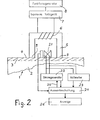
- FIG. 2 shows a further exemplary embodiment of the invention, which also allows the depth of hardness to be measured.
- Fig. 2 which correspond to the parts shown in Fig. 1, are given the same reference numerals.
- the device under test 1 with the basic structure 2, the cover structure 3 and the surface 4 on which the magnetization yoke 5 with the excitation coil 6 is placed, which is excited via a bipolar power supply unit 7, the output current of which is related to the frequency and the shape is determined by the function generator 8.
- the frequency of the function generator 8 and thus the frequency of the control of the hysteresis curve is between approximately 0.1 and 1000 Hz. It is preferably approximately 20 to 200 Hz.
- an H-field meter 16 is arranged between the ends 9 of the magnetizing yoke 5, through which the respective Tangential field strength is measured while driving through the hysteresis curve.
- the superimposition permeability changes while the hysteresis curve is being controlled. It has a maximum in the vicinity of the coercive field strength H c .
- the device shown in FIG. 2 has an eddy current coil 21, which can be designed as a pancake coil or a ferrite yoke and is supplied with an alternating current by a current generator 22, the frequency of which is significant is higher than the frequency with which the hysteresis curve is controlled.
- a current generator 22 the frequency of which is significant is higher than the frequency with which the hysteresis curve is controlled.
- the impedance of the eddy current coil 21 can be determined from the respective current and the respective voltage.
- the impedance determined in each case is a function of the superimposition permeability and is therefore greatest in the case of the coercive field strength. For this reason, there is a maximum of the impedance of the eddy current coil 21 if the tangential field strength detected by the H-field meter corresponds to the coercive field strength.
- the evaluation circuit 24 determines the respective impedance of the eddy current coil 21 from the current values impressed by the current generator 22 and the voltage values measured by the voltmeter 23 and allows the determination and display of the tangential field strength at which the measured or calculated impedance is maximum.
- the test frequency of the current generator 22 can be adjusted via a control line 25 by the evaluation circuit 24 between 1 kHz and 100 MHz, preferably between 20 kHz and 2 MHz.
- a depth of penetration 0 results for the field of the eddy current coil 21 according to the equation where f is the test frequency, ⁇ is the superimposition permeability and ⁇ is the conductivity of the respective medium.
- the evaluation circuit 24 is therefore able to determine the penetration depth of the field of the eddy current coil 21 by changing the test frequency of the current generator 22.
- the evaluation circuit 24 is constructed so that it during a Depth profile measurement, in which the hysteresis curve is controlled several times, increases the test frequency of the current generator 22 after each controlled hysteresis curve. This continuously reduces the depth of analysis and the interaction volume. At very low test frequencies and high analysis depths, the position of the maximum of the impedance calculated by the evaluation circuit 24 shifts only insignificantly with respect to the tangential field strength detected by the H-field meter.
- the evaluation circuit 24 determines the tangential field strengths for all hysteresis curves at which the impedance of the eddy current coil 21 is at a maximum. By comparing the changes in position of the impedance maxima with given test frequency changes, the evaluation circuit determines the test frequency at which a frequency change triggers a maximum change in position of the impedance maximum with respect to the absolute tangential field strength. This test frequency is a measure of the hardening depth and the thickness of the cover layer 3.
- the evaluation circuit 24 taking into account the superimposition permeability and the conductivity, for example, assumed to be constant, allows a calculation of the penetration depth assigned to the test frequency determined in the manner described above. This depth of penetration can be displayed on a display device 26 immediately or after correction by a constant and / or a correction factor.
- the exemplary embodiment of the invention shown in FIG. 2 thus allows a test frequency to be determined and the hardness depth to be derived therefrom.
Priority Applications (1)
| Application Number | Priority Date | Filing Date | Title |
|---|---|---|---|
| AT83106710T ATE16532T1 (de) | 1982-07-09 | 1983-07-08 | Vorrichtung zum zerstoerungsfreien messen der einhaertetiefe von werkstoffen. |
Applications Claiming Priority (2)
| Application Number | Priority Date | Filing Date | Title |
|---|---|---|---|
| DE3225743 | 1982-07-09 | ||
| DE3225743 | 1982-07-09 |
Publications (2)
| Publication Number | Publication Date |
|---|---|
| EP0100009A1 true EP0100009A1 (fr) | 1984-02-08 |
| EP0100009B1 EP0100009B1 (fr) | 1985-11-13 |
Family
ID=6168059
Family Applications (1)
| Application Number | Title | Priority Date | Filing Date |
|---|---|---|---|
| EP83106710A Expired EP0100009B1 (fr) | 1982-07-09 | 1983-07-08 | Dispositif de mesure non destructive de la profondeur de trempe de matériaux |
Country Status (3)
| Country | Link |
|---|---|
| EP (1) | EP0100009B1 (fr) |
| AT (1) | ATE16532T1 (fr) |
| DE (1) | DE3361224D1 (fr) |
Cited By (17)
| Publication number | Priority date | Publication date | Assignee | Title |
|---|---|---|---|---|
| WO1985003577A1 (fr) * | 1984-02-07 | 1985-08-15 | Wolfgang Stengel | Essai non destrucif de materiaux pour substances ferromagnetiques |
| EP0287873A2 (fr) * | 1987-04-16 | 1988-10-26 | Siemens Aktiengesellschaft | Procédé pour mesurer et localiser avec précision des forces élastiques dans des domaines trempés d'éléments de construction |
| WO1988010420A2 (fr) * | 1987-06-27 | 1988-12-29 | Stiftung Institut für Werkstofftechnik | Procede pour detecter l'etat de la couche superficielle de corps |
| EP0531042A2 (fr) * | 1991-09-04 | 1993-03-10 | Iowa State University Research Foundation, Inc. | Système et méthode pour l'évaluation des caractéristiques de la surface d'un matériau magnétique |
| EP0595117A1 (fr) * | 1992-10-21 | 1994-05-04 | Fraunhofer-Gesellschaft Zur Förderung Der Angewandten Forschung E.V. | Appareil pour l'examen non-destructif avec résolution spatiale des paramètres magnétiques |
| WO1996010744A1 (fr) * | 1993-09-30 | 1996-04-11 | Pro Innovatio Forschungszentrum Für Hochtechnologie Und Industrielle Anwendung Gmbh | Procede et dispositif permettant d'obtenir de façon selective des valeurs appropriees pour le controle local, en continu, de parametres de surface |
| FR2743148A1 (fr) * | 1995-12-29 | 1997-07-04 | Framatome Sa | Dispositif et procede de controle de tubes par courants de foucault |
| EP1767932A1 (fr) * | 2005-09-23 | 2007-03-28 | Fraunhofer-Gesellschaft zur Förderung der angewandten Forschung e.V. | Dispositif et procédé destinés à la vérification non destructive de composants |
| US8436608B2 (en) | 2009-09-21 | 2013-05-07 | General Electric Company | Eddy current inspection system and method |
| DE102012205676A1 (de) | 2012-04-05 | 2013-10-10 | Zf Friedrichshafen Ag | Verfahren zum Kalibrieren einer Messvorrichtung zur Oberflächenprüfung basierend auf Barkhausenrauschen für eine vorbestimmte Bauteilgeometrie |
| DE102012205677A1 (de) | 2012-04-05 | 2013-10-10 | Zf Friedrichshafen Ag | Verfahren zur Prüfung eines Bauteils basierend auf Barkhausenrauschen |
| EP2706351A3 (fr) * | 2012-09-07 | 2014-04-02 | Fraunhofer-ges. zur Förderung der Angewandten Forschung E.V. | Procédé, dispositif et utilisation du dispositif pour la détermination quantitative non destructive de l'épaisseur de couche d'un corps présentant des couches |
| WO2015081352A1 (fr) * | 2013-12-02 | 2015-06-11 | Ceratizit Austria Gesellschaft M.B.H. | Procédé de caractérisation de corps en métal dur |
| WO2016085382A1 (fr) * | 2014-11-28 | 2016-06-02 | Scania Cv Ab | Procédé d'étalonnage d'agencement d'évaluation pour détecter un bruit de barkhausen magnétique |
| WO2016096661A1 (fr) * | 2014-12-17 | 2016-06-23 | Compagnie Generale Des Etablissements Michelin | Procédé de mesure de l'épaisseur d'une couche de matériau caoutchouteux |
| EP3056897A1 (fr) | 2015-02-13 | 2016-08-17 | Pentacon Gmbh Foto- Und Feinwerktechnik | Procede et dispositif de controle de l'homogeneite de pieces usinees ferromagnetiques, en particulier le controle de fissure et/ou de surchauffe de meulage |
| CN109991308A (zh) * | 2019-03-18 | 2019-07-09 | 北京工业大学 | 薄带钢综合力学性能的微磁无损在线检测系统 |
Families Citing this family (7)
| Publication number | Priority date | Publication date | Assignee | Title |
|---|---|---|---|---|
| DE112011105011B4 (de) * | 2011-03-07 | 2014-08-28 | Toyota Jidosha Kabushiki Kaisha | Vorrichtung zur Spezifizierung einer Koerzitivfeldstärke |
| DE102014114226A1 (de) | 2014-09-30 | 2016-03-31 | Rohmann Gmbh | Wirbelstromprüfung mit Impulsmagnetisierung |
| CN105717191A (zh) * | 2016-01-28 | 2016-06-29 | 中国特种设备检测研究院 | 磁巴克豪森噪声信号和磁性参数的检测方法和装置 |
| CN105548924A (zh) * | 2016-01-28 | 2016-05-04 | 中国特种设备检测研究院 | 磁巴克豪森及磁性参数传感器和测量方法 |
| CN105866234B (zh) * | 2016-03-23 | 2019-09-06 | 重庆大学 | 电涡流和巴克豪森相融合的铁磁材料无损检测仪器和方法 |
| CN105911489B (zh) * | 2016-04-10 | 2018-11-02 | 北京工业大学 | 共源双频励磁式多功能微磁信号同步检测方法 |
| CN105784833A (zh) * | 2016-05-17 | 2016-07-20 | 中国特种设备检测研究院 | 多磁参数传感器 |
Citations (2)
| Publication number | Priority date | Publication date | Assignee | Title |
|---|---|---|---|---|
| DE2837733A1 (de) * | 1978-08-30 | 1980-03-27 | Fraunhofer Ges Forschung | Verfahren zur zerstoerungsfreien feststellung von werkstoffzustaenden unter ausnutzung des barkhausen-effektes |
| DE3037932A1 (de) * | 1980-10-08 | 1982-04-15 | Fraunhofer-Gesellschaft zur Förderung der angewandten Forschung e.V., 8000 München | Verfahren zur feststellung der koerzitivfeldstaerken an ausgedehnten oberflaechen mit magnetinduktiven und magnetoelastischen messgroessen |
-
1983
- 1983-07-08 DE DE8383106710T patent/DE3361224D1/de not_active Expired
- 1983-07-08 EP EP83106710A patent/EP0100009B1/fr not_active Expired
- 1983-07-08 AT AT83106710T patent/ATE16532T1/de not_active IP Right Cessation
Patent Citations (2)
| Publication number | Priority date | Publication date | Assignee | Title |
|---|---|---|---|---|
| DE2837733A1 (de) * | 1978-08-30 | 1980-03-27 | Fraunhofer Ges Forschung | Verfahren zur zerstoerungsfreien feststellung von werkstoffzustaenden unter ausnutzung des barkhausen-effektes |
| DE3037932A1 (de) * | 1980-10-08 | 1982-04-15 | Fraunhofer-Gesellschaft zur Förderung der angewandten Forschung e.V., 8000 München | Verfahren zur feststellung der koerzitivfeldstaerken an ausgedehnten oberflaechen mit magnetinduktiven und magnetoelastischen messgroessen |
Non-Patent Citations (1)
| Title |
|---|
| JOURNAL PHYSICS E: SCIENTIFIC INSTRUMENTS, Band 11, 1978, London R. TER STEGE et al. "Equipment for the investigation of statistical properties of the Barkhausen effect", Seiten 791-793 * |
Cited By (28)
| Publication number | Priority date | Publication date | Assignee | Title |
|---|---|---|---|---|
| WO1985003577A1 (fr) * | 1984-02-07 | 1985-08-15 | Wolfgang Stengel | Essai non destrucif de materiaux pour substances ferromagnetiques |
| EP0287873A2 (fr) * | 1987-04-16 | 1988-10-26 | Siemens Aktiengesellschaft | Procédé pour mesurer et localiser avec précision des forces élastiques dans des domaines trempés d'éléments de construction |
| US4881030A (en) * | 1987-04-16 | 1989-11-14 | Siemens Aktinegesellschaft | Method and apparatus for measuring and precisely locating internal tensile stresses in hardened regions of components by measuring coercive field strength and barkhausen noise amplitude |
| EP0287873A3 (fr) * | 1987-04-16 | 1991-02-27 | Siemens Aktiengesellschaft | Procédé pour mesurer et localiser avec précision des forces élastiques dans des domaines trempés d'éléments de construction |
| WO1988010420A2 (fr) * | 1987-06-27 | 1988-12-29 | Stiftung Institut für Werkstofftechnik | Procede pour detecter l'etat de la couche superficielle de corps |
| WO1988010420A3 (fr) * | 1987-06-27 | 1989-01-12 | Inst Werkstofftech Stiftung | Procede pour detecter l'etat de la couche superficielle de corps |
| EP0531042A2 (fr) * | 1991-09-04 | 1993-03-10 | Iowa State University Research Foundation, Inc. | Système et méthode pour l'évaluation des caractéristiques de la surface d'un matériau magnétique |
| EP0531042A3 (fr) * | 1991-09-04 | 1994-03-23 | Univ Iowa State Res Found Inc | |
| EP0595117A1 (fr) * | 1992-10-21 | 1994-05-04 | Fraunhofer-Gesellschaft Zur Förderung Der Angewandten Forschung E.V. | Appareil pour l'examen non-destructif avec résolution spatiale des paramètres magnétiques |
| WO1996010744A1 (fr) * | 1993-09-30 | 1996-04-11 | Pro Innovatio Forschungszentrum Für Hochtechnologie Und Industrielle Anwendung Gmbh | Procede et dispositif permettant d'obtenir de façon selective des valeurs appropriees pour le controle local, en continu, de parametres de surface |
| FR2743148A1 (fr) * | 1995-12-29 | 1997-07-04 | Framatome Sa | Dispositif et procede de controle de tubes par courants de foucault |
| WO1997024611A1 (fr) * | 1995-12-29 | 1997-07-10 | Framatome | Dispositif et procede de controle de tubes par courants de foucault |
| EP1767932A1 (fr) * | 2005-09-23 | 2007-03-28 | Fraunhofer-Gesellschaft zur Förderung der angewandten Forschung e.V. | Dispositif et procédé destinés à la vérification non destructive de composants |
| US8436608B2 (en) | 2009-09-21 | 2013-05-07 | General Electric Company | Eddy current inspection system and method |
| DE102012205676A1 (de) | 2012-04-05 | 2013-10-10 | Zf Friedrichshafen Ag | Verfahren zum Kalibrieren einer Messvorrichtung zur Oberflächenprüfung basierend auf Barkhausenrauschen für eine vorbestimmte Bauteilgeometrie |
| US9383339B2 (en) | 2012-04-05 | 2016-07-05 | Zf Friedrichshafen Ag | Method for inspecting a component on the basis of Barkhausen noises |
| WO2013149775A1 (fr) | 2012-04-05 | 2013-10-10 | Zf Friedrichshafen Ag | Procédé d'étalonnage d'un dispositif de mesure destiné à l'inspection de surfaces, basé sur le bruit barkhausen pour une géométrie de pièce prédéterminée |
| WO2013149776A1 (fr) | 2012-04-05 | 2013-10-10 | Zf Friedrichshafen Ag | Procédé d'inspection d'une pièce basé sur le bruit barkhausen |
| DE102012205677A1 (de) | 2012-04-05 | 2013-10-10 | Zf Friedrichshafen Ag | Verfahren zur Prüfung eines Bauteils basierend auf Barkhausenrauschen |
| US9404989B2 (en) | 2012-04-05 | 2016-08-02 | Zf Friedrichshafen Ag | Method for calibrating a measuring device for inspecting surfaces on the basis of Barkhausen noises for a specified component geometry |
| EP2706351A3 (fr) * | 2012-09-07 | 2014-04-02 | Fraunhofer-ges. zur Förderung der Angewandten Forschung E.V. | Procédé, dispositif et utilisation du dispositif pour la détermination quantitative non destructive de l'épaisseur de couche d'un corps présentant des couches |
| WO2015081352A1 (fr) * | 2013-12-02 | 2015-06-11 | Ceratizit Austria Gesellschaft M.B.H. | Procédé de caractérisation de corps en métal dur |
| WO2016085382A1 (fr) * | 2014-11-28 | 2016-06-02 | Scania Cv Ab | Procédé d'étalonnage d'agencement d'évaluation pour détecter un bruit de barkhausen magnétique |
| WO2016096661A1 (fr) * | 2014-12-17 | 2016-06-23 | Compagnie Generale Des Etablissements Michelin | Procédé de mesure de l'épaisseur d'une couche de matériau caoutchouteux |
| FR3030717A1 (fr) * | 2014-12-17 | 2016-06-24 | Michelin & Cie | Procede de mesure de l'epaisseur d'une couche de materiau caoutchouteux |
| US10190863B2 (en) | 2014-12-17 | 2019-01-29 | Compagnie Generale Des Etablissements Michelin | Method for measuring the thickness of a layer of rubber-like material |
| EP3056897A1 (fr) | 2015-02-13 | 2016-08-17 | Pentacon Gmbh Foto- Und Feinwerktechnik | Procede et dispositif de controle de l'homogeneite de pieces usinees ferromagnetiques, en particulier le controle de fissure et/ou de surchauffe de meulage |
| CN109991308A (zh) * | 2019-03-18 | 2019-07-09 | 北京工业大学 | 薄带钢综合力学性能的微磁无损在线检测系统 |
Also Published As
| Publication number | Publication date |
|---|---|
| DE3361224D1 (en) | 1985-12-19 |
| EP0100009B1 (fr) | 1985-11-13 |
| ATE16532T1 (de) | 1985-11-15 |
Similar Documents
| Publication | Publication Date | Title |
|---|---|---|
| EP0100009B1 (fr) | Dispositif de mesure non destructive de la profondeur de trempe de matériaux | |
| EP1769239B1 (fr) | Procede d'essai non destructif de tuyaux | |
| DE3813739C2 (fr) | ||
| DE3930939C2 (fr) | ||
| DE2928899C2 (de) | Vorrichtung zur Bestimmung von Größe und Richtung der seitlichen Abweichung eines Prüfkopfes von der Mittellinie einer Schweißnaht | |
| DE1473696B2 (de) | Vorrichtung zur zerstoerungsfreien werkstoffpruefung | |
| DE19529630A1 (de) | Elektromagnetisches Induktionsprüfgerät | |
| EP0220457B1 (fr) | Dispositif et appareil d'investigation d'objets ferromagnétiques placés dans les matériaux non magnétiques | |
| DE10000845B4 (de) | Verfahren und Vorrichtung zur berührungslosen Planheitsmessung von Metallbändern aus ferromagnetischen Werkstoffen | |
| DE10026313A1 (de) | Magnetisches zerstörungsfreies Verfahren und Prüfvorrichtung zum Erfassen eines Metallflächenverlustes sowie lokalen Defekten in länglichen ferromagnetischen Gegenständen | |
| DE10045715A1 (de) | Verfahren und Vorrichtung zur Prüfung eines Werkstücks mittels Wirbelströmen | |
| DE3631571C2 (fr) | ||
| EP2056104B1 (fr) | Procédé pour déterminer les propriétés géometriques d'une irrégularité dans une pièce et appareil correspondant | |
| EP0595117B1 (fr) | Appareil pour l'examen non-destructif avec résolution spatiale des paramètres magnétiques | |
| DE3537129C2 (de) | Verfahren und Vorrichtung zur zerstörungsfreien Werkstoffprüfung, insbesondere zur Dickenbestimmung | |
| DE3037932A1 (de) | Verfahren zur feststellung der koerzitivfeldstaerken an ausgedehnten oberflaechen mit magnetinduktiven und magnetoelastischen messgroessen | |
| DE19726513C2 (de) | Vorrichtung und Verfahren zur Wirbelstromprüfung | |
| DE102013209774B4 (de) | Prüfverfahren und Prüfvorrichtung zur Wirbelstromprüfung mit Vormagnetisierung | |
| DE102018130090B4 (de) | Verfahren zur Bestimmung von Mikrostrukturvariationen in einer Probe und Analysevorrichtung | |
| DE4325767A1 (de) | Schichtdickenmeßvorrichtung | |
| AT390522B (de) | Anordnung zur messung magnetischer eigenschaften | |
| DE3120522C2 (de) | Verfahren zur Bestimmung von Werkstoffeigenschaften | |
| DE4215358A1 (de) | Verfahren zur zerstörungsfreien Prüfung von Stahlarmierungen in Bauwerken | |
| AT355838B (de) | Verfahren zum untersuchen des spannungs- zustandes eines aus ferromagnetischem material bestehenden koerpers | |
| WO1998005976A2 (fr) | Procede et dispositif de determination non destructive des parametres de materiaux ferromagnetiques |
Legal Events
| Date | Code | Title | Description |
|---|---|---|---|
| PUAI | Public reference made under article 153(3) epc to a published international application that has entered the european phase |
Free format text: ORIGINAL CODE: 0009012 |
|
| AK | Designated contracting states |
Designated state(s): AT BE CH DE FR GB IT LI NL SE |
|
| 17P | Request for examination filed |
Effective date: 19840323 |
|
| ITF | It: translation for a ep patent filed |
Owner name: BUGNION S.P.A. |
|
| GRAA | (expected) grant |
Free format text: ORIGINAL CODE: 0009210 |
|
| AK | Designated contracting states |
Designated state(s): AT BE CH DE FR GB IT LI NL SE |
|
| REF | Corresponds to: |
Ref document number: 16532 Country of ref document: AT Date of ref document: 19851115 Kind code of ref document: T |
|
| REF | Corresponds to: |
Ref document number: 3361224 Country of ref document: DE Date of ref document: 19851219 |
|
| ET | Fr: translation filed | ||
| PLBE | No opposition filed within time limit |
Free format text: ORIGINAL CODE: 0009261 |
|
| STAA | Information on the status of an ep patent application or granted ep patent |
Free format text: STATUS: NO OPPOSITION FILED WITHIN TIME LIMIT |
|
| 26N | No opposition filed | ||
| PGFP | Annual fee paid to national office [announced via postgrant information from national office to epo] |
Ref country code: CH Payment date: 19920702 Year of fee payment: 10 |
|
| PGFP | Annual fee paid to national office [announced via postgrant information from national office to epo] |
Ref country code: BE Payment date: 19920730 Year of fee payment: 10 |
|
| ITTA | It: last paid annual fee | ||
| PGFP | Annual fee paid to national office [announced via postgrant information from national office to epo] |
Ref country code: NL Payment date: 19920731 Year of fee payment: 10 |
|
| PGFP | Annual fee paid to national office [announced via postgrant information from national office to epo] |
Ref country code: FR Payment date: 19930524 Year of fee payment: 11 |
|
| PGFP | Annual fee paid to national office [announced via postgrant information from national office to epo] |
Ref country code: SE Payment date: 19930611 Year of fee payment: 11 |
|
| PGFP | Annual fee paid to national office [announced via postgrant information from national office to epo] |
Ref country code: GB Payment date: 19930630 Year of fee payment: 11 |
|
| PG25 | Lapsed in a contracting state [announced via postgrant information from national office to epo] |
Ref country code: LI Effective date: 19930731 Ref country code: CH Effective date: 19930731 Ref country code: BE Effective date: 19930731 |
|
| PGFP | Annual fee paid to national office [announced via postgrant information from national office to epo] |
Ref country code: AT Payment date: 19930731 Year of fee payment: 11 |
|
| BERE | Be: lapsed |
Owner name: FRAUNHOFER G- ZUR FORDERUNG DER ANGEWANDTEN FORSC Effective date: 19930731 |
|
| PG25 | Lapsed in a contracting state [announced via postgrant information from national office to epo] |
Ref country code: NL Effective date: 19940201 |
|
| NLV4 | Nl: lapsed or anulled due to non-payment of the annual fee | ||
| REG | Reference to a national code |
Ref country code: CH Ref legal event code: PL |
|
| PG25 | Lapsed in a contracting state [announced via postgrant information from national office to epo] |
Ref country code: GB Effective date: 19940708 Ref country code: AT Effective date: 19940708 |
|
| PG25 | Lapsed in a contracting state [announced via postgrant information from national office to epo] |
Ref country code: SE Effective date: 19940709 |
|
| EUG | Se: european patent has lapsed |
Ref document number: 83106710.3 Effective date: 19950210 |
|
| GBPC | Gb: european patent ceased through non-payment of renewal fee |
Effective date: 19940708 |
|
| PG25 | Lapsed in a contracting state [announced via postgrant information from national office to epo] |
Ref country code: FR Effective date: 19950331 |
|
| EUG | Se: european patent has lapsed |
Ref document number: 83106710.3 |
|
| REG | Reference to a national code |
Ref country code: FR Ref legal event code: ST |
|
| PGFP | Annual fee paid to national office [announced via postgrant information from national office to epo] |
Ref country code: DE Payment date: 20000922 Year of fee payment: 18 |
|
| PG25 | Lapsed in a contracting state [announced via postgrant information from national office to epo] |
Ref country code: DE Free format text: LAPSE BECAUSE OF NON-PAYMENT OF DUE FEES Effective date: 20020501 |