EP0100009A1 - Device for non destructive measuring of the case hardening depth of a material - Google Patents
Device for non destructive measuring of the case hardening depth of a material Download PDFInfo
- Publication number
- EP0100009A1 EP0100009A1 EP83106710A EP83106710A EP0100009A1 EP 0100009 A1 EP0100009 A1 EP 0100009A1 EP 83106710 A EP83106710 A EP 83106710A EP 83106710 A EP83106710 A EP 83106710A EP 0100009 A1 EP0100009 A1 EP 0100009A1
- Authority
- EP
- European Patent Office
- Prior art keywords
- field strength
- frequency
- noise
- maximum
- tangential
- Prior art date
- Legal status (The legal status is an assumption and is not a legal conclusion. Google has not performed a legal analysis and makes no representation as to the accuracy of the status listed.)
- Granted
Links
Images

Classifications
-
- G—PHYSICS
- G01—MEASURING; TESTING
- G01R—MEASURING ELECTRIC VARIABLES; MEASURING MAGNETIC VARIABLES
- G01R33/00—Arrangements or instruments for measuring magnetic variables
- G01R33/12—Measuring magnetic properties of articles or specimens of solids or fluids
- G01R33/14—Measuring or plotting hysteresis curves
-
- G—PHYSICS
- G01—MEASURING; TESTING
- G01B—MEASURING LENGTH, THICKNESS OR SIMILAR LINEAR DIMENSIONS; MEASURING ANGLES; MEASURING AREAS; MEASURING IRREGULARITIES OF SURFACES OR CONTOURS
- G01B7/00—Measuring arrangements characterised by the use of electric or magnetic techniques
- G01B7/02—Measuring arrangements characterised by the use of electric or magnetic techniques for measuring length, width or thickness
- G01B7/06—Measuring arrangements characterised by the use of electric or magnetic techniques for measuring length, width or thickness for measuring thickness
- G01B7/10—Measuring arrangements characterised by the use of electric or magnetic techniques for measuring length, width or thickness for measuring thickness using magnetic means, e.g. by measuring change of reluctance
Landscapes
- Physics & Mathematics (AREA)
- General Physics & Mathematics (AREA)
- Condensed Matter Physics & Semiconductors (AREA)
- Investigating Or Analyzing Materials By The Use Of Magnetic Means (AREA)
- Sampling And Sample Adjustment (AREA)
Abstract
Description
Die Erfindung bezieht sich auf eine Vorrichtung zum Messen von Werkstoffeigenschaften mit einem auf das zu untersuchende Material mit seinen beiden Magnetpolen aufsetzbaren Magnetisierungsjoch, dessen Erregerspule zum Durchsteuern der Hysteresekurve des zu untersuchenden Materials mit einem bipolaren Netzgerät verbunden ist und zwischen dessen Magnetpolen ein H-Feldmesser zur Erfassung der Tangentialfeldstärke angeordnet ist.The invention relates to a device for measuring material properties with a magnetization yoke that can be placed on the material to be examined with its two magnetic poles, the excitation coil for controlling the hysteresis curve of the material to be examined is connected to a bipolar power supply unit and an H-field meter between its magnetic poles Detection of the tangential field strength is arranged.
Eine solche Vorrichtung ist aus der DE-A1-30 37 932 bekannt und verfügt zusätzlich zu dem H-Feldmesser zwischen den Magnetpolen über einen induktiven Aufnehmer zum Erfassen des Barkhausenrauschens oder über eine Wirbelstromspule, mit deren Hilfe die Überlagerungspermeabilität des Werkstoffes während des Durchsteuerns der Hysteresekurve erfaßbar ist. Während die mit einem induktiven Aufnehmer ausgerüstete Vorrichtung die Koerzitivfeldstärke des untersuchten Werkstoffes durch Auswerten des Rauschmaximums und Bestimmen der dem Rauschmaximum zugeordneten Tangentialfeldstärke ermittelt, ermittelt die mit der Wirbelstromspule ausgerüstete Vorrichtung die Koerzitivfeldstärke dadurch, daß die von der Überlagerungspermeabilität des untersuchten Werkstoffes abhängige Impedanz der Wirbelstromspule gemessen wird und die der maximalen Impedanz zugeordnete Tangentialfeldstärke zur Bestimmung der Koerzitivfeldstärke herangezogen wird.Such a device is known from DE-A1-30 37 932 and, in addition to the H-field meter between the magnetic poles, has an inductive pickup for detecting the Barkhausen noise or an eddy current coil, with the aid of which the superimposition permeability of the material during the control of the hysteresis curve is detectable. While the device equipped with an inductive transducer determines the coercive field strength of the material under investigation by evaluating the noise maximum and determining the tangential field strength assigned to the noise maximum, the device equipped with the eddy current coil determines the coercive field strength in that the impedance of the material under investigation, which is dependent on the superimposed permeability of the material under investigation, is the current impedance and the tangential field strength assigned to the maximum impedance is used to determine the coercive field strength.
Sowohl die mit dem induktiven Aufnehmer zur Erfassung des Barkhausenrauschens ausgerüstete Vorrichtung, als auch die mit der Wirbelstromspule ausgerüstete Vorrichtung gestatten lediglich eine Aussage über die im jeweiligen Wechselwirkungsvolumen der Meßvorrichtungen vorhandene Koerzitivfeldstärke ohne Aussage über deren Verteilung. Aus diesem Grund können durch die Messungen der Koerzitivfeldstärke lediglich globale Aussagen über die mechanische Härte, die oft mit der Koerzitivfeldstärke korreliert (Zeitschrift für Metallkunde, Bd. 46 (1955), H. 5, S. 364/365) gemacht werden.Both the device equipped with the inductive transducer for detecting the Barkhausen noise and the device equipped with the eddy current coil only allow a statement about the coercive field strength present in the respective interaction volume of the measuring devices without any statement about their distribution. For this reason, measurements of the coercive field strength can only make global statements about the mechanical hardness, which often correlates with the coercive field strength (Zeitschrift für Metallkunde, Vol. 46 (1955), H. 5, pp. 364/365).
Ausgehend von diesem Stand der Technik liegt der Erfindung die Aufgabe zugrunde, Vorrichtungen der eingangs genannten Art zu schaffen, die eine Bestimmung des Härteverlaufes rechtwinklig zur Oberfläche des untersuchten Werkstoffes gestatten.Based on this prior art, the invention has for its object to provide devices of the type mentioned that allow a determination of the hardness course perpendicular to the surface of the material under investigation.
Diese Aufgabe wird erfindungsgemäß dadurch gelöst, daß bei einer Vorrichtung mit einem induktiven Aufnehmer zum Erfassen des Barkhausenrauschens der induktive Aufnehmer den das Barkhausenrauschen messenden Schaltkreis über ein verstellbares Filter speist, dessen Durchlaßfrequenz durch eine Auswerteschaltung während eines Meßzyklus so weit erhöhbar ist, bis das dem Grundgefüge zugeordnete bei der Koerzitivfeldstärke des Grundgefüges auftretende Rauschmaximum unterdrückt und lediglich das bei der Koerzitivfeldstärke des Deckgefüges auftretende Rauschmaximum meßbar ist, und daß die der so durch die Auswerteschaltung ermittelten Grenzfrequenz zugeordnete Einhärtetiefe über eine Anzeigevorrichtung darstellbar ist.This object is achieved in that in a device with an inductive pickup for detecting the Barkhausen noise, the inductive pickup feeds the circuit measuring the Barkhausen noise via an adjustable filter, the pass frequency of which can be increased by an evaluation circuit during a measuring cycle until the basic structure assigned noise maximum occurring at the coercive field strength of the basic structure is suppressed and only the noise maximum occurring at the coercive field strength of the covering structure can be measured, and that the hardening depth associated with the limit frequency determined by the evaluation circuit can be displayed on a display device.
Bei der mit der Wirbelstromspule ausgerüsteten Vorrichtung ist die Anordnung erfindungsgemäß so getroffen, daß dem Impedanzmeßschaltkreis eine Auswerteschaltung zugeordnet ist, durch die die Prüffrequenz des die Wirbelstromspule speisenden Wechselstromgenerators verstellbar und durch die die der Einhärtetiefe zugeordnete Prüffrequenz feststellbar ist, bei der durch eine Veränderung der Prüffrequenz eine maximale Veränderung der einem Impedanzmaximum während des Durchsteuerns der Hystersekurve zugeordneten Tangentialfeldstärke auslösbar ist.In the device equipped with the eddy current coil, the arrangement according to the invention is such that the impedance measuring circuit is assigned an evaluation circuit by means of which the test frequency of the alternating current generator feeding the eddy current coil can be adjusted and by which the test frequency assigned to the hardening depth can be determined, by changing the test frequency a maximum change in the tangential field strength associated with an impedance maximum during the control of the hysteresis curve can be triggered.
Die Erfindung gestattet es somit, nicht nur durch Bestimmen der Koerzitivfeldstärke eine Aussage über die Härte der Werkstoffprobe zu machen, sondern auch darüber, wie dick die auf einer Werkstoffprobe vorhandene gehärtete Deckschicht ist. Dadurch kann auf umständlich durchzuführende metallographische zerstörende Prüfverfahren verzichtet werden, bei denen senkrecht zur Oberfläche des Prüflings ein Schliff hergestellt werden muß, um die Einhärtetiefe durch Mikrohärtemessung festzustellen. Gegenüber den auf Remanenzmessungen beruhenden Verfahren zur Bestimmung der Härtetiefe zeichnet sich die Erfindung ebenfalls dadurch aus, daß die Bestimmung der Einhärtetiefe schnell mit geringem Meßaufwand in Aufsetztechnik möglich ist.The invention thus makes it possible not only to determine the hardness of the material sample by determining the coercive field strength, but also how thick the hardened cover layer present on a material sample is. As a result, laborious metallographic destructive test methods can be dispensed with, in which a grinding must be carried out perpendicular to the surface of the test specimen in order to determine the hardening depth by microhardness measurement. Compared to the methods for determining the hardness depth based on remanence measurements, the invention is also distinguished by the fact that the hardness depth can be determined quickly with little measurement effort using the mounting technique.
Im folgenden wird die Erfindung anhand von zwei Ausführungsbeispiele darstellenden Zeichnungen näher erläutert. Es zeigt:
- Fig. l ein Blockschaltbild eines ersten Ausführungsbeispiels der erfindungsgemäßen Vorrichtung, bei der das auszuwertende Signal von einem induktiven Aufnehmer geliefert wird und
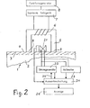
- Fig. 2 ein Blockschaltbild eines zweiten Ausführungsbeispiels der erfindungsgemäßen Vorrichtung, bei der das auszuwertende Signal mit Hilfe einer Wirbelstromspule gewonnen wird.
- Fig. L is a block diagram of a first embodiment of the device according to the invention, in which the signal to be evaluated is supplied by an inductive transducer and
- Fig. 2 is a block diagram of a second embodiment of the device according to the invention, in which the signal to be evaluated is obtained using an eddy current coil.
In Fig. 1 ist vergrößert und schematisch ein Prüfling 1 dargestellt, der aus einem ferromagnetischen Material besteht und auf einem verhältnismäßig weichen Grundgefüge 2 eine harte Deckschicht 3 aufweist. Die in Fig. 1 schematisch dargestellte erfindungsgemäße Vorrichtung gestattet es, die Dicke der Deckschicht 3 und somit die Einhärtetiefe zerstörungsfrei zu bestimmen.In Fig. 1, a
Dazu ist auf die Oberfläche 4 des Prüflings 1 ein Magnetisierungsjoch 5 aufgesetzt, dessen schematisch durch einige Windungen dargestellte Erregerspule 6 mit den Ausgängen eines bipolaren Netzgerätes 7 verbunden ist. Das bipolare Netzgerät 7 wird mit Hilfe eines Funktionsgenerators 8 gesteuert, so daß das bipolare Netzgerät 7 beispielsweise einen sägezahnförmigen Strom in die Erregerspule 6 einprägt. Dadurch entsteht an den Enden 9 des Magnetisierungsjoches 5 abwechselnd ein Nordpol und ein Südpol und in dem über den Prüfling geschlossenen Magnetkreis ein magnetischer Fluß, durch den die Hysteresekurve des Prüflings 1 mit der Deckschicht 3 und dem Grundgefüge 2 durchgesteuert wird. Die Frequenz der Durchsteuerung liegt zwischen 0,1 und 1000 Hz, vorzugsweise zwischen etwa 20 und 200 Hz.For this purpose, a
Bei der Durchsteuerung der Hysteresekurve werden die Blochwände des Prüflings 1 durch Wechselwirkung mit Gitterdefekten und untereinander in Potentialmulden festgehalten. Durch das vom Magnetisierungsjoch 5 erzeugte Magnetfeld werden Kräfte auf die Blochwände ausgeübt und sobald ein Potentialberg überschritten ist, bewegt sich die betreffende Blochwand, bis sie an einem anderen Potentialberg hängenbleibt. Diese impulsartige Magnetisierungsänderung induziert ein Spektrum von Mikro-Wirbelströmen, die an der Oberfläche 4 des Prüflings 1 gemessen werden können. Bei genauerer Auflösung der Hysteresekurve zeigt sich, daß diese eigentlich sägezahnförmig verläuft und daß der Prüfling 1 nicht nur kontinuierlich magnetisiert wird, sondern daß sprunghafte Magnetisierungsänderungen auftreten. Die sprunghaften Blochwandbawegungen, die ein Barkhausenereignis darstellen, erzeugen somit ein kontinuierliches Spektrum von Wirbelströmen, dessen einzelne Frequenzkomponenten auf ihrem Laufweg zur Oberfläche 4 infolge der frequenzabhängigen Wirbelstromdämpfung unterschiedlich abgeschwächt werden. Dabei gilt für die frequenzabhängige Wirbelstromdämpfung d:
Das sowohl von dem Grundgefüge 2 als auch von der Deckschicht 3 bei der Durchsteuerung der Hysteresekurve ausgehende Barkhausenrauschen wird mit Hilfe eines induktiven Aufnehmers 10 erfaßt, der gegen die Oberfläche 4 des Prüflings 1 anliegt. Der induktive Aufnehmer 10 kann als Luftspule oder als Tonbandkopf ausgebildet sein und ist über eine abgeschirmte Leitung 11 mit einem Vorverstärker 12 verbunden, dessen Verstärkung beispielsweise 60 dB betragen kann.The Barkhausen noise emanating both from the
Das am Ausgang des Vorverstärkers 12 zur Verfügung stehende breitbandige Spektrum des Barkhausenrauschens gelangt über ein Filter 13 zu einem Gleichrichter 14, so daß am Gleichrichterausgang 15 eine veränderliche Gleichspannung auftritt, deren Amplitude dem vom Filter 13 durchgelassenen Rauschsignal entspricht.The broadband spectrum of Barkhausen noise available at the output of the preamplifier 12 passes through a
Das im Prüfling 1 erzeugte Barkhausenrauschen verändert während des Durchsteuerns der Hysteresekurve seine Amplitude. Da bei der Bewegung einer 180° Blochwand die Magnetisierungsänderung bezogen auf den Weg maximal ist, tritt das Maximum des Rauschens bei Eisenwerkstoffen dort auf, wo bevorzugt 180° Blochwände bewegt werden. Dies ist bei der Koerzitivfeldstärke Hc der Fall. Die Koerzitivfeldstärke Hc ist mit der Härte korreliert, so daß die beim maximalen Rauschen vorhandene Tangentialfeldstärke an der Oberfläche 4 des Prüflings 1 ein Maß für die im Wechselwirkungsvolumen der Meßanordnung vorhandene Härte ist.The Barkhausen noise generated in the device under
Zur Erfassung der Tangentialfeldstärke ist zwischen den Magnetpolen des Magnetisierungsjoches 5 in der Nähe des induktiven Aufnehmers 10 ein H-Feldmesser 16 angeordnet, der beispielsweise als Hallsonde realisiert sein kann. Der H-Feldmesser 16 ist ebenfalls wie der Gleichrichterausgang 15 elektrisch mit einer Auswerteschaltung 17 verbunden, die u.a. ermittelt, bei welcher vom H-Feldmesser 16 gemessenen Tangentialfeldstärke ein Rauschmaximum auftritt. Bei einem homogenen Prüfling ergibt sich lediglich ein Rauschmaximum bei einer bestimmten positiven Tangentialfeldstärke und ein entsprechendes Rauschmaximum bei der dem Betrag nach gleichen, aber der Richtung nach entgegengesetzten Tangentialfeldstärke. Diese die Koerzitivfeldstärke Hc darstellenden Tangentialfeldstärken können über eine Anzeigevorrichtung 18 von der Auswerteschaltung 17 ausgegeben werden.To detect the tangential field strength, an H-
Erfindungsgemäß ist das Filter 13 über eine Steuerleitung 19 durch die Auswerteschaltung 17 in seiner Durchlaßfrequenz verstellbar. Das Filter 13 kann als Bandfilter oder als Hochpaß ausgebildet sein. Über die Steuerleitung 19 ist eine Verstellung derart möglich, daß bei einem Bandfilter die Mittenfrequenz zwischen etwa 1 kHz und 500 kHz oder daß bei einem Hochpaß die Grenzfrequenz zwischen etwa 1 kHz und 500 kHz verstellt werden kann. Auf diese Weise kann die dem Gleichrichter 14 zugeführte Analysierfrequenz zu hohen oder niedrigeren Frequenzen verschoben werden. Infolge der frequenzabhängigen Wirbelstromdämpfung gelangen die hochfrequenten Anteile des Barkhausenrauschens des Grundgefüges 2 nur erheblich abgeschwächt zur Oberfläche 4. Die hochfrequenten Anteile des Barkhausenrauschens der Deckschicht 3 jedoch werden wegen der unmittelbaren Nähe zur Oberfläche 4 nur wenig abgeschwächt. Treten somit bei einer vorgegebenen Einstellung der Mittenfrequenz oder der Grenzfrequenz des Filters 13 im positiven Bereich und im negativen Bereich der Tangentialfeldstärke 2 Rauschmaxima auf, von denen das einer absolut kleineren Tangentialfeldstärke zugeordnete von dem weicheren Grundgefüge 2 und das der einer absolut größeren Tangentialfeldstärke zugeordnete von der härteren Deckschicht 3 verursacht ist, so kann durch ein Erhöhen der Filterfrequenz erreicht werden, daß das dem Grundgefüge 2 zugeordnete Rauschmaximum mehr und mehr unterdrückt wird, weil die hohen Frequenzen des Barkhausenrauschens auf ihrem verhältnismäßig langen Weg zur Oberfläche 4 stärker unterdrückt werden als die entsprechenden Frequenzen des auf die Deckschicht 3 zurückzuführenden Barkhausenrauschens.According to the invention, the
Zur Bestimmung der Härtetiefe, z.B. der Einhärtetiefe, wird über den durch die Auswerteschaltung 17, das Filter 13 und den Gleichrichter 14 geschlossenen Regelkreis die Filterfrequenz so lange erhöht, bis das dem weicheren Grundgefüge 2 zugeordnete Barkhausenrauschen nicht mehr festgestellt werden kann. Die dann von der Auswerteschaltung 17 über die Steuerleitung 19 bestimmte Frequenz des Filters 13 ist ein Maß für den Abstand des Grundgefüges 2 von der Oberfläche 4 und damit ein Maß für die Einhärtetiefe und die Dicke der Deckschicht 3. Je größer die Einhärtetiefe und je dicker die Deckschicht 3 ist, umso mehr verschwinden die hochfrequenten Anteile im Barkhausenrauschen des Grundgefüges 2 und umso niedriger ist die von der Auswerteschaltung 17 bestimmte Grenzfrequenz oder Mittenfrequenz des Filters 13, wenn das Rauschmaximum des Barkhausenrauschens des Grundgefüges 2 gerade unterdrückt ist.To determine the depth of hardness, e.g. the hardening depth, the filter frequency is increased via the control circuit closed by the
Die Auswerteschaltung 17 berechnet die der Grenzfrequenz oder Mittenfrequenz des Filters 13 zugeordnete Analysiertiefe aufgrund der oben erwähnten frequenzabhängigen Wirbelstromdämpfung und zeigt das Ergebnis auf der Anzeigevorrichtung 18 an.The
Die in Fig. 1 gezeigte Vorrichtung gestattet es somit, einerseits die Härtetiefe der Deckschicht 3 zu bestimmen, indem eine Frequenz und ein zugehöriger Dämpfungsweg bestimmt werden. Außerdem gestattet es die in Fig. 1 gezeigte Vorrichtung, die Koerzitivfeldstärke des Grundgefüges 2 aufgrund der Lage des ersten Rauschmaximums bezüglich der Tangentialfeldstärke und die Koerzitivfeldstärke der Deckschicht 3 aufgrund der Lage des zweiten Rauschmaximums bezüglich- der Tangentialfeldstärke zu bestimmen und über die Anzeigevorrichtung 18 wiederzugeben.The device shown in FIG. 1 thus makes it possible, on the one hand, to determine the depth of hardness of the
In Fig. 2 ist ein weiteres Ausführungsbeispiel der Erfindung dargestellt, das die Messung der Härtetiefe ebenfalls gestattet.FIG. 2 shows a further exemplary embodiment of the invention, which also allows the depth of hardness to be measured.
Die in Fig. 2 dargestellten Teile, die mit den in Fig. 1 dargestellten Teilen übereinstimmen, sind mit den gleichen Bezugszeichen versehen. Insbesondere erkennt man in Fig. 2 den Prüfling 1 mit dem Grundgefüge 2, dem Deckgefüge 3 und der Oberfläche 4, auf der das Magnetisierungsjoch 5 mit der Erregerspule 6 aufgesetzt ist, die über ein bipolares Netzgerät 7 erregt wird, dessen Ausgangsstrom bezüglich der Frequenz und der Form durch den Funktionsgenerator 8 bestimmt ist. Die Frequenz des Funktionsgenerators 8 und damit die Frequenz der Durchsteuerung der Hysteresekurve liegt zwischen etwa 0,1 und 1000 Hz. Vorzugsweise beträgt sie etwa 20 bis 200 Hz.The parts shown in Fig. 2, which correspond to the parts shown in Fig. 1, are given the same reference numerals. In particular, one can see in FIG. 2 the device under
Wie bei dem Ausführungsbeispiel gemäß Fig. l, ist zwischen den Enden 9 des Magnetisierungsjoches 5 ein H-Feldmesser 16 angeordnet, durch den die jeweilige Tangentialfeldstärke während des Durchsteuerns der Hysteresekurve gemessen wird. Während des Durchsteuerns der Hysteresekurve verändert sich die Überlagerungspermeabilität. Sie hat in der Umgebung der Koerzitivfeldstärke Hc ein Maximum.As in the exemplary embodiment according to FIG. 1, an H-
Zur Bestimmung der Überlagerungspermeabilität und damit der Koerzitivfeldstärke Hc sowie der Härte, verfügt die in Fig. 2 dargestellte Vorrichtung über eine Wirbelstromspule 21, die als Pfannkuchenspule oder als Ferritjoch ausgebildet sein kann und durch einen Stromgenerator 22 mit einem Wechselstrom versorgt wird, dessen Frequenz wesentlich höher ist als die Frequenz, mit der die Hysteresekurve durchgesteuert wird. Beim Überlagern des langsam durchgesteuerten Magnetfelds des Magnetisierungsjoches 5 durch das höherfrequente Magnetfeld der Wirbelstromspule 21 niedrigerer Amplitude, werden auf der Hysteresekurve lanzettförmige innere Schleifen durchgesteuert. Die dem höherfrequenten in die Wirbelstromspule 21 eingeprägten Strom zugeordnete Spannung wird mit einem Voltmeter 23 gemssen. Auf diese Weise kann die Impedanz der Wirbelstromspule 21 aus dem jeweiligen Strom und der jeweiligen Spannung ermittelt werden. Die jeweils ermittelte Impedanz ist eine Funktion der Überlagerungspermeabilität und ist daher bei der Koerzitivfeldstärke am größten. Aus diesem Grund ergibt sich ein Maximum der Impedanz der Wirbelstromspule 21, wenn die vom H-Feldmesser erfaßte Tangentialfeldstärke der Koerzitivfeldstärke entspricht.To determine the superimposition permeability and thus the coercive force H c and the hardness, the device shown in FIG. 2 has an eddy
Die Auswerteschaltung 24 bestimmt aus den vom Stromgenerator 22 eingeprägten Stromwerten und den vom Voltmeter 23 gemessenen Spannungswerten die jeweilige Impedanz der Wirbelstromspule 21 und gestattet die Bestimmung und die Anzeige derjenigen Tangentialfeldstärke, bei der die gemessene bzw. errechnete Impedanz maximal ist.The evaluation circuit 24 determines the respective impedance of the
Die Prüffrequenz des Stromgenerators 22 kann über eine Steuerleitung 25 von der Auswerteschaltung 24 zwischen 1 kHz und 100 MHz, vorzugsweise zwischen 20 kHz und 2 MHz verstellt werden. In Abhängigkeit von der jeweiligen Stromgeneratorfrequenz ergibt sich für das Feld der Wirbelstromspule 21 eine Eindringtiefe 0 gemäß der Gleichung
Über die Steuerleitung 25 ist es der Auswerteschaltung 24 daher möglich, über eine Änderung der Prüffrequenz des Stromgenerators 22 die Eindringtiefe des Feldes der Wirbelstromspule 21 festzulegen.Via the
Bei niedrigen Prüffrequenzen für den Stromgenerator 22 ergibt sich aufgrund der oben erwähnten Standardeindringtiefe eine große Analysiertiefe für die Impedanzmessung und damit die Koerzitivfeldstärke. Die Auswerteschaltung 24 ist so aufgebaut, daß sie während einer Tiefenprofilmessung, bei der die Hysteresekurve mehrfach durchgesteuert wird, die Prüffrequenz des Stromgenerators 22 nach jeder durchgesteuerten Hysteresekurve erhöht. Dadurch verringert sich laufend die Analysiertiefe und das Wechselwirkungsvolumen. Bei sehr niedrigen Prüffrequenzen und hohen Analysiertiefen verschiebt sich die Lage des Maximums der von der Auswerteschaltung 24 berechneten Impedanz bezüglich der vom H-Feldmesser jeweils erfaßten Tangentialfeldstärke nur unwesentlich. Im Verlauf der Erhöhungen der Prüffrequenz für jede nachfolgende Durchsteuerung der Hysteresekurve wird bei einer Eindringtiefe in der Größenordnung der Einhärtetiefe ein Punkt erreicht, bei dem das Impedanzmaximum während des Durchsteuerns der Hysteresekurve in Bezug auf die Tangentialfeldstärke schneller zu größeren Feldstärkewerten wandert. Bei weiteren Erhöhungen der Prüffrequenz während nachfolgender Hysteresekurven verschiebt sich die Lage des Impedanzmaximums erneut geringfügiger, wenn die Eindringtiefe des Feldes der Wirbelstromspule 21 geringer als die Dicke der Deckschicht 3 ist.At low test frequencies for the
Zur Bestimmung der Einhärtetiefe ermittelt die Auswerteschaltung 24 somit für alle Hysteresekurven die Tangentialfeldstärken, bei denen die Impedanz der Wirbelstromspule 21 maximal ist. Durch einen Vergleich der Lageveränderungen der Impedanzmaxima bei vorgegebenen Prüffrequenzänderungen bestimmt die Auswerteschaltung diejenige Prüffrequenz, bei der eine Frequenzänderung eine maximale Lageveränderung des Impedanzmaximums bezüglich der absoluten Tangentialfeldstärke auslöst. Diese Prüffrequenz ist ein Maß für die Einhärtetiefe und die Dicke der Deckschicht 3.To determine the hardening depth, the evaluation circuit 24 thus determines the tangential field strengths for all hysteresis curves at which the impedance of the
Die Auswerteschaltung 24 gestattet unter Berücksichtigung der Überlagerungspermeabilität und der beispielsweise konstant angenommenen Leitfähigkeit eine Berechnung der der in der oben beschriebenen Weise ermittelten Prüffrequenz zugeordneten Eindringtiefe. Diese Eindringtiefe kann unmittelbar oder nach Korrektur durch eine Konstante und/oder einen Korrekturfaktor auf einer Anzeigevorrichtung 26 dargestellt werden.The evaluation circuit 24, taking into account the superimposition permeability and the conductivity, for example, assumed to be constant, allows a calculation of the penetration depth assigned to the test frequency determined in the manner described above. This depth of penetration can be displayed on a
Das in Fig. 2 dargestellt Ausführungsbeispiel der Erfindung gestattet somit die Bestimmung einer Prüffrequenz und daraus eine Ableitung der Einhärtetiefe.The exemplary embodiment of the invention shown in FIG. 2 thus allows a test frequency to be determined and the hardness depth to be derived therefrom.
Claims (7)
Priority Applications (1)
| Application Number | Priority Date | Filing Date | Title |
|---|---|---|---|
| AT83106710T ATE16532T1 (en) | 1982-07-09 | 1983-07-08 | DEVICE FOR NON-DESTRUCTIVE MEASUREMENT OF THE HARDENING DEPTH OF MATERIALS. |
Applications Claiming Priority (2)
| Application Number | Priority Date | Filing Date | Title |
|---|---|---|---|
| DE3225743 | 1982-07-09 | ||
| DE3225743 | 1982-07-09 |
Publications (2)
| Publication Number | Publication Date |
|---|---|
| EP0100009A1 true EP0100009A1 (en) | 1984-02-08 |
| EP0100009B1 EP0100009B1 (en) | 1985-11-13 |
Family
ID=6168059
Family Applications (1)
| Application Number | Title | Priority Date | Filing Date |
|---|---|---|---|
| EP83106710A Expired EP0100009B1 (en) | 1982-07-09 | 1983-07-08 | Device for non destructive measuring of the case hardening depth of a material |
Country Status (3)
| Country | Link |
|---|---|
| EP (1) | EP0100009B1 (en) |
| AT (1) | ATE16532T1 (en) |
| DE (1) | DE3361224D1 (en) |
Cited By (17)
| Publication number | Priority date | Publication date | Assignee | Title |
|---|---|---|---|---|
| WO1985003577A1 (en) * | 1984-02-07 | 1985-08-15 | Wolfgang Stengel | Non destructive test of materials for ferromagnetic substances |
| EP0287873A2 (en) * | 1987-04-16 | 1988-10-26 | Siemens Aktiengesellschaft | Process for measuring and exactly localizing the strain in hardened areas of structural elements |
| WO1988010420A2 (en) * | 1987-06-27 | 1988-12-29 | Stiftung Institut für Werkstofftechnik | Process for determining the edge layer condition of objects |
| EP0531042A2 (en) * | 1991-09-04 | 1993-03-10 | Iowa State University Research Foundation, Inc. | System and method for evaluation of surface characteristics of a magnetic material |
| EP0595117A1 (en) * | 1992-10-21 | 1994-05-04 | Fraunhofer-Gesellschaft Zur Förderung Der Angewandten Forschung E.V. | Device for spatially resolved and non-destructive inspection of magnetic parameters |
| WO1996010744A1 (en) * | 1993-09-30 | 1996-04-11 | Pro Innovatio Forschungszentrum Für Hochtechnologie Und Industrielle Anwendung Gmbh | Process and arrangement for selectively obtaining suitable values for the continuous localised monitoring of the surface parameters |
| FR2743148A1 (en) * | 1995-12-29 | 1997-07-04 | Framatome Sa | DEVICE AND METHOD FOR MONITORING TUBES BY EDGE CURRENT |
| EP1767932A1 (en) * | 2005-09-23 | 2007-03-28 | Fraunhofer-Gesellschaft zur Förderung der angewandten Forschung e.V. | Device and method for non-destructive testing of components |
| US8436608B2 (en) | 2009-09-21 | 2013-05-07 | General Electric Company | Eddy current inspection system and method |
| WO2013149776A1 (en) | 2012-04-05 | 2013-10-10 | Zf Friedrichshafen Ag | Method for inspecting a component on the basis of barkhausen noises |
| WO2013149775A1 (en) | 2012-04-05 | 2013-10-10 | Zf Friedrichshafen Ag | Method for calibrating a measuring device for inspecting surfaces on the basis of barkhausen noises for a specified component geometry |
| EP2706351A3 (en) * | 2012-09-07 | 2014-04-02 | Fraunhofer-ges. zur Förderung der Angewandten Forschung E.V. | Method, device and use of the device for non-destructive quantitative determination of layer thicknesses of a body with layers |
| WO2015081352A1 (en) * | 2013-12-02 | 2015-06-11 | Ceratizit Austria Gesellschaft M.B.H. | Method for hard metal body characterization |
| WO2016085382A1 (en) * | 2014-11-28 | 2016-06-02 | Scania Cv Ab | A method of calibrating an evaluation arrangement for sensing magnetic barkhausen noise. |
| WO2016096661A1 (en) * | 2014-12-17 | 2016-06-23 | Compagnie Generale Des Etablissements Michelin | Method for measuring the thickness of a layer of rubber-like material |
| EP3056897A1 (en) | 2015-02-13 | 2016-08-17 | Pentacon Gmbh Foto- Und Feinwerktechnik | Method and device for testing ferromagnetic workpieces for inhomogeneities, in particular for cracks and/or overheating while grinding |
| CN109991308A (en) * | 2019-03-18 | 2019-07-09 | 北京工业大学 | Micro- magnetic lossless audio coding system of Thin Strip Steel comprehensive mechanical property |
Families Citing this family (7)
| Publication number | Priority date | Publication date | Assignee | Title |
|---|---|---|---|---|
| US8797023B2 (en) * | 2011-03-07 | 2014-08-05 | Toyota Jidosha Kabushiki Kaisha | Coercive force specifying apparatus |
| DE102014114226A1 (en) | 2014-09-30 | 2016-03-31 | Rohmann Gmbh | Eddy current test with pulse magnetization |
| CN105548924A (en) * | 2016-01-28 | 2016-05-04 | 中国特种设备检测研究院 | Magnetic Barkhausen and magnetic parameter sensor and measurement method of magnetic Barkhausen and magnetic parameter |
| CN105717191A (en) * | 2016-01-28 | 2016-06-29 | 中国特种设备检测研究院 | Detection method and device for magnetic Barkhausen noise signal and magnetic parameters |
| CN105866234B (en) * | 2016-03-23 | 2019-09-06 | 重庆大学 | The ferromagnetic material nondestructive detecting instrument and method that current vortex and Barkhausen blend |
| CN105911489B (en) * | 2016-04-10 | 2018-11-02 | 北京工业大学 | The multi-functional micro- magnetic signal synchronization detecting method of common source dual-frequency excitation formula |
| CN105784833A (en) * | 2016-05-17 | 2016-07-20 | 中国特种设备检测研究院 | Multi-magnetic-parameter sensor |
Citations (2)
| Publication number | Priority date | Publication date | Assignee | Title |
|---|---|---|---|---|
| DE2837733A1 (en) * | 1978-08-30 | 1980-03-27 | Fraunhofer Ges Forschung | Non-destructive materials states testing - involves measuring acoustic barkhausen effects induced in sample by magnetic-barkhausen effect |
| DE3037932A1 (en) * | 1980-10-08 | 1982-04-15 | Fraunhofer-Gesellschaft zur Förderung der angewandten Forschung e.V., 8000 München | Measuring coercive field strengths on extensive surfaces - by quasi-stationary and dynamic cycling through hysteresis curve |
-
1983
- 1983-07-08 EP EP83106710A patent/EP0100009B1/en not_active Expired
- 1983-07-08 AT AT83106710T patent/ATE16532T1/en not_active IP Right Cessation
- 1983-07-08 DE DE8383106710T patent/DE3361224D1/en not_active Expired
Patent Citations (2)
| Publication number | Priority date | Publication date | Assignee | Title |
|---|---|---|---|---|
| DE2837733A1 (en) * | 1978-08-30 | 1980-03-27 | Fraunhofer Ges Forschung | Non-destructive materials states testing - involves measuring acoustic barkhausen effects induced in sample by magnetic-barkhausen effect |
| DE3037932A1 (en) * | 1980-10-08 | 1982-04-15 | Fraunhofer-Gesellschaft zur Förderung der angewandten Forschung e.V., 8000 München | Measuring coercive field strengths on extensive surfaces - by quasi-stationary and dynamic cycling through hysteresis curve |
Non-Patent Citations (1)
| Title |
|---|
| JOURNAL PHYSICS E: SCIENTIFIC INSTRUMENTS, Band 11, 1978, London R. TER STEGE et al. "Equipment for the investigation of statistical properties of the Barkhausen effect", Seiten 791-793 * |
Cited By (28)
| Publication number | Priority date | Publication date | Assignee | Title |
|---|---|---|---|---|
| WO1985003577A1 (en) * | 1984-02-07 | 1985-08-15 | Wolfgang Stengel | Non destructive test of materials for ferromagnetic substances |
| EP0287873A2 (en) * | 1987-04-16 | 1988-10-26 | Siemens Aktiengesellschaft | Process for measuring and exactly localizing the strain in hardened areas of structural elements |
| US4881030A (en) * | 1987-04-16 | 1989-11-14 | Siemens Aktinegesellschaft | Method and apparatus for measuring and precisely locating internal tensile stresses in hardened regions of components by measuring coercive field strength and barkhausen noise amplitude |
| EP0287873A3 (en) * | 1987-04-16 | 1991-02-27 | Siemens Aktiengesellschaft | Process for measuring and exactly localizing the strain in hardened areas of structural elements |
| WO1988010420A2 (en) * | 1987-06-27 | 1988-12-29 | Stiftung Institut für Werkstofftechnik | Process for determining the edge layer condition of objects |
| WO1988010420A3 (en) * | 1987-06-27 | 1989-01-12 | Inst Werkstofftech Stiftung | Process for determining the edge layer condition of objects |
| EP0531042A2 (en) * | 1991-09-04 | 1993-03-10 | Iowa State University Research Foundation, Inc. | System and method for evaluation of surface characteristics of a magnetic material |
| EP0531042A3 (en) * | 1991-09-04 | 1994-03-23 | Univ Iowa State Res Found Inc | |
| EP0595117A1 (en) * | 1992-10-21 | 1994-05-04 | Fraunhofer-Gesellschaft Zur Förderung Der Angewandten Forschung E.V. | Device for spatially resolved and non-destructive inspection of magnetic parameters |
| WO1996010744A1 (en) * | 1993-09-30 | 1996-04-11 | Pro Innovatio Forschungszentrum Für Hochtechnologie Und Industrielle Anwendung Gmbh | Process and arrangement for selectively obtaining suitable values for the continuous localised monitoring of the surface parameters |
| FR2743148A1 (en) * | 1995-12-29 | 1997-07-04 | Framatome Sa | DEVICE AND METHOD FOR MONITORING TUBES BY EDGE CURRENT |
| WO1997024611A1 (en) * | 1995-12-29 | 1997-07-10 | Framatome | Device and method for eddy current testing of tubes |
| EP1767932A1 (en) * | 2005-09-23 | 2007-03-28 | Fraunhofer-Gesellschaft zur Förderung der angewandten Forschung e.V. | Device and method for non-destructive testing of components |
| US8436608B2 (en) | 2009-09-21 | 2013-05-07 | General Electric Company | Eddy current inspection system and method |
| WO2013149776A1 (en) | 2012-04-05 | 2013-10-10 | Zf Friedrichshafen Ag | Method for inspecting a component on the basis of barkhausen noises |
| US9383339B2 (en) | 2012-04-05 | 2016-07-05 | Zf Friedrichshafen Ag | Method for inspecting a component on the basis of Barkhausen noises |
| DE102012205677A1 (en) | 2012-04-05 | 2013-10-10 | Zf Friedrichshafen Ag | Method for testing a component based on Barkhausen noise |
| DE102012205676A1 (en) | 2012-04-05 | 2013-10-10 | Zf Friedrichshafen Ag | A method of calibrating a surface inspection measuring device based on Barkhausen noise for a predetermined component geometry |
| WO2013149775A1 (en) | 2012-04-05 | 2013-10-10 | Zf Friedrichshafen Ag | Method for calibrating a measuring device for inspecting surfaces on the basis of barkhausen noises for a specified component geometry |
| US9404989B2 (en) | 2012-04-05 | 2016-08-02 | Zf Friedrichshafen Ag | Method for calibrating a measuring device for inspecting surfaces on the basis of Barkhausen noises for a specified component geometry |
| EP2706351A3 (en) * | 2012-09-07 | 2014-04-02 | Fraunhofer-ges. zur Förderung der Angewandten Forschung E.V. | Method, device and use of the device for non-destructive quantitative determination of layer thicknesses of a body with layers |
| WO2015081352A1 (en) * | 2013-12-02 | 2015-06-11 | Ceratizit Austria Gesellschaft M.B.H. | Method for hard metal body characterization |
| WO2016085382A1 (en) * | 2014-11-28 | 2016-06-02 | Scania Cv Ab | A method of calibrating an evaluation arrangement for sensing magnetic barkhausen noise. |
| WO2016096661A1 (en) * | 2014-12-17 | 2016-06-23 | Compagnie Generale Des Etablissements Michelin | Method for measuring the thickness of a layer of rubber-like material |
| FR3030717A1 (en) * | 2014-12-17 | 2016-06-24 | Michelin & Cie | METHOD FOR MEASURING THE THICKNESS OF A LAYER OF RUBBER MATERIAL |
| US10190863B2 (en) | 2014-12-17 | 2019-01-29 | Compagnie Generale Des Etablissements Michelin | Method for measuring the thickness of a layer of rubber-like material |
| EP3056897A1 (en) | 2015-02-13 | 2016-08-17 | Pentacon Gmbh Foto- Und Feinwerktechnik | Method and device for testing ferromagnetic workpieces for inhomogeneities, in particular for cracks and/or overheating while grinding |
| CN109991308A (en) * | 2019-03-18 | 2019-07-09 | 北京工业大学 | Micro- magnetic lossless audio coding system of Thin Strip Steel comprehensive mechanical property |
Also Published As
| Publication number | Publication date |
|---|---|
| DE3361224D1 (en) | 1985-12-19 |
| EP0100009B1 (en) | 1985-11-13 |
| ATE16532T1 (en) | 1985-11-15 |
Similar Documents
| Publication | Publication Date | Title |
|---|---|---|
| EP0100009B1 (en) | Device for non destructive measuring of the case hardening depth of a material | |
| EP1769239B1 (en) | Method for testing pipes in a non-destructive manner | |
| DE3813739C2 (en) | ||
| DE3930939C2 (en) | ||
| DE2928899C2 (en) | Device for determining the size and direction of the lateral deviation of a test head from the center line of a weld seam | |
| DE1473696B2 (en) | DEVICE FOR NON-DESTRUCTIVE MATERIAL TESTING | |
| DE19529630A1 (en) | Electromagnetic induction tester | |
| EP0220457B1 (en) | Method and apparatus for investigating ferromagnetic objects deposited in non-magnetic materials | |
| DE10000845B4 (en) | Method and device for non-contact flatness measurement of metal strips made of ferromagnetic materials | |
| DE10026313A1 (en) | Defect detection method for elongated ferromagnetic object, e.g. steel wire cable, uses magnetization and detection of magnetic field parameters at spaced points | |
| DE10045715A1 (en) | Method and device for testing a workpiece using eddy currents | |
| DE3631571C2 (en) | ||
| EP2056104B1 (en) | Method for determining geometrical characteristics of an anomaly in a test object and measuring apparatus for carrying out the method | |
| EP0595117B1 (en) | Device for spatially resolved and non-destructive inspection of magnetic parameters | |
| DE3537129C2 (en) | Method and device for non-destructive material testing, especially for thickness determination | |
| DE3037932A1 (en) | Measuring coercive field strengths on extensive surfaces - by quasi-stationary and dynamic cycling through hysteresis curve | |
| DE19726513C2 (en) | Device and method for eddy current testing | |
| DE19638776A1 (en) | Process for the non-destructive testing of a test object with a weld seam made of magnetizable material | |
| DE102013209774B4 (en) | Test method and test device for eddy current testing with premagnetization | |
| DE102018130090B4 (en) | Method for determining microstructure variations in a sample and analysis device | |
| DE4325767A1 (en) | Layer thickness measuring device | |
| AT390522B (en) | Arrangement for measuring magnetic characteristics | |
| DE3120522C2 (en) | Procedure for the determination of material properties | |
| DE4215358A1 (en) | Process for the non-destructive testing of steel reinforcements in buildings | |
| AT355838B (en) | METHOD FOR EXAMINING THE VOLTAGE CONDITION OF A BODY CONSISTING OF FERROMAGNETIC MATERIAL |
Legal Events
| Date | Code | Title | Description |
|---|---|---|---|
| PUAI | Public reference made under article 153(3) epc to a published international application that has entered the european phase |
Free format text: ORIGINAL CODE: 0009012 |
|
| AK | Designated contracting states |
Designated state(s): AT BE CH DE FR GB IT LI NL SE |
|
| 17P | Request for examination filed |
Effective date: 19840323 |
|
| ITF | It: translation for a ep patent filed |
Owner name: BUGNION S.P.A. |
|
| GRAA | (expected) grant |
Free format text: ORIGINAL CODE: 0009210 |
|
| AK | Designated contracting states |
Designated state(s): AT BE CH DE FR GB IT LI NL SE |
|
| REF | Corresponds to: |
Ref document number: 16532 Country of ref document: AT Date of ref document: 19851115 Kind code of ref document: T |
|
| REF | Corresponds to: |
Ref document number: 3361224 Country of ref document: DE Date of ref document: 19851219 |
|
| ET | Fr: translation filed | ||
| PLBE | No opposition filed within time limit |
Free format text: ORIGINAL CODE: 0009261 |
|
| STAA | Information on the status of an ep patent application or granted ep patent |
Free format text: STATUS: NO OPPOSITION FILED WITHIN TIME LIMIT |
|
| 26N | No opposition filed | ||
| PGFP | Annual fee paid to national office [announced via postgrant information from national office to epo] |
Ref country code: CH Payment date: 19920702 Year of fee payment: 10 |
|
| PGFP | Annual fee paid to national office [announced via postgrant information from national office to epo] |
Ref country code: BE Payment date: 19920730 Year of fee payment: 10 |
|
| ITTA | It: last paid annual fee | ||
| PGFP | Annual fee paid to national office [announced via postgrant information from national office to epo] |
Ref country code: NL Payment date: 19920731 Year of fee payment: 10 |
|
| PGFP | Annual fee paid to national office [announced via postgrant information from national office to epo] |
Ref country code: FR Payment date: 19930524 Year of fee payment: 11 |
|
| PGFP | Annual fee paid to national office [announced via postgrant information from national office to epo] |
Ref country code: SE Payment date: 19930611 Year of fee payment: 11 |
|
| PGFP | Annual fee paid to national office [announced via postgrant information from national office to epo] |
Ref country code: GB Payment date: 19930630 Year of fee payment: 11 |
|
| PG25 | Lapsed in a contracting state [announced via postgrant information from national office to epo] |
Ref country code: LI Effective date: 19930731 Ref country code: CH Effective date: 19930731 Ref country code: BE Effective date: 19930731 |
|
| PGFP | Annual fee paid to national office [announced via postgrant information from national office to epo] |
Ref country code: AT Payment date: 19930731 Year of fee payment: 11 |
|
| BERE | Be: lapsed |
Owner name: FRAUNHOFER G- ZUR FORDERUNG DER ANGEWANDTEN FORSC Effective date: 19930731 |
|
| PG25 | Lapsed in a contracting state [announced via postgrant information from national office to epo] |
Ref country code: NL Effective date: 19940201 |
|
| NLV4 | Nl: lapsed or anulled due to non-payment of the annual fee | ||
| REG | Reference to a national code |
Ref country code: CH Ref legal event code: PL |
|
| PG25 | Lapsed in a contracting state [announced via postgrant information from national office to epo] |
Ref country code: GB Effective date: 19940708 Ref country code: AT Effective date: 19940708 |
|
| PG25 | Lapsed in a contracting state [announced via postgrant information from national office to epo] |
Ref country code: SE Effective date: 19940709 |
|
| EUG | Se: european patent has lapsed |
Ref document number: 83106710.3 Effective date: 19950210 |
|
| GBPC | Gb: european patent ceased through non-payment of renewal fee |
Effective date: 19940708 |
|
| PG25 | Lapsed in a contracting state [announced via postgrant information from national office to epo] |
Ref country code: FR Effective date: 19950331 |
|
| EUG | Se: european patent has lapsed |
Ref document number: 83106710.3 |
|
| REG | Reference to a national code |
Ref country code: FR Ref legal event code: ST |
|
| PGFP | Annual fee paid to national office [announced via postgrant information from national office to epo] |
Ref country code: DE Payment date: 20000922 Year of fee payment: 18 |
|
| PG25 | Lapsed in a contracting state [announced via postgrant information from national office to epo] |
Ref country code: DE Free format text: LAPSE BECAUSE OF NON-PAYMENT OF DUE FEES Effective date: 20020501 |