EP0098528B1 - Récipient à ordures - Google Patents
Récipient à ordures Download PDFInfo
- Publication number
- EP0098528B1 EP0098528B1 EP83106367A EP83106367A EP0098528B1 EP 0098528 B1 EP0098528 B1 EP 0098528B1 EP 83106367 A EP83106367 A EP 83106367A EP 83106367 A EP83106367 A EP 83106367A EP 0098528 B1 EP0098528 B1 EP 0098528B1
- Authority
- EP
- European Patent Office
- Prior art keywords
- refuse receptacle
- guide
- receptacle according
- side wall
- receiving side
- Prior art date
- Legal status (The legal status is an assumption and is not a legal conclusion. Google has not performed a legal analysis and makes no representation as to the accuracy of the status listed.)
- Expired
Links
- 229920003023 plastic Polymers 0.000 claims description 8
- 239000004033 plastic Substances 0.000 claims description 8
- 239000000463 material Substances 0.000 claims description 3
- 241001441752 Philesturnus carunculatus Species 0.000 claims 2
- 230000001174 ascending effect Effects 0.000 claims 1
- 239000002699 waste material Substances 0.000 description 19
- 230000000694 effects Effects 0.000 description 4
- 238000013459 approach Methods 0.000 description 2
- 238000002347 injection Methods 0.000 description 2
- 239000007924 injection Substances 0.000 description 2
- 238000001746 injection moulding Methods 0.000 description 2
- 238000004519 manufacturing process Methods 0.000 description 2
- 238000000034 method Methods 0.000 description 2
- 239000000853 adhesive Substances 0.000 description 1
- 230000001070 adhesive effect Effects 0.000 description 1
- 238000006073 displacement reaction Methods 0.000 description 1
- 239000000945 filler Substances 0.000 description 1
- 229920000642 polymer Polymers 0.000 description 1
- 230000007704 transition Effects 0.000 description 1
- 238000003466 welding Methods 0.000 description 1
Images


Classifications
-
- B—PERFORMING OPERATIONS; TRANSPORTING
- B65—CONVEYING; PACKING; STORING; HANDLING THIN OR FILAMENTARY MATERIAL
- B65F—GATHERING OR REMOVAL OF DOMESTIC OR LIKE REFUSE
- B65F1/00—Refuse receptacles; Accessories therefor
- B65F1/02—Refuse receptacles; Accessories therefor without removable inserts
-
- B—PERFORMING OPERATIONS; TRANSPORTING
- B65—CONVEYING; PACKING; STORING; HANDLING THIN OR FILAMENTARY MATERIAL
- B65F—GATHERING OR REMOVAL OF DOMESTIC OR LIKE REFUSE
- B65F1/00—Refuse receptacles; Accessories therefor
- B65F1/12—Refuse receptacles; Accessories therefor with devices facilitating emptying
- B65F1/122—Features allowing the receptacle to be lifted and subsequently tipped by associated means on a vehicle
-
- B—PERFORMING OPERATIONS; TRANSPORTING
- B65—CONVEYING; PACKING; STORING; HANDLING THIN OR FILAMENTARY MATERIAL
- B65F—GATHERING OR REMOVAL OF DOMESTIC OR LIKE REFUSE
- B65F2220/00—Properties of refuse receptacles
- B65F2220/12—Properties of refuse receptacles nestable
Definitions
- the invention relates to a garbage container, in particular a plastic garbage container, with a garbage space bounded by a floor and side walls and edge profiles extending along the upper edges of the side walls, the edge profile on at least one side wall (receiving side wall) from below Has accessible cavity (receiving cavity) for the engagement of a gripper that has incisions and supporting edges extending between the incisions.
- the edge profiling on the receiving side wall is stiffened by ribs which are spaced such that they come to rest in the incisions of the gripper. Lateral alignment is also not achieved with this, since the width of the incisions in the gripper is a multiple of the rib thickness.
- the invention has for its object to design a garbage container of the type mentioned in such a way that it is aligned laterally on the gripper without tools on the garbage truck.
- guide surfaces and / or guide edges for cooperation with the gripper are arranged in the area below and / or within the receiving cavity in such a way that the side edges of the incisions of the gripper in the event of poor alignment of the refuse container along the gripper slide along the guide surfaces and / or the guide edges and align the container sideways.
- Guide surfaces arranged in the region below the cavity are particularly advantageous, since the alignment process begins with such guide surfaces before the gripper has penetrated into the receiving cavity. There is a great way for the alignment. An alignment effect can also be achieved if the gripper rail approaches the waste container horizontally, or the waste container is pushed horizontally onto the gripper rail. With an arrangement of the guide surfaces according to claim 3, the alignment is achieved with a horizontal relative displacement between the gripper and waste container. In one embodiment according to claim 4, the alignment takes place with vertical movement of the gripper relative to the waste container, while in the embodiment according to claim 5, alignment takes place both with horizontal relative movement and with vertical relative movement between gripper and waste container.
- the guide surfaces are preferably arranged symmetrically to the transverse center of the receiving side wall (claim 6). It is sufficient to accomplish the lateral alignment within a single cutout of the gripper. However, several sections can also be used for this.
- the connection of the guide surfaces via convexly curved surfaces according to claim 7 has the advantage that the connecting surface already has a guiding effect. This is particularly advantageous at the lower end of guide surfaces converging in the vertical direction. End faces according to claims 8 and 9 are advantageous for the appearance of the garbage container. With the measure of claim 9 you avoid protruding parts over the upper edge of the container and still use the largest possible path for centering.
- Base areas according to claim 10 have the advantage that after the lateral alignment has taken place, there is a stable lateral contact within the incisions.
- the structural design with which the guide surfaces and / or the guide edges are formed also depends heavily on the manufacturing process by which the waste container is manufactured.
- a waste container made of plastic which is produced by injection molding
- Arbitrarily shaped guide walls that is to say also walls converging in the vertical direction, can be produced relatively easily in the injection molding process in a design according to claim 17.
- a niche must then be accepted in the garbage room, which is generally not desirable there.
- Such a niche can be avoided if, according to claim 18, a separately produced filler body is inserted into the mold and overmoulded, or also in that, according to claim 19, a separately produced guide body is used which is fused to the waste container. A particularly good connection is obtained with the means of claim 20.
- Another possibility is to use a separately produced guide body which is placed on the waste container (claims 21 and 22).
- the invention is possible in principle with straight and curved receiving cavities.
- Straight receiving cavities according to claim 23 are customary.
- the invention is explained using the example of garbage containers which are designed as plastic injection molded parts.
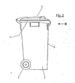
- the garbage container consists essentially of a box-shaped lower part 1 of approximately square horizontal cross section, which contains the garbage room, a hinged lid 2 closing the garbage room and a trolley 3, which consists of two rollers.
- an edge profile 4 along the upper edge of the lower part 1 extends an edge profile 4, with which a suitable edge for the placement of the refuse container when it is automatically emptied is formed; at the same time, the edge profiling stiffens the opening of the lower part 1.
- the container When the garbage container is automatically emptied with a garbage collecting vehicle, the container is received at the upper edge of its side wall 5, which is therefore referred to as the receiving side wall.
- a gripper which is usually designed as a straight rail, engages under the edge profile 4, which extends along the upper edge of the receiving side wall.
- the gripper has horizontal supporting edges and vertical incisions. It is important that the garbage container is aligned relatively precisely on the gripper so that the upper opening of the container comes to rest securely on the corresponding filling opening of the garbage collection vehicle when it is tilted.
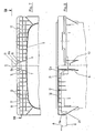
- a body, generally designated 6, is arranged on the receiving side wall 5 and is formed in one piece with the refuse container.
- the body 6 has base walls 7, 8 which are approximately at right angles to the receiving side wall 5.
- the base walls 7, 8 merge into guide walls 9, 10, which converge with increasing distance from the receiving side wall 5.
- the guide walls 9, 10 form guide surfaces 9a, 10a, which are arranged symmetrically with respect to the transverse center marked by the dash-dotted line 11 of a receiving cavity designated overall by 12.
- the guide walls 9, 10 are connected to one another via an end wall 13 which lies in the same plane as an end wall 14 of the receiving cavity 12.
- the walls of the projection 6 have lower end edges which run obliquely upwards.
- the end edges project into a straight line 15 in FIG. 5.
- the walls of the receiving cavity 12 are heavily ribbed in order to be supported by the supporting edges of the gripper to be sufficiently stable.
- the ribbing of the upper wall 16 consists of a system of longitudinal ribs 17, 18 and transverse ribs 19 crossing at right angles.
- the longitudinal rib 17 is pulled down at its ends (regions 17a and 17b). These rib areas form guide edges 20 and 21, which further contribute to the lateral alignment of the container relative to the gripper.
- the guide surfaces 9a and 10a converge only in the horizontal direction.
- the projection 6, which forms the guide surfaces, has a hollow 22 which is open at the bottom. This design enables the projection 6 to be produced in one piece with the lower container part 1 with a simple tool, since there are no undercuts.
- the alignment effect of the guide surfaces 9a and 10a occurs when there is a horizontal movement between the waste container and the gripper. In the area of the guide edges 20 and 21 (of course, corresponding guide edges are present to the right of the transverse center 11), a vertical relative movement between the gripper and the container has an aligning effect.
- the gripper G indicated by dash-dotted lines engages with corners of its cutouts A in the inside corners which exist between the horizontal part of the longitudinal rib 17 and the guide edges 20, 21. After the gripper G has penetrated into the receiving cavity 12, horizontal movements of the gripper relative to the waste container are in any case only very limited or even not possible at all.
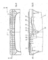
- a nose-shaped body 23 is formed on the receiving side wall 5 in the area below the receiving cavity 12.
- the body 23 has guide surfaces 24 and 25 which converge both in the vertical direction downwards and in the horizontal direction with increasing distance from the receiving side wall 5.
- the guide surfaces 24, 25 are connected via an end wall 26 which is again in the plane of FIG End wall 27 of the receiving cavity 12 is located.
- the guide surfaces are connected to one another by a convex surface 28.
- the guide surfaces 24, 25 merge into further guide surfaces 29, 30, which only converge in the horizontal direction.
- the body 23 is formed in one piece with the waste container, the wall 5 bulging outwards at the location of the body 23.
- the production is extremely simple. However, an inner wall that runs smoothly right up to the top must be dispensed with.
- the nose-like projection 23 acts due to the double inclination of the guide surfaces 24, 25, so to speak, both when the gripper is moved horizontally towards the wall 5 and when the gripper moves vertically relative to the container.
- guide edges 20 and 21 are provided in addition to the guide surfaces 24, 25.
- the disadvantage just mentioned that the inner wall of the container is not continuously smooth is avoided, although here too there is a guide projection 31 which has guide surfaces 32 and 33 which are both horizontal and converge vertically.
- the outer shape of the body 31 is of the same design as that of the nose-shaped projection 23 according to FIGS. 9 and 10; only the proportions are slightly different.
- the guide surfaces 32, 33 and the transition surfaces between these guide surfaces are formed here by an attached body 34.
- the body 34 is preferably also a plastic injection molded part.
- the attachment takes place in that the body is pushed onto ribs 35, 36 which are formed on the receiving side wall 5 of the container.
- the ribs 35, 36 have lateral projections 37 of a T-shaped cross section in order to make the contact surface with the body 34 even larger and thus to make the connection even more secure.
- the body 34 also engages in the receiving cavity 12 and also forms guide surfaces there. For additional protection against sliding of the body 34, an adhesive bond or a mechanical latching can be produced between the body and the ribs 35, 36.
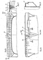
- the outer shape of the guide lug 38 is the same as in the embodiment according to FIGS. 11 to 14.
- the guide surfaces 39, 40 are formed here by the surface of a body 41, which was manufactured separately before the waste container was formed, but when the waste container was formed Garbage container was fused with this.
- the body 41 contains a plurality of parallel grooves 42 to 46. When the garbage container is formed, the plastic flows into the grooves 42 to 46, the groove walls being melted somewhat so that welding takes place with the material of the garbage container. The filling of the grooves forms a kind of ribs 47 to 51.
- the rib 49 can be seen in view in FIG. 18.
Landscapes
- Engineering & Computer Science (AREA)
- Mechanical Engineering (AREA)
- Refuse Receptacles (AREA)
Claims (23)
Applications Claiming Priority (2)
| Application Number | Priority Date | Filing Date | Title |
|---|---|---|---|
| DE19823224950 DE3224950A1 (de) | 1982-07-03 | 1982-07-03 | Muellbehaelter |
| DE3224950 | 1982-07-03 |
Publications (4)
| Publication Number | Publication Date |
|---|---|
| EP0098528A2 EP0098528A2 (fr) | 1984-01-18 |
| EP0098528A3 EP0098528A3 (en) | 1985-05-08 |
| EP0098528B1 true EP0098528B1 (fr) | 1986-10-15 |
| EP0098528B2 EP0098528B2 (fr) | 1991-10-02 |
Family
ID=6167566
Family Applications (1)
| Application Number | Title | Priority Date | Filing Date |
|---|---|---|---|
| EP83106367A Expired - Lifetime EP0098528B2 (fr) | 1982-07-03 | 1983-06-30 | Récipient à ordures |
Country Status (2)
| Country | Link |
|---|---|
| EP (1) | EP0098528B2 (fr) |
| DE (2) | DE3224950A1 (fr) |
Cited By (1)
| Publication number | Priority date | Publication date | Assignee | Title |
|---|---|---|---|---|
| EP1518801A1 (fr) * | 2003-09-24 | 2005-03-30 | Sulo Umwelttechnik GmbH & Co. KG | Récipient à ordures et dispositif de préhension avec tolérance de préhension élevée |
Families Citing this family (6)
| Publication number | Priority date | Publication date | Assignee | Title |
|---|---|---|---|---|
| DE3436566A1 (de) * | 1984-10-05 | 1986-04-17 | Willem Jan Veenendaal Achterberg | Muellbehaelter |
| DE3614328C2 (de) * | 1986-04-28 | 1995-08-03 | Otto Lift Systeme Gmbh | Schüttung an einem Müllfahrzeug und Müllbehälter für diese Schüttung |
| ATE80114T1 (de) * | 1987-04-22 | 1992-09-15 | Edelhoff Polytechnik | Muellbehaelter. |
| DE4009060A1 (de) * | 1990-03-21 | 1991-09-26 | Schaefer Gmbh Fritz | Muell-entsorgungssystem |
| DE502006009419D1 (de) | 2005-03-14 | 2011-06-16 | Europlast Kunststoffbehaelterindustrie Gmbh | Müllbehälter |
| AT7681U3 (de) * | 2005-03-14 | 2006-08-15 | Europlast Kunststoffbehaelteri | Müllbehälter |
Family Cites Families (4)
| Publication number | Priority date | Publication date | Assignee | Title |
|---|---|---|---|---|
| BE790761A (fr) * | 1971-11-11 | 1973-02-15 | Streuber Sulo Eisenwerk F | Recipient a ordures a grande capacite, mobile, en matiere synthetique |
| DE7341710U (de) * | 1973-03-09 | 1974-02-28 | Fusion Rubbermaid Bv | Abfall-Sammelbehälter und Kippvorrichtung dafür |
| DE2648209C2 (de) * | 1976-10-25 | 1981-04-16 | Schneider Städtereinigung GmbH & Co KG, 6346 Oberscheld | Verstärkung für die geradlinige Einhängeleiste eines rechteckigen Müllgefäßes aus Kunststoff |
| DE7710913U1 (de) * | 1977-04-06 | 1977-07-21 | Sulo Eisenwerk Streuber & Lohmann, 4900 Herford | Müllbehälter aus Kunststoff |
-
1982
- 1982-07-03 DE DE19823224950 patent/DE3224950A1/de active Granted
-
1983
- 1983-06-30 EP EP83106367A patent/EP0098528B2/fr not_active Expired - Lifetime
- 1983-06-30 DE DE8383106367T patent/DE3366895D1/de not_active Expired
Cited By (1)
| Publication number | Priority date | Publication date | Assignee | Title |
|---|---|---|---|---|
| EP1518801A1 (fr) * | 2003-09-24 | 2005-03-30 | Sulo Umwelttechnik GmbH & Co. KG | Récipient à ordures et dispositif de préhension avec tolérance de préhension élevée |
Also Published As
| Publication number | Publication date |
|---|---|
| EP0098528A2 (fr) | 1984-01-18 |
| EP0098528A3 (en) | 1985-05-08 |
| DE3224950A1 (de) | 1984-01-05 |
| DE3224950C2 (fr) | 1990-06-28 |
| DE3366895D1 (en) | 1986-11-20 |
| EP0098528B2 (fr) | 1991-10-02 |
Similar Documents
| Publication | Publication Date | Title |
|---|---|---|
| DE3822372C2 (de) | Rasierapparat | |
| EP0389802B1 (fr) | Récipient séparable en plusieurs parties, en particulier casier à bouteilles | |
| EP0389000A1 (fr) | Cloison pour douche | |
| DE2708167B2 (de) | Schublade aus Kunststoff | |
| DE3511321A1 (de) | Stapelbare behaelter | |
| EP0098528B1 (fr) | Récipient à ordures | |
| DE3044471C2 (de) | Schublade aus Kunststoff | |
| EP0308958A2 (fr) | Chaîne porteuse pour lignes de transport d'énérgie | |
| DE2253736C3 (de) | Schaukarton für zerbrechliche Gegenstände, insbesondere Eier | |
| DE29914897U1 (de) | Verpackungsschachtel für Tabletten | |
| DE3230312C2 (fr) | ||
| DE2041066C3 (de) | Kiste für Flaschen | |
| EP0236514B1 (fr) | Caisse de transport et de stockage en matière plastique | |
| DE3739498A1 (de) | Aufbewahrungsbehaelter fuer einen blattstapel | |
| DE2643698C2 (de) | Einrichtungsschrank, insbesondere für die Lagerung von Werkzeug in einer Werkstatt, Garage und dgl. | |
| DE1532492A1 (de) | Schneidwerkzeug zum OEffnen von tetraederfoermigen Behaeltern | |
| DE3001703C2 (de) | Großraum-Müllbehälter aus Kunststoff | |
| EP0348790A1 (fr) | Tiroir ou similaire avec au moins une cloison réglable | |
| DE8613991U1 (de) | Schaukästchen für Schmuck | |
| AT403982B (de) | Rückwand für bilderrahmen | |
| DE3026609A1 (de) | Behaelter, insbesondere zur flacheinteilung von schubladen | |
| DE1172602B (de) | Behaelter zum Aufbewahren von Dia-Magazinen | |
| DE1942404C3 (de) | Scharnier | |
| DE8811596U1 (de) | Verpackungsbehälter | |
| DE29914899U1 (de) | Verpackungsschachtel für Tabletten |
Legal Events
| Date | Code | Title | Description |
|---|---|---|---|
| PUAI | Public reference made under article 153(3) epc to a published international application that has entered the european phase |
Free format text: ORIGINAL CODE: 0009012 |
|
| AK | Designated contracting states |
Designated state(s): DE FR GB IT |
|
| PUAL | Search report despatched |
Free format text: ORIGINAL CODE: 0009013 |
|
| AK | Designated contracting states |
Designated state(s): DE FR GB IT |
|
| 17P | Request for examination filed |
Effective date: 19850821 |
|
| ITF | It: translation for a ep patent filed | ||
| GRAA | (expected) grant |
Free format text: ORIGINAL CODE: 0009210 |
|
| AK | Designated contracting states |
Kind code of ref document: B1 Designated state(s): DE FR GB IT |
|
| REF | Corresponds to: |
Ref document number: 3366895 Country of ref document: DE Date of ref document: 19861120 |
|
| ET | Fr: translation filed | ||
| PLBI | Opposition filed |
Free format text: ORIGINAL CODE: 0009260 |
|
| 26 | Opposition filed |
Opponent name: VAN COSBURGH, PIETER (NL) / HAEFNER, WALTER (DE) Effective date: 19870713 |
|
| ITTA | It: last paid annual fee | ||
| PUAH | Patent maintained in amended form |
Free format text: ORIGINAL CODE: 0009272 |
|
| STAA | Information on the status of an ep patent application or granted ep patent |
Free format text: STATUS: PATENT MAINTAINED AS AMENDED |
|
| 27A | Patent maintained in amended form |
Effective date: 19911002 |
|
| AK | Designated contracting states |
Kind code of ref document: B2 Designated state(s): DE FR GB IT |
|
| ITF | It: translation for a ep patent filed | ||
| ET3 | Fr: translation filed ** decision concerning opposition | ||
| PGFP | Annual fee paid to national office [announced via postgrant information from national office to epo] |
Ref country code: FR Payment date: 19920629 Year of fee payment: 10 |
|
| PG25 | Lapsed in a contracting state [announced via postgrant information from national office to epo] |
Ref country code: FR Effective date: 19940228 |
|
| REG | Reference to a national code |
Ref country code: FR Ref legal event code: ST |
|
| PGFP | Annual fee paid to national office [announced via postgrant information from national office to epo] |
Ref country code: GB Payment date: 19940627 Year of fee payment: 12 |
|
| PGFP | Annual fee paid to national office [announced via postgrant information from national office to epo] |
Ref country code: DE Payment date: 19940816 Year of fee payment: 12 |
|
| PG25 | Lapsed in a contracting state [announced via postgrant information from national office to epo] |
Ref country code: GB Effective date: 19950630 |
|
| GBPC | Gb: european patent ceased through non-payment of renewal fee |
Effective date: 19950630 |
|
| PG25 | Lapsed in a contracting state [announced via postgrant information from national office to epo] |
Ref country code: DE Effective date: 19960301 |