EP0098436B1 - Pneumatischer Stellantrieb - Google Patents
Pneumatischer Stellantrieb Download PDFInfo
- Publication number
- EP0098436B1 EP0098436B1 EP83105967A EP83105967A EP0098436B1 EP 0098436 B1 EP0098436 B1 EP 0098436B1 EP 83105967 A EP83105967 A EP 83105967A EP 83105967 A EP83105967 A EP 83105967A EP 0098436 B1 EP0098436 B1 EP 0098436B1
- Authority
- EP
- European Patent Office
- Prior art keywords
- housing
- diaphragm plate
- grooves
- recesses
- supporting faces
- Prior art date
- Legal status (The legal status is an assumption and is not a legal conclusion. Google has not performed a legal analysis and makes no representation as to the accuracy of the status listed.)
- Expired
Links
- 238000007789 sealing Methods 0.000 claims 1
- 239000012528 membrane Substances 0.000 description 12
- 230000000149 penetrating effect Effects 0.000 description 1
Images

Classifications
-
- F—MECHANICAL ENGINEERING; LIGHTING; HEATING; WEAPONS; BLASTING
- F15—FLUID-PRESSURE ACTUATORS; HYDRAULICS OR PNEUMATICS IN GENERAL
- F15B—SYSTEMS ACTING BY MEANS OF FLUIDS IN GENERAL; FLUID-PRESSURE ACTUATORS, e.g. SERVOMOTORS; DETAILS OF FLUID-PRESSURE SYSTEMS, NOT OTHERWISE PROVIDED FOR
- F15B15/00—Fluid-actuated devices for displacing a member from one position to another; Gearing associated therewith
- F15B15/08—Characterised by the construction of the motor unit
- F15B15/10—Characterised by the construction of the motor unit the motor being of diaphragm type
Definitions
- the invention relates to a pneumatic actuator having a housing composed of a shell-like base part and a shell-like cover part, in which a membrane plate is arranged, which is connected to the side walls of the housing via a gas-tight membrane and in the housing in the direction of an attached to it, through the bottom part of the housing sealingly guided output spindle can be moved back and forth, gas supply nozzles are arranged in the bottom part and / or in the cover part and in the housing are arranged on the one hand on the membrane plate and on the other hand on the bottom part or cover part, the restoring forces generating coil springs are arranged.
- Such pneumatic actuators are known per se (e.g. DE-A-1 911 002). They are used, for example, to drive valves, slides and other actuators.
- the object underlying the invention was to simplify a pneumatic actuator of the type mentioned in such a way that a change in the restoring forces is possible without the coil springs arranged in the housing needing to be replaced.
- the invention makes use of the knowledge that the change in the restoring forces can also be achieved by changing the pretension with which the coil springs are acted upon in the housing.
- This is achieved according to the invention in that for each coil spring at least on one support side at least two contact surfaces are arranged, which have a predetermined distance from each other, whereby it is achieved that different restoring forces are already present in the idle state of the actuator, depending on. on which support surfaces one or more of the coil springs are arranged in the housing.
- the restoring forces generated in this way at rest correspond to different points on the spring characteristic, depending on the selected contact surface.
- a change in the restoring forces can accordingly be achieved by converting one or more springs from one bearing surface to a bearing surface located in another position without the need to replace, remove or add springs.
- the support surfaces can be arranged in an extremely space-saving manner on the membrane plate in the housing.
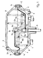
- the pneumatic actuator shown in Fig. 1 has a housing which is composed of a shell-like bottom part 1 and a shell-like cover part 2, the connection of the two housing parts 1 and 2 on the flanges 1a and 2a via screw connections 1b.
- a diaphragm plate 3 is arranged, to which a spindle 5 is fastened via a screw connection 5a, 5b.
- the spindle 5 is sealingly guided through the base part 1 and connected to an actuator in a manner not shown.
- a membrane 4 is arranged, which is connected to the side walls of the housing in such a way that the outer edge of the membrane 4 is clamped between the flanges 1a and 2a. In this way, the diaphragm plate 3 can be moved up and down in the direction of the spindle 5 in the housing.
- a gas supply nozzle 6 is arranged in the base part 1 and a gas supply nozzle 7 is arranged in the cover part 2.
- the diaphragm plate 3 moves upwards or downwards, in each case against the restoring forces which are generated by coil springs 8 which are arranged in the housing and on the one hand on the diaphragm plate 3 and on the other hand support either on the bottom part 1 or on the cover part 2.
- This is due to the appropriate design of the membrane plate ensured that this can be arranged in two different positions in the housing. These two layers are shown in FIG. 1 in the left and right half of the figure. In the left half of Fig.
- the diaphragm plate 3 is arranged so that the diaphragm 4, which is fastened to the diaphragm plate by means of a screw 5c screwed into a bore 5b of the diaphragm plate 3, is located on the top and the coil springs 8 are located on the bottom part 1 support.
- the spindle 5 is screwed into a bore 5a on the side of the diaphragm plate 3 carrying the support surfaces.
- the diaphragm plate 3 is inserted into the housing in such a way that the diaphragm 4 is located on its side facing the bottom part 1 and is fastened together with the end of the spindle 5 to the bore 5b in the diaphragm plate 3.
- the coil springs 8 are supported on the one hand on the diaphragm plate 3 and on the other hand on the cover part 2.
- the circular membrane plate has, on the side on which the coil springs 8 are to be supported, circumferentially penetrating, essentially circular grooves 9 and circular recesses 10.
- the recesses 10 have essentially circular graduations 10a on their edge.
- the base of the recesses 10 corresponding to the base of the grooves 9 is at a greater distance from the upper surface E of the membrane plate 3 serving as a reference surface than the surface of the graduations 10a.
- the coil spring is inserted more or less deeply in the diaphragm plate 3. From Fig. 1 it can be easily read that a coil spring 8, which rests on the bottom 9a of the grooves 9, causes a lower restoring force in the same position of the diaphragm plate 3 than if it rests on the surface 10a of the gradation of one of the recesses 10.
Landscapes
- Engineering & Computer Science (AREA)
- Physics & Mathematics (AREA)
- Fluid Mechanics (AREA)
- Mechanical Engineering (AREA)
- General Engineering & Computer Science (AREA)
- Actuator (AREA)
- Fluid-Driven Valves (AREA)
- Supply Devices, Intensifiers, Converters, And Telemotors (AREA)
- Fluid-Damping Devices (AREA)
Applications Claiming Priority (2)
| Application Number | Priority Date | Filing Date | Title |
|---|---|---|---|
| DE3224905 | 1982-07-03 | ||
| DE19823224905 DE3224905A1 (de) | 1982-07-03 | 1982-07-03 | Pneumatischer stellantrieb |
Publications (2)
| Publication Number | Publication Date |
|---|---|
| EP0098436A1 EP0098436A1 (de) | 1984-01-18 |
| EP0098436B1 true EP0098436B1 (de) | 1985-01-09 |
Family
ID=6167534
Family Applications (1)
| Application Number | Title | Priority Date | Filing Date |
|---|---|---|---|
| EP83105967A Expired EP0098436B1 (de) | 1982-07-03 | 1983-06-18 | Pneumatischer Stellantrieb |
Country Status (6)
| Country | Link |
|---|---|
| US (1) | US4505188A (enExample) |
| EP (1) | EP0098436B1 (enExample) |
| JP (1) | JPS5923108A (enExample) |
| CA (1) | CA1217099A (enExample) |
| DE (2) | DE3224905A1 (enExample) |
| ES (1) | ES523783A0 (enExample) |
Families Citing this family (12)
| Publication number | Priority date | Publication date | Assignee | Title |
|---|---|---|---|---|
| FR2557950B1 (fr) * | 1984-01-10 | 1986-09-26 | Joucomatic Sa | Perfectionnements apportes aux vannes a commande par piston |
| JPS631902U (enExample) * | 1986-06-20 | 1988-01-08 | ||
| US4774874A (en) * | 1987-03-26 | 1988-10-04 | Carmeli Adahan | Rolling diaphragm construction and piston-cylinder assembly including same particularly useful for suction or compression pumps |
| JPH0216805U (enExample) * | 1988-07-20 | 1990-02-02 | ||
| DE9110959U1 (de) * | 1991-06-06 | 1991-10-31 | Arca Regler GmbH, 4154 Tönisvorst | Pneumatischer Membranstellantrieb |
| DE4305631C2 (de) * | 1993-02-24 | 1997-03-20 | Hans Bender | Druckmittelgesteuerter Antrieb |
| USD358454S (en) | 1993-07-22 | 1995-05-16 | Arca Regler Gmbh | Control valve |
| US5507217A (en) * | 1994-09-30 | 1996-04-16 | Indian Head Industries, Inc. | Perforate diaphragm alignment system for spring brake actuators |
| US6957806B2 (en) * | 2002-12-12 | 2005-10-25 | The Modern Group Limited | Airspring assembly |
| JP5973197B2 (ja) * | 2012-03-23 | 2016-08-23 | 旭有機材株式会社 | ピストン式作動流体圧アクチュエータ、および制御弁 |
| JP6072396B2 (ja) * | 2014-11-25 | 2017-02-01 | 三菱電機株式会社 | 空圧式アクチュエータ |
| US10077850B2 (en) * | 2016-05-03 | 2018-09-18 | Borgwarner Inc. | Reverse taper piston for pneumatic actuators |
Family Cites Families (21)
| Publication number | Priority date | Publication date | Assignee | Title |
|---|---|---|---|---|
| US2172694A (en) * | 1939-09-12 | Aneroid altimetric device with a | ||
| CH84325A (de) * | 1919-03-03 | 1920-03-01 | Autoraeder Ges M B H | Lager für Schraubenfedern |
| FR839045A (fr) * | 1937-12-01 | 1939-03-22 | Soc Fr Regulateurs Arca | Perfectionnement au relais de commande à fluide |
| FR1041709A (fr) * | 1951-04-10 | 1953-10-26 | Perfectionnements aux dispositifs limiteurs de pression | |
| US2883998A (en) * | 1954-01-14 | 1959-04-28 | Frances J Broughton | Vacuum control valve |
| US2950739A (en) * | 1957-03-06 | 1960-08-30 | Chaplin Fulton Mfg Co | Diaphragm motor |
| US2966143A (en) * | 1957-07-18 | 1960-12-27 | Powers Regulator Corp | Pneumatic control system |
| US3241805A (en) * | 1962-10-23 | 1966-03-22 | Powers Regulator Co | Valve |
| US3166251A (en) * | 1963-10-28 | 1965-01-19 | Sr William J Stitt | Sprinkler and valve |
| GB1231579A (enExample) * | 1967-11-01 | 1971-05-12 | ||
| US3448659A (en) * | 1967-11-16 | 1969-06-10 | Gen Motors Corp | Piloted vacuum actuator |
| DE1966675A1 (de) * | 1969-03-04 | 1974-06-12 | Samson Apparatebau Ag | Ventil od. dgl. mit umkehrbarer druckmittel betaetigung |
| US3866521A (en) * | 1971-05-31 | 1975-02-18 | Ernesto Juan Weber | Control device |
| US3815471A (en) * | 1972-03-30 | 1974-06-11 | J Kobelt | Self-adjusting linear actuator |
| US3862751A (en) * | 1972-09-28 | 1975-01-28 | Bernard L Schwaller | Dual stage compressor spring |
| DE2257690A1 (de) * | 1972-11-24 | 1974-05-30 | Walter Beck Kg Kontroll Und Fe | Hydraulisch oder druckluftbetaetigte geschlossene membran-hub-dose |
| DE2353168A1 (de) * | 1973-10-24 | 1975-04-30 | Gulde Regelarmaturen Kg | Pneumatischer antrieb |
| US4046167A (en) * | 1976-02-06 | 1977-09-06 | Kawneer Company, Inc. | Mechanical accumulator |
| DE2821676A1 (de) * | 1978-05-18 | 1979-11-22 | Gec Sunvic Regler Gmbh | Pneumatisches geraet mit einer ringfoermigen druckbeaufschlagten membran |
| US4258611A (en) * | 1979-05-14 | 1981-03-31 | Schmelzer Corporation | Vacuum motor for carburetors |
| GB2091807B (en) * | 1981-01-26 | 1985-01-03 | British Gas Corp | Fluid operated actuator for a flow control valve |
-
1982
- 1982-07-03 DE DE19823224905 patent/DE3224905A1/de not_active Withdrawn
-
1983
- 1983-06-16 US US06/504,964 patent/US4505188A/en not_active Expired - Lifetime
- 1983-06-18 EP EP83105967A patent/EP0098436B1/de not_active Expired
- 1983-06-18 DE DE8383105967T patent/DE3360045D1/de not_active Expired
- 1983-06-23 CA CA000431063A patent/CA1217099A/en not_active Expired
- 1983-07-01 ES ES523783A patent/ES523783A0/es active Granted
- 1983-07-01 JP JP58118416A patent/JPS5923108A/ja active Granted
Also Published As
| Publication number | Publication date |
|---|---|
| JPS5923108A (ja) | 1984-02-06 |
| US4505188A (en) | 1985-03-19 |
| DE3224905A1 (de) | 1984-01-05 |
| DE3360045D1 (en) | 1985-02-21 |
| EP0098436A1 (de) | 1984-01-18 |
| JPH0313442B2 (enExample) | 1991-02-22 |
| ES8403579A1 (es) | 1984-04-01 |
| CA1217099A (en) | 1987-01-27 |
| ES523783A0 (es) | 1984-04-01 |
Similar Documents
| Publication | Publication Date | Title |
|---|---|---|
| EP0098436B1 (de) | Pneumatischer Stellantrieb | |
| DE69004814T2 (de) | Baustein. | |
| DE2319114B2 (de) | Durchflussrichtventil | |
| DE102014002182A1 (de) | Zweiachsig auslenkbares monolithisches Festkörpergelenk | |
| DE102019005799A1 (de) | Drehtisch | |
| EP3164608A1 (de) | Ventil-baukastensystem | |
| DE2346343C3 (de) | Anordnung zur geradlinigen Führung eines Maschinenelements | |
| AT393008B (de) | Fluidventil | |
| DE2010389A1 (de) | Vorrichtung zur gegenseitigen Führung von zwei Maschinenteilen, die sich gegeneinander mittels einer Arbeitsbewegung verschieben oder drehen | |
| EP0121849A2 (de) | Ventileinrichtung mit einstellbarer Funktion | |
| DE19943605C2 (de) | Adaptive Werkstückspannvorrichtung | |
| EP0463394A1 (de) | Elektromagnetisch betätigbares Wegeventil | |
| DE202022107282U1 (de) | Spann- und Positioniermodul | |
| DE3302625A1 (de) | Offene waelzmutter | |
| DE3888677T2 (de) | Orbitaler pisch für werkzeugmaschinen. | |
| DE4007096C2 (enExample) | ||
| EP0108951A1 (de) | Wegeventil | |
| DE69601753T2 (de) | Matrizenbaugruppe für verschiedene Werkstückarten | |
| DE917433C (de) | Nockenschalter | |
| DE4324465A1 (de) | Mehrwegeventil, insbesondere zur Steuerung pneumatischer Motoren | |
| DE2304992C2 (de) | Druckmittelbetätigte Einrichtung zum Lockern eines geformten Gießereikernes | |
| DE102006049047A1 (de) | Werkzeugmaschine und Bearbeitungswerkzeug für eine Werkzeugmaschine | |
| DE1550189B1 (de) | Hydraulisches Steuerventil fuer Nachformfraesmas nen | |
| DE102018115116A1 (de) | Polverlängerung für ein Magnetspannsystem, Magnetspannfeld für ein Magnetspannsystem und Magnetspannsystem | |
| DE3041724A1 (de) | Zeichengeraet |
Legal Events
| Date | Code | Title | Description |
|---|---|---|---|
| PUAI | Public reference made under article 153(3) epc to a published international application that has entered the european phase |
Free format text: ORIGINAL CODE: 0009012 |
|
| 17P | Request for examination filed |
Effective date: 19831017 |
|
| AK | Designated contracting states |
Designated state(s): DE FR GB IT |
|
| ITF | It: translation for a ep patent filed | ||
| GRAA | (expected) grant |
Free format text: ORIGINAL CODE: 0009210 |
|
| AK | Designated contracting states |
Designated state(s): DE FR GB IT |
|
| REF | Corresponds to: |
Ref document number: 3360045 Country of ref document: DE Date of ref document: 19850221 |
|
| ET | Fr: translation filed | ||
| PLBE | No opposition filed within time limit |
Free format text: ORIGINAL CODE: 0009261 |
|
| STAA | Information on the status of an ep patent application or granted ep patent |
Free format text: STATUS: NO OPPOSITION FILED WITHIN TIME LIMIT |
|
| 26N | No opposition filed | ||
| ITTA | It: last paid annual fee | ||
| PGFP | Annual fee paid to national office [announced via postgrant information from national office to epo] |
Ref country code: GB Payment date: 20010502 Year of fee payment: 19 |
|
| PGFP | Annual fee paid to national office [announced via postgrant information from national office to epo] |
Ref country code: FR Payment date: 20010531 Year of fee payment: 19 |
|
| PGFP | Annual fee paid to national office [announced via postgrant information from national office to epo] |
Ref country code: DE Payment date: 20010627 Year of fee payment: 19 |
|
| REG | Reference to a national code |
Ref country code: GB Ref legal event code: IF02 |
|
| PG25 | Lapsed in a contracting state [announced via postgrant information from national office to epo] |
Ref country code: GB Free format text: LAPSE BECAUSE OF NON-PAYMENT OF DUE FEES Effective date: 20020618 |
|
| PG25 | Lapsed in a contracting state [announced via postgrant information from national office to epo] |
Ref country code: DE Free format text: LAPSE BECAUSE OF NON-PAYMENT OF DUE FEES Effective date: 20030101 |
|
| GBPC | Gb: european patent ceased through non-payment of renewal fee |
Effective date: 20020618 |
|
| PG25 | Lapsed in a contracting state [announced via postgrant information from national office to epo] |
Ref country code: FR Free format text: LAPSE BECAUSE OF NON-PAYMENT OF DUE FEES Effective date: 20030228 |
|
| REG | Reference to a national code |
Ref country code: FR Ref legal event code: ST |