EP0098257A2 - Fittings forming an articulation for wings such as shutters, doors or the like - Google Patents
Fittings forming an articulation for wings such as shutters, doors or the like Download PDFInfo
- Publication number
- EP0098257A2 EP0098257A2 EP83870066A EP83870066A EP0098257A2 EP 0098257 A2 EP0098257 A2 EP 0098257A2 EP 83870066 A EP83870066 A EP 83870066A EP 83870066 A EP83870066 A EP 83870066A EP 0098257 A2 EP0098257 A2 EP 0098257A2
- Authority
- EP
- European Patent Office
- Prior art keywords
- holes
- hinge
- fitting
- fixing
- elements
- Prior art date
- Legal status (The legal status is an assumption and is not a legal conclusion. Google has not performed a legal analysis and makes no representation as to the accuracy of the status listed.)
- Granted
Links
Images


Classifications
-
- E—FIXED CONSTRUCTIONS
- E05—LOCKS; KEYS; WINDOW OR DOOR FITTINGS; SAFES
- E05D—HINGES OR SUSPENSION DEVICES FOR DOORS, WINDOWS OR WINGS
- E05D5/00—Construction of single parts, e.g. the parts for attachment
- E05D5/10—Pins, sockets or sleeves; Removable pins
-
- E—FIXED CONSTRUCTIONS
- E05—LOCKS; KEYS; WINDOW OR DOOR FITTINGS; SAFES
- E05D—HINGES OR SUSPENSION DEVICES FOR DOORS, WINDOWS OR WINGS
- E05D7/00—Hinges or pivots of special construction
- E05D7/04—Hinges adjustable relative to the wing or the frame
- E05D7/0415—Hinges adjustable relative to the wing or the frame with adjusting drive means
-
- E—FIXED CONSTRUCTIONS
- E05—LOCKS; KEYS; WINDOW OR DOOR FITTINGS; SAFES
- E05D—HINGES OR SUSPENSION DEVICES FOR DOORS, WINDOWS OR WINGS
- E05D5/00—Construction of single parts, e.g. the parts for attachment
- E05D5/10—Pins, sockets or sleeves; Removable pins
- E05D2005/102—Pins
- E05D2005/106—Pins with non-cylindrical portions
-
- E—FIXED CONSTRUCTIONS
- E05—LOCKS; KEYS; WINDOW OR DOOR FITTINGS; SAFES
- E05Y—INDEXING SCHEME RELATING TO HINGES OR OTHER SUSPENSION DEVICES FOR DOORS, WINDOWS OR WINGS AND DEVICES FOR MOVING WINGS INTO OPEN OR CLOSED POSITION, CHECKS FOR WINGS AND WING FITTINGS NOT OTHERWISE PROVIDED FOR, CONCERNED WITH THE FUNCTIONING OF THE WING
- E05Y2900/00—Application of doors, windows, wings or fittings thereof
- E05Y2900/10—Application of doors, windows, wings or fittings thereof for buildings or parts thereof
- E05Y2900/13—Application of doors, windows, wings or fittings thereof for buildings or parts thereof characterised by the type of wing
- E05Y2900/146—Shutters
-
- E—FIXED CONSTRUCTIONS
- E05—LOCKS; KEYS; WINDOW OR DOOR FITTINGS; SAFES
- E05Y—INDEXING SCHEME RELATING TO HINGES OR OTHER SUSPENSION DEVICES FOR DOORS, WINDOWS OR WINGS AND DEVICES FOR MOVING WINGS INTO OPEN OR CLOSED POSITION, CHECKS FOR WINGS AND WING FITTINGS NOT OTHERWISE PROVIDED FOR, CONCERNED WITH THE FUNCTIONING OF THE WING
- E05Y2900/00—Application of doors, windows, wings or fittings thereof
- E05Y2900/20—Application of doors, windows, wings or fittings thereof for furnitures, e.g. cabinets
Definitions
- the present invention relates to a hinge fitting for a door leaf, residential shutter or piece of furniture or the like, of the type comprising first and second elements mounted respectively on a fixed support forming a frame and said leaf, one of the elements comprising a pivot, while the other element comprises a crapaudine around the pivot, the pivot and the crapaudine being fixed to the frame or to the leaf by means of a hinge comprising fixing holes intended to receive fixing elements, and an adjustment member intended to adjust the positioning and / or the inclination of said fitting and of the door or flap during its installation, at least two of the fixing holes having an oblong shape, extending substantially in the extension of the 'common longitudinal axis of said holes or optionally along parallel axes.
- US Pat. No. 2,611,921 discloses a hinge pivoting on plug hinges and one of the hinges of which consists of a rectangular metal blade has a rectangular hole. Said blade can slide along a groove formed in a fixing plate fixed to a fixed support or to a leaf using screws.
- An adjustment member consisting of an octagonal piece comprising an eccentric fixing hole is engaged in the above-mentioned rectangular hole, in a determined position, so as to adjust the position of the hinge relative to the fixing plate.
- the octagonal piece is fixed to the support or to the aforementioned leaf, also using a screw.
- the assembly constituted by the fixing plate, the metal blade forming the hinge and the octagonal part, is covered with a covering plate intended to hold the octagonal part in place and to hide it by a united surface, forming a third thickness.
- the problem relating to the fitting of a fitting results from the difficulty encountered by the installers in drilling fixing holes in the masonry in the correct position, despite the use of a template.
- the object of the present invention is to eliminate the drawbacks described above. It offers a fitting forming a hinge for the door leaf, flap, housing or cabinet or the like, of the type comprising first and second elements mounted respectively on a frame forming a fixed carrier and said door, one of the members having a pivot, while the other element comprises a rotary member around the pivot, the pivot and the clamp being fixed to the frame or to the leaf by means of a hinge comprising fixing holes intended to receive fixing elements, and an adjusting member intended to adjust the positioning and / or the inclination of said fitting and: of the door or shutter during its installation, at least two of the fixing holes, having an oblong shape, extending substantially in the extension of the common longitudinal axis of said holes or optionally along parallel axes, essentially characterized in that the pivotally mounted adjustment member controls when it is rotated, the displacement nt oblong holes relative to the fastening elements.
- the aforementioned adjustment member is fixed to the aforementioned frame or leaf and comprises a movable cylindrical part forming a cam acting on the edges of an oblong light formed optionally in each aforementioned hinge.
- a hinge has three fixing holes of oblong shape, the intermediate hole having a longitudinal axis perpendicular to the common longitudinal axis of each of the two end holes.
- the adjusting member advantageously comprises a fixing element serving at the same time as a fixing member.
- the invention also relates to a method for fixing a fitting as described above.
- This process is essentially characterized in that one introduces into any of the above oblong-shaped holes, an adjustment member consisting of a fastening element and a said cam, which is actuated in rotation at using a key in order to adjust the positioning and / or the inclination of each of the elements of said fitting.
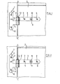
- Figure 1 shows a type of fitting, designated as a whole by the reference notation 1 and intended to ensure the pivoting around a vertical axis of a leaf 2 which can be a door or a shutter of which only the upper part has been represented.
- fittings comprise a first element mounted on the leaf 2 and forming a horizontal hinge 3, and a second element 4 forming a hinge fixed on a fixed support forming the frame of the leaf 2.
- first and second elements are fixed respectively to the leaf 2 and to the frame by means of fixing elements not shown, such as screws, lag screws, burglar-resistant bolts or the like, introduced into corresponding holes made in each. of these elements which thus articulate with each other in order to ensure the pivoting of the leaf 2 around a vertical axis L L '.
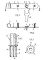
- Each horizontal hinge 3 as illustrated in FIGS. 3 and 4, is constituted by a metal tab of substantially rectangular shape and crossed by holes 5, 6 for the passage of fastening elements 7 such as screws.
- the holes 5, 6 advantageously have an oblong shape and extend in the extension of one another.
- these oblong holes 5, 6 are in longitudinal alignment on the hinge 3 and are located on the axis of symmetry of this tab.
- One of the ends of the hinge 3 ends in a rounded loop substantially closing in on itself so as to define a substantially cylindrical open passage and whose axis is perpendicular to the axis of symmetry of the fixing lug.
- This rotary member 8 also called the node of the horizontal hinge, acts as a basket as shown in FIG. 4.
- the element 4 forming a hinge is illustrated in FIG. 5. It has substantially the shape of a T, the head of which is arranged vertically.
- the head of the T of this element 4 acts as a fixing lug for this element on the frame and has fixing holes 9, -10-of oblong shape intended to accommodate fixing elements not shown which can be screws, funds, burglar-resistant bolts or the like.
- these holes 9 and 10 are aligned longitudinally and are located in the axis of symmetry of the elongated fixing lug and of substantially rectangular shape.
- the horizontal leg 11 of the T-shaped part of the element 4 forming a hinge has at its end a pivot axis or pin 12 disposed perpendicularly to the leg of the T and integral therewith.
- the pivot 12 can also be removably mounted to the element 4 forming a hinge, so as to be able to transform each hinge into a hinge and vice versa.
- Such a pivot is shown in FIGS. 6 and 7 and includes an elongated hollow cylindrical upper part 13 for pivoting around the latter of the corresponding hinge, a cylindrical lower part. elongated 14 which can be inserted into an opening corresponding to the end of the hinge, and an annular part 15 for supporting the pivot 12 on the upper edge of the basket.
- the lower part 14 has ribs 16 extending along this part 14 and regularly spaced around it.
- these ribs 16 are four in number and allow correct positioning of the pivot 12 in its corresponding opening 8.
- each fixing lug of each element 3, 4 of the fitting comprises an adjustment light 17 preferably situated between two holes 5, 6 and 9, 10 intended to each receive a fixing element 7, as shown in FIG. 5.
- the longitudinal axis of this possible oblong lumen 17 is perpendicular to the axis of symmetry of the fixing lug and the geometric center of this lumen is in longitudinal alignment with the geometric centers of the oblong holes 5,6 and 9,10 .
- this oblong light 17 are also found on the horizontal hinge of Figure 3 and is shown in solid lines.
- each fixing lug of each fitting element is associated a control member 18 which, in the present case, and for the sake of simplification, is shown only in association with the horizontal hinge of FIG. 3.
- control member 18 comprises a head portion 19 under which is integrally attached a cylindrical portion 20 forming a cam.
- the longitudinal axis of the cylindrical part 20 is eccentric relative to the central axis of the head 19 of the control member 18.
- a bore 21 coaxial with the axis of the head 19 crosses on either side the control member so as to allow the passage of a fastening element 7 of the control member 18 on the leaf or the dormant.
- a counterbore 22 is produced in the upper part of the head 19 coaxially with the bore 21 to allow passage of the head of the fixing element 7.
- the external diameter of the cylindrical part 20 of the control member can be identical to the diameter of the passages defined at each of the opposite ends of each oblong hole. It is thus understood that the control member 18 can be mounted on each fitting element by inserting the cylindrical part 20 in each adjustment lumen 17, the head 19 of the member 18 coming to bear on the fixing lug of each element fittings by means of a circular bearing surface 23 serving as a connection surface between the head and the cylindrical part 20 forming a cam.
- the fixing element 7 of the control member 18 serves as a fulcrum or pivot point for the movement of the cam 20.
- the lower end of the cylindrical part 20 is flush with the bearing surface of the hinge 3 on the leaf 2 when the control member 18 is mounted on the support leg.
- each fitting element is carried out as follows.
- Each fitting element is mounted on its appropriate support (casement or frame) using the fixing screws 7 passing respectively through the oblong holes 5, 6 and 9, 10 and in holes drilled respectively in the leaf and the frame using a template not shown.
- the screws 7 are not fully tightened.
- each control member 18 is introduced into the oblong adjustment light 17.
- This adjustment member 18 is held by the screw 7 which is not fully tightened and serving as a pivot for the displacement of the cylindrical part 20 forming a cam.
- the head 19 of the control member 18 having a hexagonal shape, it is therefore possible, using a key 24, to rotate this member 18 which, by means of the cylindrical part 20 forming cam acting on the longitudinal edges of the adjustment light, pushes the fitting element longitudinally on the screws 7 which thus serve initially guide to this fitting element.
- the adjusting member 18 makes it possible to adjust the positioning of the leaf relative to the frame, both in a horizontal and vertical direction in order to compensate for any misalignment caused by a compaction of the building or due to an imprecision in drilling the holes. fixing when installing the shutter or door.
- the adjustment system according to the invention also allows subsequent adjustment of the position of the leaf if the need arises, for example as a result of the work of the masonry or the wood of the leaf over time.
- this possibility of subsequent adjustment will be made by slightly loosening the fixing screws inserted in the holes 5, 6 and 9, 10, by loosening the screw 7 of the control member 18 and by rotating using a key 24 suitable for the head 19 of this control member 18 for the thrust movement of the fitting element.
- the holes 5, 6 instead of being made along the longitudinal axis of the fitting element 3 can be made along a vertical axis of this element, while the adjustment light 17 will be produced along the longitudinal axis of the fitting. It is therefore possible to combine this type of fitting element with another fitting element having holes made along the longitudinal axis of the fitting and an adjustment light perpendicular to this axis, the combination of these two fitting elements allowing also their displacement relative to each other in a horizontal direction and a vertical direction.
- the adjustment lumen into which the cam portion 20 of the control member 18 is inserted may also have a substantially oval shape, the diameter of the cam corresponding to the smallest diameter of this oval bore.
- the adjustment system according to the invention can also be applied to the types of fittings respectively comprising a square hinge (FIG. 10), a hinge for the connection of two leaves of a double flap (FIG. 11), a vertical folded hinge (figure 12) and a horizontal hinge (figure 13).
Abstract
Description
La présente invention concerne une ferrure formant charnière pour battant de porte,de volet d'habitation ou de meuble ou analogue, du type comprenant des premier et second éléments montés respectivement sur un support fixe formant dormant et ledit battant, l'un des éléments comportant un pivot, tandis que l'autre élément comporte une crapaudine autour du pivot, le pivot et la crapaudine étant fixés au dormant ou au battant par l'intermédiaire d'une penture comprenant des trous de fixation destinés à recevoir des éléments de fixation, et un organe de réglage destiné à ajuster le positionnement et/ou l'inclinaison de ladite ferrure et de la porte ou volet lors de sa pose, deux au moins des trous de fixation présentant une forme oblongue, s'étendant sensiblement dans le prolongement de l'axe longitudinal commun desdits trous ou éventuellement le long d'axes parallèles.The present invention relates to a hinge fitting for a door leaf, residential shutter or piece of furniture or the like, of the type comprising first and second elements mounted respectively on a fixed support forming a frame and said leaf, one of the elements comprising a pivot, while the other element comprises a crapaudine around the pivot, the pivot and the crapaudine being fixed to the frame or to the leaf by means of a hinge comprising fixing holes intended to receive fixing elements, and an adjustment member intended to adjust the positioning and / or the inclination of said fitting and of the door or flap during its installation, at least two of the fixing holes having an oblong shape, extending substantially in the extension of the 'common longitudinal axis of said holes or optionally along parallel axes.
par le brevet américain No 2 611 921, on connaît une paumelle pivotant sur des gonds à fiches et dont une des pentures constituée d'une lame métallique rectangulaire comporte un trou rectangulaire. Ladite lame peut coulisser le long d'une rainure ménagée dans une plaquette de fixation fixée sur un support fixe ou sur un battant à l'aide de vis.US Pat. No. 2,611,921 discloses a hinge pivoting on plug hinges and one of the hinges of which consists of a rectangular metal blade has a rectangular hole. Said blade can slide along a groove formed in a fixing plate fixed to a fixed support or to a leaf using screws.
Un organe de réglage constitué d'une pièce octogonale comportant un trou de fixation excentré est engagé dans le trou rectangulaire susdit, dans une position déterminée, de manière à ajuster la position de la penture par rapport à la plaquette de fixation.An adjustment member consisting of an octagonal piece comprising an eccentric fixing hole is engaged in the above-mentioned rectangular hole, in a determined position, so as to adjust the position of the hinge relative to the fixing plate.
Une fois mis en place, la pièce octogonale est fixée sur le support ou sur le battant susdit, également à l'aide d'une vis. L'ensemble constitué par la plaquette de fixation, la lame métallique formant penture et la pièce octogonale,est recouvert d'une plaquette de recouvrement destinée à maintenir en place la pièce octogonale et à cacher celle-ci par une surface unie, formant une troisième épaisseur.Once in place, the octagonal piece is fixed to the support or to the aforementioned leaf, also using a screw. The assembly constituted by the fixing plate, the metal blade forming the hinge and the octagonal part, is covered with a covering plate intended to hold the octagonal part in place and to hide it by a united surface, forming a third thickness.
L'inconvénient majeur de cette ferrure connue, réside en la difficulté qu'éprouvent les installateurs à ajuster le positionnement de ladite ferrure lors de la pose d'un volet ou d'une porte. En outre, il est impossible de corriger le jeu ultérieur d'un battant, sans démonter complètement ladite ferrure. Enfin cette ferrure connue comporte de nombreuses pièces de formes complexes qui alourdissent son coût de fabrication.The major drawback of this known fitting lies in the difficulty that installers experience in adjusting the positioning of said fitting when installing a shutter or a door. In addition, it is impossible to correct the subsequent play of a leaf, without completely dismantling said fitting. Finally, this known fitting comprises numerous parts of complex shapes which increase its manufacturing cost.
Le problème relatif à la pose d'une ferrure résulte de la difficulté rencontrée par les installateurs à percer des trous de fixation dans la maçonnerie en position correcte et ceci malgré l'emploi d'un gabarit.The problem relating to the fitting of a fitting results from the difficulty encountered by the installers in drilling fixing holes in the masonry in the correct position, despite the use of a template.
En effet, il est très difficile d'obtenir des trous dans les murs à des endroits précis, éventuellement parfaitement alignés, en raison du fait que la force de l'outil de forage utilisé, suit le chemin de moindre résistance dans les matériaux composites de la maçonnerie. Ce défaut de précision lors du forage, a pour inconvénient une pose incorrecte des battants. Le défaut peut être tel que la fermeture du ou des battants soit éventuellement empêchée.Indeed, it is very difficult to obtain holes in the walls at precise locations, possibly perfectly aligned, due to the fact that the force of the drilling tool used follows the path of least resistance in composite materials of masonry. This lack of precision during drilling has the disadvantage of incorrectly fitting the leaves. The fault may be such that the closing of the leaf (s) is possibly prevented.
La présente invention a pour but d'éliminer les inconvénients décrits ci-dessus. Elle propose une ferrure formant charnière pour battant de porte,de volet, d'habitation ou de meuble ou analogue, du type comprenant des premier et second éléments montés respectivement sur un support fixe formant dormant et ledit battant, l'un des éléments comportant un pivot, tandis que l'autre élément comporte un organe rotatif autour du pivot, le pivot et la crapaudine étant fixés au dormant ou au battant par l'intermédiaire d'une penture comprenant des trous de fixation destinés à recevoir des éléments de fixation, et un organe de réglage destiné à ajuster le positionnement et/ou l'inclinaison de ladite ferrure et: de la porte ou volet lors de sa pose, deux au moins des trous de fixation, présentant une forme oblongue, s'étendant sensiblement dans le prolongement de l'axe longitudinal commun desdits trous ou éventuellement le long d'axes parallèles, essentiellement caractérisé en ce que l'organe de réglage monté pivotant contrôle lors de son actionnement en rotation, le déplacement des trous de forme oblongue par rapport aux éléments de fixation.The object of the present invention is to eliminate the drawbacks described above. It offers a fitting forming a hinge for the door leaf, flap, housing or cabinet or the like, of the type comprising first and second elements mounted respectively on a frame forming a fixed carrier and said door, one of the members having a pivot, while the other element comprises a rotary member around the pivot, the pivot and the clamp being fixed to the frame or to the leaf by means of a hinge comprising fixing holes intended to receive fixing elements, and an adjusting member intended to adjust the positioning and / or the inclination of said fitting and: of the door or shutter during its installation, at least two of the fixing holes, having an oblong shape, extending substantially in the extension of the common longitudinal axis of said holes or optionally along parallel axes, essentially characterized in that the pivotally mounted adjustment member controls when it is rotated, the displacement nt oblong holes relative to the fastening elements.
Suivant une particularité de l'invention, l'organe de réglage précité est fixé au dormant ou au battant précité et comprend une partie mobile cylindrique formant came agissant sur les bords d'une lumière de forme oblongue ménagée éventuellement dans chaque penture précitée.According to a feature of the invention, the aforementioned adjustment member is fixed to the aforementioned frame or leaf and comprises a movable cylindrical part forming a cam acting on the edges of an oblong light formed optionally in each aforementioned hinge.
Dans une forme de réalisation particulière, une penture comporte trois trous de fixation de forme oblongue, le trou intermédiaire présentant un axe longitudinal perpendiculaire à l'axe longitudinal commun de chacun des deux trous extrêmes.In a particular embodiment, a hinge has three fixing holes of oblong shape, the intermediate hole having a longitudinal axis perpendicular to the common longitudinal axis of each of the two end holes.
L'organe de réglage comporte avantageusement un élément de fixation servant en même temps d'organe de fixation.The adjusting member advantageously comprises a fixing element serving at the same time as a fixing member.
L'invention concerne également un procédé pour fixer une ferrure telle que décrite ci-dessus. Ce procédé est essentiellement caractérisé en ce qu'on introduit dans l'un quelconque des trous de forme oblongue susdits, un organe de réglage constitué d'un élément de fixation et d'une came susdite, que l'on actionne en rotation à l'aide d'une clef en vue d'ajuster le positionnement et/ou l'inclinaison de chacun des éléments de ladite ferrure.The invention also relates to a method for fixing a fitting as described above. This process is essentially characterized in that one introduces into any of the above oblong-shaped holes, an adjustment member consisting of a fastening element and a said cam, which is actuated in rotation at using a key in order to adjust the positioning and / or the inclination of each of the elements of said fitting.
D'autres particularités et détails de l'invention apparaitront au cours de la description détaillée suivante, faite en référence aux dessins schématiques annexés au présent mémoire descriptif illustrant plusieurs modes de réalisation de l'invention, donnés uniquement à titre d'exemples.Other particularities and details of the invention will appear during the following detailed description, given with reference to the schematic drawings annexed to this descriptive memory illustrating several embodiments of the invention, given solely by way of examples.
Dans ces figures :
- - la figure 1 est une vue partielle d'un volet comportant un type de ferrure selon l'invention et disposé de manière incorrecte;
- - la figure 2 est une vue analogue à celle de la figure 1. Elle montre comment le positionnement incorrect peut être ajusté au moyen de la ferrure suivant l'invention;
- - la figure 3 montre une vue de dessous d'une penture horizontale avec organe de commande;
- - la figure 4 est une coupe longitudinale suivant la ligne IV-IV de la penture horizontale montrée à la figure 3;
- - la figure 5 montre un gond vertical en forme de T;
- - les figures 6 et 7 montrent un tourillon pouvant être monté de façon amovible;
- - la figure 8 est une vue en coupe axiale de l'organe de commande pour le réglage du positionnement de chaque élément de ferrure;
- - la figure 9 est une vue en plan de l'organe de commande montré à la figure 8;
- - les figures 10 à 13 montrent d'autres types de ferrures selon l'invention.
- - Figure 1 is a partial view of a flap comprising a type of fitting according to the invention and arranged incorrectly;
- - Figure 2 is a view similar to that of Figure 1. It shows how the incorrect positioning can be adjusted by means of the fitting according to the invention;
- - Figure 3 shows a bottom view of a horizontal hinge with control member;
- - Figure 4 is a longitudinal section along line IV-IV of the horizontal hinge shown in Figure 3;
- - Figure 5 shows a vertical T-shaped hinge;
- - Figures 6 and 7 show a pin which can be removably mounted;
- - Figure 8 is an axial sectional view of the control member for adjusting the positioning of each fitting element;
- - Figure 9 is a plan view of the control member shown in Figure 8;
- - Figures 10 to 13 show other types of fittings according to the invention.
Dans ces différentes figures, les mêmes notations de référence désignent des éléments identiques ou analogues.In these different figures, the same reference notations designate identical or analogous elements.
La figure 1 montre un type de ferrure, désigné dans son ensemble par la notation de référence 1 et destiné à assurer le pivotement autour d'un axe vertical d'un battant 2 pouvant être une porte ou un volet dont seule la partie supérieure a été représentée.Figure 1 shows a type of fitting, designated as a whole by the reference notation 1 and intended to ensure the pivoting around a vertical axis of a
Ces ferrures comprennent un premier élément monté sur le battant 2 et formant penture horizontale 3, et un second élément 4 formant gond fixé sur un support fixe formant dormant du battant 2.These fittings comprise a first element mounted on the
Ces-premier et second éléments sont fixés respectivement au battant 2 et au dormant par l'intermédiaire d'éléments de fixation non représentés,tels que vis, tire-fonds, boulons anti-effraction ou analogues, introduits dans des trous correspondants pratiqués dans chacun de ces éléments qui s'articulent ainsi entre eux afin d'assurer le pivotement du battant 2 autour d'un axe vertical L L'.These first and second elements are fixed respectively to the
Chaque penture horizontale 3, comme illustré aux figures 3 et 4, est constituée par une patte métallique de forme sensiblement rectangulaire et traversée par des trous 5, 6 pour le passage d'éléments de fixation 7 tels que des vis.Each
Les trous 5, 6 présentent avantageusement une forme oblongue et s'étendent dans le prolongement l'un de l'autre. Dans l'exemple considéré, ces trous oblongs 5, 6 sont en alignement longitudinal sur la penture 3 et sont situés sur l'axe de symétrie de cette patte.The
L'une des extrémités de la penture 3 se termine en une boucle arrondie se refermant sensiblement sur elle-même de manière à définir un passage ouvert sensiblement cylindrique et dont l'axe est perpendiculaire à l'axe de symétrie de la patte de fixation. Cet organe rotatif 8 appelé également noeud de la penture horizontale fait office de crapaudine comme représenté à la figure 4.One of the ends of the
L'élément 4 formant gond est illustré à la figure 5. Il présente sensiblement la forme d'un T dont la tête est disposée verticalement. La tête du T de cet élément 4 fait office de patte de fixation de cet élément sur le dormant et comporte des trous de fixation 9,-10-de forme oblongue destinés à accueillir des éléments de fixation non représentés pouvant être des vis, tire-fonds, boulons anti-effraction ou analogues. Comme dans le cas de la penture horizontale, ces trous 9 et 10 sont alignés longitudinalement et sont situés dans l'axe de symétrie de la patte de fixation allongée et de forme sensiblement rectangulaire.The
La jambe horizontale 11 de la partie en forme de T de l'élément 4 formant gond comporte à son extrémité un axe de pivotement ou tourillon 12 disposé de façon perpendiculaire par rapport à la jambe du T et solidaire de celle-ci.The
On comprend de ce qui précède, que l'arti-culation entre la penture horizontale 3 et l'élément 4 est réalisée par la rotation de la penture horizontale autour du tourillon 12 passant ainsi à travers le passage ouvert de la crapaudine 8 et s'étendant dans l'axe de l'articulation.It is understood from the above, that the articulation between the
Le pivot 12 peut être également monté de façon amovible à l'élément 4 formant gond, de manière à pouvoir transformer chaque gond en penture et vice-versa.The
Un tel pivot est représenté aux figures 6 et 7 et comprend une partie supérieure cylindrique creuse allongée 13 pour le pivotement autour de celle-ci de la penture correspondante, une partie inférieure cylindrique allongée 14 pouvant être insérée dans une ouverture correspondante à l'extrémité du gond, et une partie annulaire 15 d'appui du pivot 12 sur le bord supérieur de la crapaudine.Such a pivot is shown in FIGS. 6 and 7 and includes an elongated hollow cylindrical
La partie inférieure 14 comporte des nervures 16 s'étendant le long de cette partie 14 et régulièrement espacées autour de celle-ci. A titre d'exemple, ces nervures 16 sont au nombre de quatre et permettent un positionnement correct du pivot 12 dans son ouverture 8 correspondante.The
Avantageusement, chaque patte de fixation de chaque élément 3, 4 de la ferrure comporte une lumière de réglage 17 située, de préférence, entre deux trous 5, 6 et 9, 10 destinés à recevoir chacun un élément de fixation 7, comme représenté en figure 5. L'axe longitudinal de cette lumière 17 éventuelle oblongue est perpendiculaire à l'axe de symétrie de la patte de fixation et le centre géométrique de cette lumière est en alignement longitudinal avec les centres géométriques des perçages oblongs 5,6 et 9,10.Advantageously, each fixing lug of each
Bien entendu, la forme et la disposition de cette lumière oblongue 17 se retrouvent également sur la penture horizontale de la figure 3 et est représentée en trait plein.Of course, the shape and arrangement of this oblong light 17 are also found on the horizontal hinge of Figure 3 and is shown in solid lines.
Par ailleurs, à chaque patte de fixation de chaque élément de ferrure est associé un organe de commande 18 qui, dans le cas présent, et dans un but de simplification, est montré uniquement en association avec la penture horizontale de la figure 3.Furthermore, with each fixing lug of each fitting element is associated a
Comme représenté aux figures 8 et 9, l'organe de commande 18 comprend une partie formant tête 19 sous laquelle est solidairement rapportée une partie cylindrique 20 formant came. Comme il apparait clairement sur ces figures, l'axe longitudinal de la partie cylindrique 20 est excentré par rapport à l'axe central de la tête 19 de l'organe de commande 18.As shown in Figures 8 and 9, the
De plus, un alésage 21 coaxial à l'axe de la tête 19 traverse de part et d'autre l'organe de commande de façon à permettre le passage d'un élément de fixation 7 de l'organe de commande 18 sur le battant ou le dormant. Un lamage 22 est réalisé dans la partie supérieure de la tête 19 coaxialement à l'alésage 21 pour permettre le passage de la tête de l'élément de fixation 7.In addition, a
Le diamètre externe de la partie cylindrique 20 de l'organe de commande peut être identique au diamètre des passages définis à chacune des extrémités opposées de chaque perçage oblong. On comprend ainsi que l'organe de commande 18 peut être monté sur chaque élément de ferrures en insérant la partie cylindrique 20 dans chaque lumière de réglage 17, la tête 19 de l'organe 18 venant en appui sur la patte de fixation de chaque élément des ferrures par l'intermédiaire d'une surface d'appui circulaire 23 servant de surface de liaison entre la tête et la partie cylindrique 20 formant came.The external diameter of the
L'élément de fixation 7 de l'organe de commande 18 sert de point d'appui ou de pivot au déplacement de la came 20.The fixing
Comme représenté en figure 4, l'extrémité inférieure de la partie cylindrique 20 vient en affleurement avec la surface d'appui de la penture 3 sur le battant 2 lorsque l'organe de commande 18 est monté sur la patte d'appui.As shown in FIG. 4, the lower end of the
On comprend donc de ce qui précède que les trous 5, 6 et 9,10 susdits et la lumière 17 de forme oblongue définis dans chaque élément des ferrures permettent un réglage de la position de chacun de ces éléments par un déplacement relatif entre ces perçages oblongs et leurs vis de fixation 7 associées , ce déplacement relatif étant obtenu en agissant sur l'organe de commande 18.It is therefore understood from the above that the
Le positionnement de chaque élément de ferrure s'effectue comme suit .The positioning of each fitting element is carried out as follows.
Chaque élément de ferrure est monté sur son support approprié (battant ou dormant) à l'aide des vis de fixation 7 passant respectivement à travers les perçages oblongs 5, 6 et 9, 10 et dans des trous forés respectivement dans le battant et le dormant à l'aide d'un gabarit non montré. Les vis 7 ne sont pas serrées complètement.Each fitting element is mounted on its appropriate support (casement or frame) using the fixing screws 7 passing respectively through the
Ensuite, on introduit chaque organe de commande 18 dans la lumière de réglage de forme oblongue 17. Cet organe de réglage 18 est maintenu par la vis 7 non totalement serrée et servant de pivot au déplacement de la partie cylindrique 20 formant came.Then, each
La tête 19 de l'organe de commande 18 présentant une forme hexagonale, il est donc possible, à l'aide d'une clé 24, d'entrainer en rotation cet organe 18 qui, par l'intermédiaire de la partie cylindrique 20 formant came agissant sur les bords longitudinaux de la lumière de réglage, pousse longitudinalement l'élément de ferrure sur les vis 7 qui servent ainsi dans un premier temps de guide à cet élément de ferrure.The
Lorsque la position du battant par rapport à la ferrure est correcte, comme illustré à la figure 2, il suffit alors pour bloquer définitivement le réglage,de serrer définitivement chaque vis 7 pour maintenir fermement l'organe 18 et ensuite de bloquer définitivement les vis dans les trous oblongs 5, 6 et 9, 10.When the position of the leaf relative to the fitting is correct, as illustrated in FIG. 2, it then suffices to definitively block the adjustment, to definitively tighten each
Ainsi l'organe de réglage 18 permet d'ajuster le positionnement du battant par rapport au dormant, tant dans une direction horizontale que verticale afin de compenser tout défaut d'alignement engendré par un tassement du bâtiment ou dû à une imprécision du forage des trous de fixation lors de la pose du volet ou de la porte.Thus the adjusting
Le système de réglage selon l'invention permet également un réglage ultérieur de la position du battant si le besoin s'en fait sentir, par exemple par suite du travail de la maçonnerie ou du bois du battant dans le temps. Bien entendu, cette possibilité de réglage ultérieur se fera en desserrant légèrement les vis de fixation insérées dans les perçages 5, 6 et 9, 10, en desserrant la vis 7 de l'organe de commande 18 et en entrainant en rotation à l'aide d'une clé 24 appropriée la tête 19 de cet organe de commande 18 pour le mouvement de poussée de l'élément de ferrure.The adjustment system according to the invention also allows subsequent adjustment of the position of the leaf if the need arises, for example as a result of the work of the masonry or the wood of the leaf over time. Of course, this possibility of subsequent adjustment will be made by slightly loosening the fixing screws inserted in the
D'autres modifications peuvent être apportées au système de réglage de chaque élément de ferrures sans sortir du cadre de la présente invention.Other modifications can be made to the adjustment system of each fitting element without departing from the scope of the present invention.
Par exemple, les trous 5, 6 au lieu d'être réalisés suivant l'axe longitudinal de l'élément 3 de ferrure 1 peuvent être réalisés suivant un axe vertical de cet élément, tandis que la lumière de réglage 17 sera réalisée suivant l'axe longitudinal de la ferrure. Il est donc possible de combiner ce type d'élément de ferrure avec un autre élément de ferrure présentant des perçages réalisés suivant l'axe longitudinal de la ferrure et une lumière de réglage perpendiculaire à cet axe, la combinaison de ces deux éléments de ferrure permettant également leur déplacement l'un par rapport à l'autre dans une direction horizontale et une direction verticale.For example, the
De plus, la lumière de réglage dans laquelle est insérée la partie 20 formant came de l'organe de commande 18 peut également présenter une forme sensiblement ovale, le diamètre de la came correspondant au plus petit diamètre de ce perçage ovale.In addition, the adjustment lumen into which the
Le système de réglage selon l'invention peut également s'appliquer aux types de ferrures comprenant respectivement une penture en équerre (figure 10), une paumelle pour la liaison de deux battants d'un double volet (figure 11), un gond plié vertical (figure 12) et un gond horizontal (figure 13).The adjustment system according to the invention can also be applied to the types of fittings respectively comprising a square hinge (FIG. 10), a hinge for the connection of two leaves of a double flap (FIG. 11), a vertical folded hinge (figure 12) and a horizontal hinge (figure 13).
Claims (6)
Priority Applications (1)
| Application Number | Priority Date | Filing Date | Title |
|---|---|---|---|
| AT83870066T ATE29270T1 (en) | 1982-06-28 | 1983-06-27 | ROTARY FITTINGS FOR SHAFT SUCH AS SHUTTERS, DOORS OR THE LIKE. |
Applications Claiming Priority (2)
| Application Number | Priority Date | Filing Date | Title |
|---|---|---|---|
| BE208461 | 1982-06-28 | ||
| BE0/208461A BE893667A (en) | 1982-06-28 | 1982-06-28 | Hinge for doors, shutters etc. - contains elongate mounting holes which allow adjustment of position during installation |
Publications (3)
| Publication Number | Publication Date |
|---|---|
| EP0098257A2 true EP0098257A2 (en) | 1984-01-11 |
| EP0098257A3 EP0098257A3 (en) | 1984-06-06 |
| EP0098257B1 EP0098257B1 (en) | 1987-09-02 |
Family
ID=3843541
Family Applications (1)
| Application Number | Title | Priority Date | Filing Date |
|---|---|---|---|
| EP83870066A Expired EP0098257B1 (en) | 1982-06-28 | 1983-06-27 | Fittings forming an articulation for wings such as shutters, doors or the like |
Country Status (4)
| Country | Link |
|---|---|
| EP (1) | EP0098257B1 (en) |
| AT (1) | ATE29270T1 (en) |
| DE (1) | DE3373320D1 (en) |
| ES (1) | ES281991Y (en) |
Cited By (10)
| Publication number | Priority date | Publication date | Assignee | Title |
|---|---|---|---|---|
| GB2161858A (en) * | 1984-07-18 | 1986-01-22 | Home Insulation Limited | Improvements in and relating to window hinges |
| EP0229859A1 (en) * | 1986-01-20 | 1987-07-29 | Mayer & Co. | Adjustable block |
| EP0259618A2 (en) * | 1986-08-13 | 1988-03-16 | Gebr. Brotschi & Co. AG | Door and window hinge adjustable during and after its affixation |
| EP0340455A1 (en) * | 1988-04-30 | 1989-11-08 | Gretsch-Unitas GmbH Baubeschläge | Pivot bearing for the connection of two wings of a window, door or the like |
| FR2703099A1 (en) * | 1993-03-26 | 1994-09-30 | Tordo Belgrano Sa | Device for adjusting a leaf relative to a fixed frame |
| FR2703098A1 (en) * | 1993-03-26 | 1994-09-30 | Tordo Belgrano Sa | Device for adjusting a leaf relative to a fixed frame |
| DE19951155C2 (en) * | 1999-10-23 | 2003-02-06 | Simonswerk,Gmbh | hinge device |
| EP1577476A2 (en) | 2004-03-16 | 2005-09-21 | SFS intec Holding AG | Hinge for pivotingly mounting of a door or window on a frame |
| WO2007045326A1 (en) * | 2005-10-20 | 2007-04-26 | Dr. Hahn Gmbh & Co. Kg | Mounting assembly for fittings, in particular strip parts on a frame or casement |
| US11697954B2 (en) | 2021-03-07 | 2023-07-11 | Whirpool Corporation | Adjustable door hinge system |
Citations (6)
| Publication number | Priority date | Publication date | Assignee | Title |
|---|---|---|---|---|
| GB191512235A (en) * | 1915-08-25 | 1915-12-30 | William Henry Partridge | Improvements in Hinges for Cold Storage Doors. |
| US2611921A (en) * | 1943-06-01 | 1952-09-30 | Weidelstam Gustaf Adrian | Hinge with mutually displaceable members for adjustment thereof |
| US2885722A (en) * | 1956-12-26 | 1959-05-12 | John J Halliday | Hinges for hanging doors |
| FR1362555A (en) * | 1963-04-11 | 1964-06-05 | Renault | Adjustable joint for lids |
| DE2635237A1 (en) * | 1976-08-05 | 1978-02-09 | Heinze Fa R | FURNITURE HINGE |
| DE2655749A1 (en) * | 1976-12-09 | 1978-06-15 | Heinze Fa R | Furniture hinge with three dimensional adjustment - has a metal U-section component enclosing plastics mounting block on which rests plate with screw slot and projection engaging block slot |
-
1983
- 1983-06-27 DE DE8383870066T patent/DE3373320D1/en not_active Expired
- 1983-06-27 ES ES1983281991U patent/ES281991Y/en not_active Expired
- 1983-06-27 EP EP83870066A patent/EP0098257B1/en not_active Expired
- 1983-06-27 AT AT83870066T patent/ATE29270T1/en not_active IP Right Cessation
Patent Citations (6)
| Publication number | Priority date | Publication date | Assignee | Title |
|---|---|---|---|---|
| GB191512235A (en) * | 1915-08-25 | 1915-12-30 | William Henry Partridge | Improvements in Hinges for Cold Storage Doors. |
| US2611921A (en) * | 1943-06-01 | 1952-09-30 | Weidelstam Gustaf Adrian | Hinge with mutually displaceable members for adjustment thereof |
| US2885722A (en) * | 1956-12-26 | 1959-05-12 | John J Halliday | Hinges for hanging doors |
| FR1362555A (en) * | 1963-04-11 | 1964-06-05 | Renault | Adjustable joint for lids |
| DE2635237A1 (en) * | 1976-08-05 | 1978-02-09 | Heinze Fa R | FURNITURE HINGE |
| DE2655749A1 (en) * | 1976-12-09 | 1978-06-15 | Heinze Fa R | Furniture hinge with three dimensional adjustment - has a metal U-section component enclosing plastics mounting block on which rests plate with screw slot and projection engaging block slot |
Cited By (13)
| Publication number | Priority date | Publication date | Assignee | Title |
|---|---|---|---|---|
| GB2161858A (en) * | 1984-07-18 | 1986-01-22 | Home Insulation Limited | Improvements in and relating to window hinges |
| EP0229859A1 (en) * | 1986-01-20 | 1987-07-29 | Mayer & Co. | Adjustable block |
| EP0259618A2 (en) * | 1986-08-13 | 1988-03-16 | Gebr. Brotschi & Co. AG | Door and window hinge adjustable during and after its affixation |
| EP0259618A3 (en) * | 1986-08-13 | 1988-06-01 | Gebr. Brotschi & Co. Ag | Door and window hinge adjustable during and after its affixation |
| EP0340455A1 (en) * | 1988-04-30 | 1989-11-08 | Gretsch-Unitas GmbH Baubeschläge | Pivot bearing for the connection of two wings of a window, door or the like |
| FR2703098A1 (en) * | 1993-03-26 | 1994-09-30 | Tordo Belgrano Sa | Device for adjusting a leaf relative to a fixed frame |
| FR2703099A1 (en) * | 1993-03-26 | 1994-09-30 | Tordo Belgrano Sa | Device for adjusting a leaf relative to a fixed frame |
| DE19951155C2 (en) * | 1999-10-23 | 2003-02-06 | Simonswerk,Gmbh | hinge device |
| EP1094183B1 (en) * | 1999-10-23 | 2015-10-28 | Simonswerk GmbH | Hinge device |
| EP1577476A2 (en) | 2004-03-16 | 2005-09-21 | SFS intec Holding AG | Hinge for pivotingly mounting of a door or window on a frame |
| EP1577476A3 (en) * | 2004-03-16 | 2009-04-01 | SFS intec Holding AG | Hinge for pivotingly mounting of a door or window on a frame |
| WO2007045326A1 (en) * | 2005-10-20 | 2007-04-26 | Dr. Hahn Gmbh & Co. Kg | Mounting assembly for fittings, in particular strip parts on a frame or casement |
| US11697954B2 (en) | 2021-03-07 | 2023-07-11 | Whirpool Corporation | Adjustable door hinge system |
Also Published As
| Publication number | Publication date |
|---|---|
| ES281991Y (en) | 1986-07-16 |
| ATE29270T1 (en) | 1987-09-15 |
| DE3373320D1 (en) | 1987-10-08 |
| ES281991U (en) | 1985-12-16 |
| EP0098257B1 (en) | 1987-09-02 |
| EP0098257A3 (en) | 1984-06-06 |
Similar Documents
| Publication | Publication Date | Title |
|---|---|---|
| EP0098257B1 (en) | Fittings forming an articulation for wings such as shutters, doors or the like | |
| EP0290362B1 (en) | Fitting for a pivoting and tiltable wing of a door, window or the like | |
| FR2884273A1 (en) | Electromagnetic lock`s back plate or suction cup fixing device, has mandrel clamp retightening on two opposite sides of gripping flanges under pulse of clamping bolt crossing back plate, and section with front flange and gripping flanges | |
| EP1844260B1 (en) | Device for fixing an object in privileged spatial position | |
| FR2758849A1 (en) | HINGE OF VANTAIL | |
| CH267891A (en) | Assembly of hinged panels, convertible into a rigid beam and transportable in the form of a roll. | |
| EP0262998B1 (en) | Drilling device for wooden panels so as to assemble them by using dowels | |
| EP3392430A1 (en) | Inspection hatch | |
| EP1063378B1 (en) | Hidden fitting for pivotally hung door or window | |
| BE893667A (en) | Hinge for doors, shutters etc. - contains elongate mounting holes which allow adjustment of position during installation | |
| EP1059409A1 (en) | Drive gear for a lock follower | |
| FR3096714A3 (en) | Comb type hinge for window and swing leaf doors | |
| EP0407319B1 (en) | Intermediate bearing for windows, doors, or the like | |
| EP0876946B1 (en) | Door operator, door with such a device and railway vehicle with at least such a device and/or door | |
| FR2963633A1 (en) | APPLIED FASTENER COMPRISING A FIXING FLANGE | |
| BE1029205B1 (en) | Metallic bonding medium | |
| FR2751370A1 (en) | Finger trapping protection hinge for door | |
| EP0377372B1 (en) | Adjustable striker to be mounted on a frame, and lock provided therewith | |
| EP2061944B1 (en) | Hinge assembly for coplanar fixing | |
| EP3554872B1 (en) | Vehicle sliding door | |
| EP0044265A1 (en) | Locking devices for a sliding window, door, or the like | |
| FR2673665A3 (en) | Hinge for furniture door with double position adjustment | |
| FR3111373A1 (en) | Motorized connection of solar blades | |
| FR2685380A1 (en) | Iron fitting for a gate designed to be installed on sloping ground | |
| FR2599778A1 (en) | Device for the adjustable mounting and articulation of shutters and similar closures, which can be fitted particularly to a hinge pin |
Legal Events
| Date | Code | Title | Description |
|---|---|---|---|
| PUAI | Public reference made under article 153(3) epc to a published international application that has entered the european phase |
Free format text: ORIGINAL CODE: 0009012 |
|
| AK | Designated contracting states |
Designated state(s): AT CH DE FR GB IT LI LU NL SE |
|
| PUAL | Search report despatched |
Free format text: ORIGINAL CODE: 0009013 |
|
| AK | Designated contracting states |
Designated state(s): AT CH DE FR GB IT LI LU NL SE |
|
| 17P | Request for examination filed |
Effective date: 19841130 |
|
| 17Q | First examination report despatched |
Effective date: 19860207 |
|
| GRAA | (expected) grant |
Free format text: ORIGINAL CODE: 0009210 |
|
| ITF | It: translation for a ep patent filed |
Owner name: BARZANO' E ZANARDO MILANO S.P.A. |
|
| AK | Designated contracting states |
Kind code of ref document: B1 Designated state(s): AT CH DE FR GB IT LI LU NL SE |
|
| REF | Corresponds to: |
Ref document number: 29270 Country of ref document: AT Date of ref document: 19870915 Kind code of ref document: T |
|
| REF | Corresponds to: |
Ref document number: 3373320 Country of ref document: DE Date of ref document: 19871008 |
|
| GBT | Gb: translation of ep patent filed (gb section 77(6)(a)/1977) | ||
| PLBE | No opposition filed within time limit |
Free format text: ORIGINAL CODE: 0009261 |
|
| STAA | Information on the status of an ep patent application or granted ep patent |
Free format text: STATUS: NO OPPOSITION FILED WITHIN TIME LIMIT |
|
| 26N | No opposition filed | ||
| ITTA | It: last paid annual fee | ||
| PGFP | Annual fee paid to national office [announced via postgrant information from national office to epo] |
Ref country code: GB Payment date: 19930618 Year of fee payment: 11 |
|
| PGFP | Annual fee paid to national office [announced via postgrant information from national office to epo] |
Ref country code: SE Payment date: 19930621 Year of fee payment: 11 |
|
| PG25 | Lapsed in a contracting state [announced via postgrant information from national office to epo] |
Ref country code: GB Effective date: 19940627 |
|
| PG25 | Lapsed in a contracting state [announced via postgrant information from national office to epo] |
Ref country code: SE Effective date: 19940628 |
|
| EPTA | Lu: last paid annual fee | ||
| EUG | Se: european patent has lapsed |
Ref document number: 83870066.4 Effective date: 19950110 |
|
| GBPC | Gb: european patent ceased through non-payment of renewal fee |
Effective date: 19940627 |
|
| EUG | Se: european patent has lapsed |
Ref document number: 83870066.4 |
|
| PGFP | Annual fee paid to national office [announced via postgrant information from national office to epo] |
Ref country code: AT Payment date: 19950629 Year of fee payment: 13 |
|
| PGFP | Annual fee paid to national office [announced via postgrant information from national office to epo] |
Ref country code: CH Payment date: 19950704 Year of fee payment: 13 |
|
| PG25 | Lapsed in a contracting state [announced via postgrant information from national office to epo] |
Ref country code: AT Effective date: 19960627 |
|
| PG25 | Lapsed in a contracting state [announced via postgrant information from national office to epo] |
Ref country code: LI Effective date: 19960630 Ref country code: CH Effective date: 19960630 |
|
| PGFP | Annual fee paid to national office [announced via postgrant information from national office to epo] |
Ref country code: LU Payment date: 19960701 Year of fee payment: 14 |
|
| REG | Reference to a national code |
Ref country code: CH Ref legal event code: PL |
|
| PG25 | Lapsed in a contracting state [announced via postgrant information from national office to epo] |
Ref country code: LU Free format text: LAPSE BECAUSE OF NON-PAYMENT OF DUE FEES Effective date: 19970627 |
|
| PGFP | Annual fee paid to national office [announced via postgrant information from national office to epo] |
Ref country code: DE Payment date: 19970826 Year of fee payment: 15 |
|
| PG25 | Lapsed in a contracting state [announced via postgrant information from national office to epo] |
Ref country code: DE Free format text: LAPSE BECAUSE OF NON-PAYMENT OF DUE FEES Effective date: 19990401 |
|
| PGFP | Annual fee paid to national office [announced via postgrant information from national office to epo] |
Ref country code: FR Payment date: 20010531 Year of fee payment: 19 |
|
| PGFP | Annual fee paid to national office [announced via postgrant information from national office to epo] |
Ref country code: NL Payment date: 20020628 Year of fee payment: 20 |
|
| PG25 | Lapsed in a contracting state [announced via postgrant information from national office to epo] |
Ref country code: FR Free format text: LAPSE BECAUSE OF NON-PAYMENT OF DUE FEES Effective date: 20030228 |
|
| REG | Reference to a national code |
Ref country code: FR Ref legal event code: ST |
|
| PG25 | Lapsed in a contracting state [announced via postgrant information from national office to epo] |
Ref country code: NL Free format text: LAPSE BECAUSE OF EXPIRATION OF PROTECTION Effective date: 20030627 |
|
| NLV7 | Nl: ceased due to reaching the maximum lifetime of a patent |
Effective date: 20030627 |