EP0097228A1 - Mécanisme d'insertion et d'extraction pour cartes à modules électriques munies de connecteurs embrochables - Google Patents
Mécanisme d'insertion et d'extraction pour cartes à modules électriques munies de connecteurs embrochables Download PDFInfo
- Publication number
- EP0097228A1 EP0097228A1 EP83103338A EP83103338A EP0097228A1 EP 0097228 A1 EP0097228 A1 EP 0097228A1 EP 83103338 A EP83103338 A EP 83103338A EP 83103338 A EP83103338 A EP 83103338A EP 0097228 A1 EP0097228 A1 EP 0097228A1
- Authority
- EP
- European Patent Office
- Prior art keywords
- card
- lever
- pin
- slots
- hook
- Prior art date
- Legal status (The legal status is an assumption and is not a legal conclusion. Google has not performed a legal analysis and makes no representation as to the accuracy of the status listed.)
- Withdrawn
Links
Images


Classifications
-
- H—ELECTRICITY
- H05—ELECTRIC TECHNIQUES NOT OTHERWISE PROVIDED FOR
- H05K—PRINTED CIRCUITS; CASINGS OR CONSTRUCTIONAL DETAILS OF ELECTRIC APPARATUS; MANUFACTURE OF ASSEMBLAGES OF ELECTRICAL COMPONENTS
- H05K7/00—Constructional details common to different types of electric apparatus
- H05K7/14—Mounting supporting structure in casing or on frame or rack
- H05K7/1401—Mounting supporting structure in casing or on frame or rack comprising clamping or extracting means
- H05K7/1402—Mounting supporting structure in casing or on frame or rack comprising clamping or extracting means for securing or extracting printed circuit boards
- H05K7/1409—Mounting supporting structure in casing or on frame or rack comprising clamping or extracting means for securing or extracting printed circuit boards by lever-type mechanisms
Definitions
- the invention relates to a card frame with a number of pairs of vertically aligned card guides for receiving cards provided with connector strips, in which each pair of card guides is assigned a socket strip receiving the connector strip, in which a two-armed, in the area of the front lower corner of each card Pin rotatably mounted two-armed lever can be pivoted from a starting position at an angle to the front edge of the card into a locking position lying against the front edge of the card, the short lever arm ending in a hook and heel configuration in which when the card is inserted and the lever is folded up the locking position of the hooks can be inserted into a frame-fixed receptacle and is supported against the insertion direction of the card in this receptacle, and in which the heel, when the lever is folded down into the starting position and the card is pulled out, on a frame-fixed front surface supports.
- a card frame of this type is known from US-A 40 83 616.
- the lever on the card is used to bring the card into the inserted end position by overcoming the insertion force of the connector strip and the sockets, the translation on the two-armed lever making the insertion. ben the card by making the connection between the power strip and the socket strip easier.
- the lever of the lever is supported in the frame-fixed receptacle when the lever is folded up and the lever transfers the insertion force via the pin, correspondingly translated on the card. It is similar itself when pulling out the card and the associated disconnection between the connector strip and the socket strip.
- Pulling out the card supports the heel of the lever on the front of the frame and when the lever is folded down into the starting position, a correspondingly translated pull-out force is transferred to the card.
- the locking position of the lever can also be improved by a snap connection. To do this, however, the card must be provided with a hole, into which the lever attaches.
- the lever is additionally adjustably mounted on circular slots on the pin of the card, with the pin resting on the upper ends of the slots in the starting position of the lever and in the locking position in the region of the lower ends the slots are adjusted and that in the starting position and the locking position of the lever, the pin is arranged in the insertion direction of the card in front of the hook.
- lever is U-shaped in cross section and engages around the front edge of the card on both sides and that the short lever arm ends on both sides in a hook and heel configuration.
- the receptacles for the hooks are introduced into a nose of the card guide and that the end face of the nose forms the front surface for supporting the heels.
- This configuration has the advantage that the position of the receptacles and the front surface assume a clear position for the card guide.
- the design of the slots in the lever is advantageously such that in the starting position of the lever the upper ends of the arcuate slots are the smallest distance from the front edge of the card and that in the locking position of the lever the lower ends of the slots are the smallest distance from the front edge take the card in order to be able to take defined positions on the card and to ensure clear locking.
- the side walls of the U-shaped lever have parts with reduced wall thickness in the region of the free end of the long lever arm and that the mutually facing inner surfaces of these parts are provided with approaches whose spacing is smaller than the thickness of the card , the lever can also be fixed on the front edge of the card when the card is pulled out of the card frame.
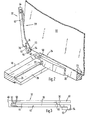
- Fig. 1 shows a card frame, which consists of two die-cast metal side plates 10. These side panels 10 are preferably, but not necessarily, of identical design.
- the side plates 10 have front mounting flanges 12 which are integrally formed. Using screws, not shown, the. inserted through the holes 14 in the front mounting flanges 12, the card frame (or the base) can be installed in a frame or other housing in a known manner.
- the side plates 10 are arranged in vertical planes and connected to one another by means of a plurality of horizontally directed cross struts which are fastened to the side plates. Only an upper front cross strut 16 and a lower front cross strut 18 are shown in FIG. 1. Their design is somewhat simplified for the sake of simplicity.
- the card frame contains upper and lower rear cross struts.
- a large number of card guides have longitudinal channels that are open at the top. The channels are defined by the side walls 23 and extend from the front lower cross strut to the rear lower cross strut. Such a card guide is identified in FIG. 2 by the reference number 20.
- the same card guides with channels open downwards are attached between the front upper cross strut and the rear upper cross strut.
- the card guides attached to the upper cross struts and to the lower cross struts are fixed in vertical, spaced-apart pairs in order to receive cards equipped with electrical circuits in a known manner.
- the upper cross struts and the upper card guides can be substantially the same as the lower cross struts and the lower card guides, except for their orientation, so that only the lower cross struts and lower card guides need to be described.
- the lower and upper cross braces do not necessarily have to be attached to the lower and upper ends of the card frame. It is sufficient if the upper cross struts are closer to the upper end. of the card frame are attached as the lower cross struts. 1 is constructed as described in British patent application no. 81 19 943 is described.
- each end of the card guide 20 is held in a groove 25 of the cross strut 18 by means of resilient extensions 22 of a nose 24 of the card guide 20.
- the nose 24 is held at a desired location along the length of the cross member 18 by means of a receptacle 26 (Fig. 4) in the underside of the nose 24 which receives a selected approach from a plurality of spaced approaches. These approaches are arranged at regular intervals with a desired division along the surface 28 of the cross strut 18.
- the other end of the card guide 20 is provided with a similar nose 24 and held in the same way on the rear lower cross strut.
- the upper card guides are held in the same way on the upper cross struts. The entire facility is structured as described in British patent application no. 81 19 939 is described.
- a card 30 with an electrical circuit can also be seen in FIG. 2, which is partially inserted into the card frame.
- the lower edge of the card 30 is inserted into the lower card guide 20 and the upper edge is held in the same way in the channel of the associated upper card guide.
- the card 30 carries a connector strip which, when the card 30 is fully inserted, is inserted in a known manner into a socket strip which is located on the back of the card frame, e.g. between the rear cross struts or between other cross struts provided for this purpose.
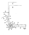
- a two-armed lever 32 which can be formed as a one-piece plastic part, is rotatably fastened in the region of the lower front corner of the card 30 by means of a pin 34, which is fixed in the card 30 and extends from both surfaces of the card 30 into an arc Extends slots 36 which are made in the two upstanding side walls 38 of the lever 32.
- This pivot bearing determines a first relatively short lever arm 40 and a second relatively long lever arm 42.
- the upstanding side walls 38 are connected to one another by means of a web 44 along the lever arm 42.
- the web 44 ends with an edge 46 in the vicinity of the slots 36, a starting position of the lever 32 being defined by the stop of the edge 46 on the front edge of the card 30, as shown in FIG. 2.
- the side walls 38 are to be understood with parts 50 of reduced wall thickness and are therefore correspondingly elastic and deflectable.
- the elasticity is preferably given by the lever 32 molded entirely from elastic plastic.
- the mutually facing surfaces of the parts 50 are provided with lugs 52.
- one of the side walls 38 is provided with a configuration 53 which essentially forms the head of a hook or wrench.
- the design 53 has a hook or claw 54 and a heel 56.
- the hook 54 can be engaged with a receptacle 58 in the nose 24 of the card guide 20.
- the heel 56 can be operatively connected to an end surface 60 of the nose 24.
- the device just described with reference to FIGS. 2 and 3 can be used to insert the cables, i.e. to carry out the last stage of the insertion process and to establish the connection between the plug strip and the socket strip, to press in the card with the lever actuation and to apply the insertion force for the plug strip / socket strip combination in a precisely defined manner and to pull the card out, i.e. to loosen the connection between the connector strip and the socket strip.
- the lever actuation again applies the force required to separate the connector strip and the socket connector strip in a predetermined manner.
- the device also serves to hold the fully inserted card. The operation of the device for performing these three functions will now be explained in more detail with reference to FIGS. 4 to 8.
- Fig. 4 shows the device in a position which it occupies when the card has been pushed into the card frame for most of the way, but the insertion process has not yet begun.
- the lever 32 assumes the starting position described, in which the pin 34 abuts the upper end of the slots 36.
- the angular position of the lever 32 is determined by the relative position of the edge 46 of the web 44 and the pin 34.
- heel 56 abuts front surface 60 of tab 24, as shown in FIG. 5.
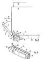
- the lever 32 begins to rotate in the direction of the arrow 64 according to FIG. 5 and the hook 54 is inserted into the receptacle 58.
- the pin 34 moves downward in the slots 36.
- the spacing of the tabs 52 (FIG. 3) of the parts 50 of the side walls 38 is slightly less than the thickness of the card 30. Since the parts 50 of the side walls 38 are elastic, they are articulated so that the card 30 is clamped between the tabs . This clamping force must be overcome when the lever 32 is pivoted in the opposite direction so far away from the card 30 that the hook 54 and the receptacle 58 disengage and the card 30 can be pulled out. The clamping force thus holds the card against unintentional release from the inserted end position.
- lever 32 is manually rotated in the opposite direction, as shown by arrow 66 in FIG. 7.
- the hook 54 is disengaged from the receptacle 58 and the extraction process is released.
- the heel 56 is pressed against the front surface 60 of the nose 24 of the card guide 20.
- the lever is actuated via the pin 34, a pull-out force is exerted on the card 30 with considerable mechanical advantage, which force acts in the direction of the arrow 68 in FIG. 7.
- the card 30 is pulled out fluently and in a predetermined manner and the connection between the plug strip and the socket strip is broken.
- FIG. 8 shows the position in which the pull-out process has ended and the lever 32 has returned to the vicinity of its initial position according to FIG. 5.
- the hook and heel configuration 53 at the free end of the lever arm 40 of the lever 32 can also be doubled, so that an identical configuration is arranged on each side of the card 30.
- This configuration has the advantage that on the pin 34 during insertion and. Extraction process the same forces are exerted on both sides. As a result, the forces are reduced to a minimum, which could cause the card 30 to jam and jam, or a movement of the lever 32 to break the operative connection with the card 30.
- the heels 56 of the two configurations 53 work together with the front surface 60 of the nose 24 of the card guide 20.
- the receptacle 58 for the engagement of the hook 54 is replaced by a pair of receptacles on both sides of the card 30.
- the single receptacle 58 can be replaced by the pair of receptacles 58 ′, which are designed as cutouts or slots in the side walls 23 of the card guide 20.
- the two configurations 53 must be closer in this case be arranged on the card 30 than in the exemplary embodiment with only a single configuration 53.
- the configurations 53 can be aligned with the side walls 38 or formed by the end parts thereof.
- the lever 32 can be thinner than in the exemplary embodiment according to FIGS. 2 and 3.
Applications Claiming Priority (2)
| Application Number | Priority Date | Filing Date | Title |
|---|---|---|---|
| GB8211565 | 1982-04-21 | ||
| GB8211565 | 1982-04-21 |
Publications (1)
| Publication Number | Publication Date |
|---|---|
| EP0097228A1 true EP0097228A1 (fr) | 1984-01-04 |
Family
ID=10529844
Family Applications (1)
| Application Number | Title | Priority Date | Filing Date |
|---|---|---|---|
| EP83103338A Withdrawn EP0097228A1 (fr) | 1982-04-21 | 1983-04-06 | Mécanisme d'insertion et d'extraction pour cartes à modules électriques munies de connecteurs embrochables |
Country Status (4)
| Country | Link |
|---|---|
| US (1) | US4511199A (fr) |
| EP (1) | EP0097228A1 (fr) |
| JP (1) | JPS5916797A (fr) |
| AU (1) | AU1362483A (fr) |
Cited By (6)
| Publication number | Priority date | Publication date | Assignee | Title |
|---|---|---|---|---|
| WO1985005243A1 (fr) * | 1984-04-30 | 1985-11-21 | American Telephone & Telegraph Company | Interrupteur/verrou combine pour controler un module de circuit/la mise sous tension tout en fixant le module au boitier de support |
| EP0166475A2 (fr) * | 1984-05-26 | 1986-01-02 | Philips Patentverwaltung GmbH | Pièce d'insertion pour un bâti de télécommunication |
| DE3437407A1 (de) * | 1984-10-12 | 1986-04-17 | Heckler & Koch Maschinen- und Anlagenbau GmbH, 7230 Schramberg | Griff fuer eine leiterplatte |
| EP0305681A1 (fr) * | 1987-09-01 | 1989-03-08 | Elma Electronic Ag | Manette basculante |
| US5293303A (en) * | 1991-12-11 | 1994-03-08 | Bicc Public Limited Company | Circuit board injector/ejector device for a circuit board enclosure |
| EP0923279A2 (fr) * | 1997-12-11 | 1999-06-16 | Schroff GmbH | Dispositif de retenue d'une carte électronique |
Families Citing this family (9)
| Publication number | Priority date | Publication date | Assignee | Title |
|---|---|---|---|---|
| US4857000A (en) * | 1988-02-16 | 1989-08-15 | Tektronix, Inc. | Circuit board ejector/guide |
| ES2014614A6 (es) | 1989-05-10 | 1990-07-16 | Telefonica Nacional Espana Co | Caratula apantallada con mecanismo de extraccion-retencion. |
| US6267609B1 (en) | 1998-09-29 | 2001-07-31 | The Whitaker Corporation | Ejection mechanism |
| US6396703B1 (en) * | 2001-07-30 | 2002-05-28 | Hewlett-Packard Company | Ejection mechanism for a riser card |
| ATE394912T1 (de) * | 2004-03-19 | 2008-05-15 | Elma Electronic Ag | Ein- und aushebevorrichtung für steckbaugruppen |
| KR101281909B1 (ko) * | 2006-06-30 | 2013-07-03 | 엘지디스플레이 주식회사 | 박막 증착 장치 |
| US8747132B1 (en) * | 2012-06-28 | 2014-06-10 | Emc Corporation | Printed circuit board injector/ejector mechanism |
| US9060453B2 (en) * | 2013-02-20 | 2015-06-16 | Lenovo Enterprise Solutions (Singapore) Pte. Ltd. | Frame having attachment arms, a latching mechanism and handling levers |
| CN110266979B (zh) * | 2018-03-12 | 2021-09-10 | 鸿富锦精密工业(深圳)有限公司 | 卡合结构及电视机 |
Citations (6)
| Publication number | Priority date | Publication date | Assignee | Title |
|---|---|---|---|---|
| US4002381A (en) * | 1975-07-31 | 1977-01-11 | Bell Telephone Laboratories, Incorporated | Card mounting assembly |
| US4083616A (en) * | 1977-02-07 | 1978-04-11 | Stromberg-Carlson Corporation | Printed wiring board levered inject-eject cam |
| FR2393506A1 (fr) * | 1977-06-03 | 1978-12-29 | Alsthom Cgee | Systeme de poignees pour la manoeuvre de cartes de circuits electriques imprimes |
| US4233646A (en) * | 1979-06-29 | 1980-11-11 | Northern Telecom Limited | Latching lever for printed circuit boards |
| US4241966A (en) * | 1979-04-26 | 1980-12-30 | Thomas & Betts Corporation | Connector with ejector-retainer means |
| US4313150A (en) * | 1979-09-24 | 1982-01-26 | Northern Telecom Limited | Latching lever for printed circuit boards |
Family Cites Families (4)
| Publication number | Priority date | Publication date | Assignee | Title |
|---|---|---|---|---|
| US3476258A (en) * | 1967-05-18 | 1969-11-04 | Friden Inc | Board insertion and extraction system |
| CH523000A (de) * | 1971-05-06 | 1972-05-15 | Inventio Ag | Vorrichtung zum Steckverbinden wenistens einer gedruckten Leiterplatte |
| DE3269161D1 (en) * | 1981-06-29 | 1986-03-27 | Loh Kg Rittal Werk | Card frames |
| ATE12157T1 (de) * | 1981-06-29 | 1985-03-15 | Loh Kg Rittal Werk | Kartenrahmen. |
-
1983
- 1983-04-06 EP EP83103338A patent/EP0097228A1/fr not_active Withdrawn
- 1983-04-18 AU AU13624/83A patent/AU1362483A/en not_active Abandoned
- 1983-04-20 JP JP58068455A patent/JPS5916797A/ja active Pending
- 1983-04-21 US US06/486,992 patent/US4511199A/en not_active Expired - Fee Related
Patent Citations (6)
| Publication number | Priority date | Publication date | Assignee | Title |
|---|---|---|---|---|
| US4002381A (en) * | 1975-07-31 | 1977-01-11 | Bell Telephone Laboratories, Incorporated | Card mounting assembly |
| US4083616A (en) * | 1977-02-07 | 1978-04-11 | Stromberg-Carlson Corporation | Printed wiring board levered inject-eject cam |
| FR2393506A1 (fr) * | 1977-06-03 | 1978-12-29 | Alsthom Cgee | Systeme de poignees pour la manoeuvre de cartes de circuits electriques imprimes |
| US4241966A (en) * | 1979-04-26 | 1980-12-30 | Thomas & Betts Corporation | Connector with ejector-retainer means |
| US4233646A (en) * | 1979-06-29 | 1980-11-11 | Northern Telecom Limited | Latching lever for printed circuit boards |
| US4313150A (en) * | 1979-09-24 | 1982-01-26 | Northern Telecom Limited | Latching lever for printed circuit boards |
Cited By (11)
| Publication number | Priority date | Publication date | Assignee | Title |
|---|---|---|---|---|
| WO1985005243A1 (fr) * | 1984-04-30 | 1985-11-21 | American Telephone & Telegraph Company | Interrupteur/verrou combine pour controler un module de circuit/la mise sous tension tout en fixant le module au boitier de support |
| EP0166475A2 (fr) * | 1984-05-26 | 1986-01-02 | Philips Patentverwaltung GmbH | Pièce d'insertion pour un bâti de télécommunication |
| EP0166475A3 (en) * | 1984-05-26 | 1987-06-16 | Philips Patentverwaltung Gmbh | Insertion piece for a telecommunication frame insertion piece for a telecommunication frame |
| DE3437407A1 (de) * | 1984-10-12 | 1986-04-17 | Heckler & Koch Maschinen- und Anlagenbau GmbH, 7230 Schramberg | Griff fuer eine leiterplatte |
| EP0305681A1 (fr) * | 1987-09-01 | 1989-03-08 | Elma Electronic Ag | Manette basculante |
| CH673187A5 (fr) * | 1987-09-01 | 1990-02-15 | Elma Electronic Ag | |
| US4902239A (en) * | 1987-09-01 | 1990-02-20 | Elma Electronic Ag | Rotatable manipulator for a plug board |
| US5293303A (en) * | 1991-12-11 | 1994-03-08 | Bicc Public Limited Company | Circuit board injector/ejector device for a circuit board enclosure |
| EP0923279A2 (fr) * | 1997-12-11 | 1999-06-16 | Schroff GmbH | Dispositif de retenue d'une carte électronique |
| EP0923279A3 (fr) * | 1997-12-11 | 1999-12-29 | Schroff GmbH | Dispositif de retenue d'une carte électronique |
| US6246585B1 (en) | 1997-12-11 | 2001-06-12 | Schroff Gmbh | Card-holding/locking device for the securing/latching of a printed circuit card/board |
Also Published As
| Publication number | Publication date |
|---|---|
| JPS5916797A (ja) | 1984-01-27 |
| AU1362483A (en) | 1983-10-27 |
| US4511199A (en) | 1985-04-16 |
Similar Documents
| Publication | Publication Date | Title |
|---|---|---|
| DE4423220C2 (de) | Unterbrechungsmechanismus für eine Dunkelstromsicherung | |
| DE19942753C2 (de) | Steckverbindung mit einem Befestigungshebel | |
| DE2463081C2 (de) | Befestigungsvorrichtung für den Druckkopf in einer Thermodruckvorrichtung | |
| EP1335644B1 (fr) | Mécanisme pour l'insertion et l'extraction d'un module enfichable | |
| DE2417284C2 (de) | Rahmen zur Aufnahme von gedruckte Schaltungen aufweisenden Karten | |
| DE2544893A1 (de) | Elektrisches verbindungselement fuer eine klemmverbindung und eine elektrische verbindung | |
| EP0097228A1 (fr) | Mécanisme d'insertion et d'extraction pour cartes à modules électriques munies de connecteurs embrochables | |
| DE2700198A1 (de) | Gehaeuse fuer einen elektrischen verbinder | |
| DE2446081A1 (de) | Elektrische verbinderanordnung | |
| DE3244939C1 (de) | Verriegelbare elektrische Flachsteckbuchse und damit versehener elektrischer Verbinder | |
| DE3049336A1 (de) | Stecker und gegenstecker fuer die verbindung von elektrischen leitungen | |
| DE2614628A1 (de) | Steckkontakt-vorrichtung zum montieren an schalt-karten | |
| DE3605316A1 (de) | Hochpoliger steckverbinder | |
| DE3203925C2 (de) | Vorrichtung mit Zugentlastung zum Halten eines Flachbandkabels mit mindestens einem Steckverbinder | |
| EP0086954B1 (fr) | Outil d'extraction d'un tiroir électronique de son support | |
| DE60118687T2 (de) | Verbinder zur Befestigung auf eine Leiterplatte und Anordnung zur Befestigung eines Verbinders auf eine Leiterplatte | |
| DE2516746A1 (de) | Haltevorrichtung fuer eine auf einer gedruckten leiterplatte senkrecht angeordnete und mit dieser kontaktierten zweiten leiterplatte | |
| DE10121171C2 (de) | Scharnier | |
| EP0305681B1 (fr) | Manette basculante | |
| DE19944085B4 (de) | Steckverbindung mit einem Befestigungshebel | |
| DE2106178C3 (de) | Elektrischer Kontakt | |
| EP0166475B1 (fr) | Pièce d'insertion pour un bâti de télécommunication | |
| DE2714409C3 (de) | Verriegelungsvorrichtung für eine Steckvorrichtung | |
| DE3636088C1 (en) | Device for insertion of an assembly into plug connectors and withdrawal of said assembly from plug connectors | |
| DE2653592C2 (de) | Flachkabel-Anschlußvorrichtung |
Legal Events
| Date | Code | Title | Description |
|---|---|---|---|
| PUAI | Public reference made under article 153(3) epc to a published international application that has entered the european phase |
Free format text: ORIGINAL CODE: 0009012 |
|
| AK | Designated contracting states |
Designated state(s): AT BE CH DE FR GB IT LI NL SE |
|
| STAA | Information on the status of an ep patent application or granted ep patent |
Free format text: STATUS: THE APPLICATION IS DEEMED TO BE WITHDRAWN |
|
| 18D | Application deemed to be withdrawn |
Effective date: 19841214 |
|
| RIN1 | Information on inventor provided before grant (corrected) |
Inventor name: ERLAM, DAVID PAUL Inventor name: CARR, ARTHUR EDGAR |