EP0096884A2 - Radar Doppler à impulsions avec un discriminateur de durée d'impulsions - Google Patents
Radar Doppler à impulsions avec un discriminateur de durée d'impulsions Download PDFInfo
- Publication number
- EP0096884A2 EP0096884A2 EP83105790A EP83105790A EP0096884A2 EP 0096884 A2 EP0096884 A2 EP 0096884A2 EP 83105790 A EP83105790 A EP 83105790A EP 83105790 A EP83105790 A EP 83105790A EP 0096884 A2 EP0096884 A2 EP 0096884A2
- Authority
- EP
- European Patent Office
- Prior art keywords
- pulse
- doppler radar
- circuit
- length discriminator
- output
- Prior art date
- Legal status (The legal status is an assumption and is not a legal conclusion. Google has not performed a legal analysis and makes no representation as to the accuracy of the status listed.)
- Granted
Links
- 238000001514 detection method Methods 0.000 claims abstract description 15
- 230000001629 suppression Effects 0.000 claims description 9
- 230000015572 biosynthetic process Effects 0.000 claims description 2
- 238000011144 upstream manufacturing Methods 0.000 claims 1
- 230000001360 synchronised effect Effects 0.000 abstract description 2
- 238000002592 echocardiography Methods 0.000 description 4
- 238000011156 evaluation Methods 0.000 description 3
- 238000009751 slip forming Methods 0.000 description 2
- 241000881711 Acipenser sturio Species 0.000 description 1
- 230000005540 biological transmission Effects 0.000 description 1
- 230000003111 delayed effect Effects 0.000 description 1
- 230000001419 dependent effect Effects 0.000 description 1
- 238000010586 diagram Methods 0.000 description 1
- 238000005070 sampling Methods 0.000 description 1
- 230000008054 signal transmission Effects 0.000 description 1
Images

Classifications
-
- G—PHYSICS
- G01—MEASURING; TESTING
- G01S—RADIO DIRECTION-FINDING; RADIO NAVIGATION; DETERMINING DISTANCE OR VELOCITY BY USE OF RADIO WAVES; LOCATING OR PRESENCE-DETECTING BY USE OF THE REFLECTION OR RERADIATION OF RADIO WAVES; ANALOGOUS ARRANGEMENTS USING OTHER WAVES
- G01S7/00—Details of systems according to groups G01S13/00, G01S15/00, G01S17/00
- G01S7/02—Details of systems according to groups G01S13/00, G01S15/00, G01S17/00 of systems according to group G01S13/00
- G01S7/28—Details of pulse systems
- G01S7/285—Receivers
- G01S7/292—Extracting wanted echo-signals
- G01S7/2921—Extracting wanted echo-signals based on data belonging to one radar period
Definitions
- the invention relates to a pulse Doppler radar device with a pulse length discriminator, a circuit arrangement for fixed character suppression and with a post-integration circuit arranged between the fixed character suppression circuit and the pulse length discriminator.
- scarf CFAR When evaluating radar echo signals, it is necessary to keep the number of false reports constant, regardless of the type of influencing of the receiver, to a predetermined value. To suppress external noise caused by continuous jamming, it is known so-called scarf CFAR -. To use obligations. It is also known to suppress synchronous pulse interferers (intermittent line interferers or noise interferers), which occupy several distance channels, using a pulse length discriminator (DE-OS 28 23419) Criterion for the beginning or end of a flying object or interference signals are formed. If the maximum pulse length specified for flying objects is exceeded, the received signal is interpreted as an interference signal and can be suppressed. Flying object signals covered by interference signals, the amplitude of which is greater than that of the interference signal, are recognized. Ahead is requisite for the intended function of the pulse length discriminator that the amplitudes of sturgeon - and superimposed flying object signals remain unchanged in the signal evaluation before the pulse length discriminator.
- Short single impulses that can have different causes e.g. Movement signal echoes from overrange when using a pulse repetition time that changes from transmit pulse to transmit pulse are not suppressed by the pulse length discriminator.
- the invention has for its object to extend the suppression of interference in signal processing with pulse length discriminator to disturbing individual pulses. According to the invention, this object is achieved in that a controllable switch is arranged in the signal processing branch between the pulse length discriminator and a display device and in that the video signals are fed to a circuit arrangement for single pulse detection via a branch of the signal processing path from the input of the post-integration circuit Switch at the output of the pulse length discriminator controls.
- the single pulse detection takes place in a circuit by forming the difference of the signal amplitudes at the output of the rectifier and at the output of the post-integration circuit and by comparing the difference with a predetermined signal-dependent value.
- This comparison value is a from all signals offered to the radar receiver, for example target echo signals, interference pulses, target echoes with superimposed interference pulses, a normalized target amplitude curve, the energy and amplitude curve of which corresponds approximately to the smallest detectable target.
- a pulse Doppler radar device of a known type with an antenna 1 is equipped on the input side with a transmit / receive switch 2 and a transmit oscillator 3.
- the changeover of the transmit / receive switch 2 is carried out by a clock generator 4.
- the input signal reaches a mixer stage 5, the local oscillator of which is designated by 6.
- the demodulated received signals are fed to a moving character filter 7 (MTI filter) which has a larger number of distance channels.
- the moving character filter suppresses echo signals that come from fixed characters, while moving character echo signals are transmitted virtually undamped. It can be expedient to carry out the signal processing in digital form, that is to say after the mixing stage 5, one indicated here by dashed lines Switch on analog-digital converter 8.
- the essential circuit parts are a controllable switch 12, which is inserted between the pulse length discriminator 10 and the display device 11 in such a way that it can interrupt the transmission path to the display device 11, and a circuit branch branched off from the signal processing path at the input of the integrator 9 and which is another Post-integration circuit 13 and a circuit for single pulse detection contains.
- These circuit parts, together with a video threshold 19 and a control logic 20, which are located at the output of the single pulse detection 14, provide the criterion (H or L signal) for the actuation of the switch 12 in the presence of a disturbing one. Single pulse.
- a single pulse not suppressed in the pulse length discriminator 10 cannot reach the display device 11, since the single pulse detection 22 previously opened the controllable switch 12.
- the switching criterion is formed in the single pulse detection 22 in such a way that in each distance channel the difference between the signal amplitude at the output of the rectifier 8 and the signal amplitude at the output of the post-integration circuit 13 is continuously formed.
- this value is formed from all signals offered to the radar receiver, for example target echoes, interference pulses, target echoes with superimposed interference pulses as a standardized target amplitude value, the energy of which corresponds approximately to the smallest detectable target. If the difference value at the output of the subtractor exceeds the predetermined value ⁇ A, then there is an interference pulse which causes the comparator 17 to emit a signal which controls the switch 18.
- the input of the post-integration circuit 13 is separated from the rectifier 8 and at the same time the switch 18 connects the input and
- the adder 21 has the task of adding a value ⁇ A 'to the feedback output signal of the post-integration, which corresponds, for example, approximately to the normalized signal amplitude.
- a default value ⁇ A "forms the input signal of the post-integration circuit 13, which corresponds, for example, to the smallest detectable movement signal.
- the normalized signal amplitude value ⁇ A which leads to the detection of the interference pulse in the comparator 17, does not have to have the same size as the value ⁇ A 'added in the adder 21 to the output signal of the post-integration circuit 13 delayed by a reception period.
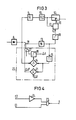
- the circuit of the control logic 20 is shown in FIG. 4.
- the two inputs E1 and E2 are connected to the output of the pulse length discriminator 10 and a video threshold 19.
- the output signal of the pulse length discriminator 10 is direct via the input E1 and the output signal of the video threshold 19 fed to an NAND gate 23 via an inverter 24.
- Output A supplies the control signal for switch 12.
- the function of the control logic is explained in more detail below on the basis of a consideration of various signals offered to the radar receiver.
- the echo signal of a target, a PLD interferer, a PLD interferer with superimposed target echo and finally a single pulse are considered in succession. It can be seen that the control signal "L" is only generated in the case of "single pulse". In this case, the PLD path is interrupted, so the individual pulses do not reach the display device 11.
Landscapes
- Engineering & Computer Science (AREA)
- Radar, Positioning & Navigation (AREA)
- Remote Sensing (AREA)
- Computer Networks & Wireless Communication (AREA)
- Physics & Mathematics (AREA)
- General Physics & Mathematics (AREA)
- Radar Systems Or Details Thereof (AREA)
Applications Claiming Priority (2)
| Application Number | Priority Date | Filing Date | Title |
|---|---|---|---|
| DE19823222474 DE3222474A1 (de) | 1982-06-15 | 1982-06-15 | Puls-doppler-radargeraet mit einem pulslaengen-diskriminator |
| DE3222474 | 1982-06-15 |
Publications (3)
| Publication Number | Publication Date |
|---|---|
| EP0096884A2 true EP0096884A2 (fr) | 1983-12-28 |
| EP0096884A3 EP0096884A3 (en) | 1984-07-18 |
| EP0096884B1 EP0096884B1 (fr) | 1988-11-09 |
Family
ID=6166106
Family Applications (1)
| Application Number | Title | Priority Date | Filing Date |
|---|---|---|---|
| EP19830105790 Expired EP0096884B1 (fr) | 1982-06-15 | 1983-06-13 | Radar Doppler à impulsions avec un discriminateur de durée d'impulsions |
Country Status (2)
| Country | Link |
|---|---|
| EP (1) | EP0096884B1 (fr) |
| DE (1) | DE3222474A1 (fr) |
Family Cites Families (12)
| Publication number | Priority date | Publication date | Assignee | Title |
|---|---|---|---|---|
| BE563351A (fr) * | 1956-12-20 | |||
| US3365718A (en) * | 1965-08-31 | 1968-01-23 | Philips Corp | Device for disturbance suppression in a radar equipment |
| GB1291255A (en) * | 1969-01-24 | 1972-10-04 | Marconi Co Ltd | Improvements in or relating to radars |
| NL6908606A (fr) * | 1969-06-06 | 1970-12-08 | ||
| US4122452A (en) * | 1974-03-12 | 1978-10-24 | Sanders Associates, Inc. | Jamming signal cancellation system |
| US4068233A (en) * | 1976-08-13 | 1978-01-10 | Raytheon Company | Radar system having interference rejection |
| DE2807205C2 (de) * | 1978-02-20 | 1985-04-04 | Siemens AG, 1000 Berlin und 8000 München | Schaltungsanordnung zur Erzielung einer konstanten Falschsignalrate |
| DE2823419A1 (de) * | 1978-05-29 | 1979-12-06 | Siemens Ag | Schaltungsanordnung zur unterdrueckung von stoersignalen in puls-doppler-radarempfaengern |
| DE2840938A1 (de) * | 1978-09-20 | 1980-03-27 | Siemens Ag | Puls-doppler-radarempfaenger mit mti- filter und stoerungsunterdrueckungsschaltungen |
| DE2939512C3 (de) * | 1979-09-28 | 1982-02-25 | Siemens AG, 1000 Berlin und 8000 München | Schaltungsanordnung zur Nebenzipfelunterdrückung in Radargeräten |
| DE3012036C2 (de) * | 1980-03-28 | 1982-06-24 | Siemens AG, 1000 Berlin und 8000 München | Puls-Doppler-Radar mit einer CFAR-Schwelle |
| FR2512210A1 (fr) * | 1981-08-28 | 1983-03-04 | Thomson Csf | Dispositif d'elimination des echos mobiles de ne trace et des echos parasites dans un radar |
-
1982
- 1982-06-15 DE DE19823222474 patent/DE3222474A1/de not_active Withdrawn
-
1983
- 1983-06-13 EP EP19830105790 patent/EP0096884B1/fr not_active Expired
Also Published As
| Publication number | Publication date |
|---|---|
| DE3222474A1 (de) | 1983-12-15 |
| EP0096884A3 (en) | 1984-07-18 |
| EP0096884B1 (fr) | 1988-11-09 |
Similar Documents
| Publication | Publication Date | Title |
|---|---|---|
| DE3640449C1 (de) | Einrichtung zum Bestimmen der Entfernung zwischen zwei Objekten,insbesondere zwei Kraftfahrzeugen | |
| DE2749497C2 (fr) | ||
| DE1791098C3 (de) | Impulsradargerät mit Nahecho/Fernecho-Unterscheidung durch Impulsintervallwechsel | |
| DE69026998T2 (de) | Bistatischer Radarzielsucher mit Entfernungsauftastschaltung | |
| DE69118247T2 (de) | Radargerät mit Störungsindikator und Empfangsvorrichtung mit Störungsindikator | |
| DE3782856T2 (de) | Radar, geschuetzt gegen regenechos und verfahren zum schutz eines radars gegen regenechos. | |
| EP0096883B1 (fr) | Radar Doppler à impulsions avec un discriminateur de durée d'impulsions | |
| DE2546615A1 (de) | Stoerfleckfilter fuer ein puls- doppler-radargeraet | |
| DE2155074C3 (de) | Schaltungsanordnung zur Unterdrückung länger als die Nutzimpulse dauernder, insbesondere gewobbelter, Störsignale für einen Puls-Radarempfänger | |
| DE602004005453T2 (de) | Radar-antischwundsysteme und -verfahren | |
| EP0096884A2 (fr) | Radar Doppler à impulsions avec un discriminateur de durée d'impulsions | |
| DE1124103B (de) | Impulsgetastetes Radargeraet mit Unterdrueckung von Stoerzielanzeigen | |
| DE2157342A1 (de) | Signalverarbeitungseinrichtung, insbesondere für Dopplerradarsysteme | |
| DE69634188T2 (de) | Radar System | |
| DE1591334C1 (de) | Richtungsempfindlich entfernungsmessender,nichtkohaerenter Impulsecho-Ortungsempfaenger mit abschaltbarer Festzeichenunterdrueckung | |
| DE2833023A1 (de) | Verfahren und schaltung zur entfernungsmessung bei luftfahrzeugen mittels eines tacan-systems | |
| DE2840938A1 (de) | Puls-doppler-radarempfaenger mit mti- filter und stoerungsunterdrueckungsschaltungen | |
| DE2325364A1 (de) | Anordnung zum entdecken eines schwachen nutzsignals in rausch- oder stoersignalen | |
| DE2159106C1 (de) | Puls-Radarempfänger mit Unterdrückung kurzzeitiger Störungen durch Vergleich aufeinanderfolgender Zielamplitudenwerte | |
| DE2833065C2 (de) | Schaltungsanordnung zur Unterdrückung störender Empfangssignale für einen Puls-Doppler-Radarempfänger | |
| DE2230823C3 (de) | Pulsdoppler-Radargerät mit kohärenter Mischung | |
| DE2540584A1 (de) | Puls-doppler-radargeraet mit variabler pulsfrequenz | |
| DE1213495B (de) | Anordnung zur Beseitigung der Echos ortsfester Objekte in einem Impulsradargeraet | |
| DE2500877C3 (de) | Anordnung zur Unterdrückung von Störimpulsen in einem Impulsdopplerradarempfänger | |
| DE2641689C2 (de) | Pulsradargerät mit Einrichtungen zur Integration der Empfangssignale |
Legal Events
| Date | Code | Title | Description |
|---|---|---|---|
| PUAI | Public reference made under article 153(3) epc to a published international application that has entered the european phase |
Free format text: ORIGINAL CODE: 0009012 |
|
| AK | Designated contracting states |
Designated state(s): FR GB IT NL |
|
| PUAL | Search report despatched |
Free format text: ORIGINAL CODE: 0009013 |
|
| AK | Designated contracting states |
Designated state(s): FR GB IT NL |
|
| 17P | Request for examination filed |
Effective date: 19841221 |
|
| 17Q | First examination report despatched |
Effective date: 19860929 |
|
| D17Q | First examination report despatched (deleted) | ||
| GRAA | (expected) grant |
Free format text: ORIGINAL CODE: 0009210 |
|
| AK | Designated contracting states |
Kind code of ref document: B1 Designated state(s): FR GB IT NL |
|
| GBT | Gb: translation of ep patent filed (gb section 77(6)(a)/1977) | ||
| ET | Fr: translation filed | ||
| ITF | It: translation for a ep patent filed | ||
| PG25 | Lapsed in a contracting state [announced via postgrant information from national office to epo] |
Ref country code: GB Effective date: 19890613 |
|
| PLBE | No opposition filed within time limit |
Free format text: ORIGINAL CODE: 0009261 |
|
| STAA | Information on the status of an ep patent application or granted ep patent |
Free format text: STATUS: NO OPPOSITION FILED WITHIN TIME LIMIT |
|
| 26N | No opposition filed | ||
| PG25 | Lapsed in a contracting state [announced via postgrant information from national office to epo] |
Ref country code: NL Effective date: 19900101 |
|
| GBPC | Gb: european patent ceased through non-payment of renewal fee | ||
| NLV4 | Nl: lapsed or anulled due to non-payment of the annual fee | ||
| PG25 | Lapsed in a contracting state [announced via postgrant information from national office to epo] |
Ref country code: FR Free format text: LAPSE BECAUSE OF NON-PAYMENT OF DUE FEES Effective date: 19900228 |
|
| REG | Reference to a national code |
Ref country code: FR Ref legal event code: ST |