EP0096751B1 - Elektropneumatische Vorsteuerstufe für ein pneumatisches Servoventil - Google Patents
Elektropneumatische Vorsteuerstufe für ein pneumatisches Servoventil Download PDFInfo
- Publication number
- EP0096751B1 EP0096751B1 EP19830104637 EP83104637A EP0096751B1 EP 0096751 B1 EP0096751 B1 EP 0096751B1 EP 19830104637 EP19830104637 EP 19830104637 EP 83104637 A EP83104637 A EP 83104637A EP 0096751 B1 EP0096751 B1 EP 0096751B1
- Authority
- EP
- European Patent Office
- Prior art keywords
- spool
- stage
- plunging
- control
- electropneumatic
- Prior art date
- Legal status (The legal status is an assumption and is not a legal conclusion. Google has not performed a legal analysis and makes no representation as to the accuracy of the status listed.)
- Expired
Links
Images

Classifications
-
- F—MECHANICAL ENGINEERING; LIGHTING; HEATING; WEAPONS; BLASTING
- F16—ENGINEERING ELEMENTS AND UNITS; GENERAL MEASURES FOR PRODUCING AND MAINTAINING EFFECTIVE FUNCTIONING OF MACHINES OR INSTALLATIONS; THERMAL INSULATION IN GENERAL
- F16K—VALVES; TAPS; COCKS; ACTUATING-FLOATS; DEVICES FOR VENTING OR AERATING
- F16K31/00—Actuating devices; Operating means; Releasing devices
- F16K31/12—Actuating devices; Operating means; Releasing devices actuated by fluid
- F16K31/42—Actuating devices; Operating means; Releasing devices actuated by fluid by means of electrically-actuated members in the supply or discharge conduits of the fluid motor
- F16K31/423—Actuating devices; Operating means; Releasing devices actuated by fluid by means of electrically-actuated members in the supply or discharge conduits of the fluid motor the actuated members consisting of multiple way valves
- F16K31/426—Actuating devices; Operating means; Releasing devices actuated by fluid by means of electrically-actuated members in the supply or discharge conduits of the fluid motor the actuated members consisting of multiple way valves the actuated valves being cylindrical sliding valves
-
- F—MECHANICAL ENGINEERING; LIGHTING; HEATING; WEAPONS; BLASTING
- F15—FLUID-PRESSURE ACTUATORS; HYDRAULICS OR PNEUMATICS IN GENERAL
- F15B—SYSTEMS ACTING BY MEANS OF FLUIDS IN GENERAL; FLUID-PRESSURE ACTUATORS, e.g. SERVOMOTORS; DETAILS OF FLUID-PRESSURE SYSTEMS, NOT OTHERWISE PROVIDED FOR
- F15B13/00—Details of servomotor systems ; Valves for servomotor systems
- F15B13/02—Fluid distribution or supply devices characterised by their adaptation to the control of servomotors
- F15B13/04—Fluid distribution or supply devices characterised by their adaptation to the control of servomotors for use with a single servomotor
- F15B13/042—Fluid distribution or supply devices characterised by their adaptation to the control of servomotors for use with a single servomotor operated by fluid pressure
- F15B13/043—Fluid distribution or supply devices characterised by their adaptation to the control of servomotors for use with a single servomotor operated by fluid pressure with electrically-controlled pilot valves
- F15B13/0438—Fluid distribution or supply devices characterised by their adaptation to the control of servomotors for use with a single servomotor operated by fluid pressure with electrically-controlled pilot valves the pilot valves being of the nozzle-flapper type
-
- H—ELECTRICITY
- H01—ELECTRIC ELEMENTS
- H01F—MAGNETS; INDUCTANCES; TRANSFORMERS; SELECTION OF MATERIALS FOR THEIR MAGNETIC PROPERTIES
- H01F7/00—Magnets
- H01F7/06—Electromagnets; Actuators including electromagnets
- H01F7/066—Electromagnets with movable winding
-
- Y—GENERAL TAGGING OF NEW TECHNOLOGICAL DEVELOPMENTS; GENERAL TAGGING OF CROSS-SECTIONAL TECHNOLOGIES SPANNING OVER SEVERAL SECTIONS OF THE IPC; TECHNICAL SUBJECTS COVERED BY FORMER USPC CROSS-REFERENCE ART COLLECTIONS [XRACs] AND DIGESTS
- Y10—TECHNICAL SUBJECTS COVERED BY FORMER USPC
- Y10T—TECHNICAL SUBJECTS COVERED BY FORMER US CLASSIFICATION
- Y10T137/00—Fluid handling
- Y10T137/8593—Systems
- Y10T137/86493—Multi-way valve unit
- Y10T137/86574—Supply and exhaust
- Y10T137/86582—Pilot-actuated
- Y10T137/86614—Electric
Definitions
- the invention relates to an electropneumatic pilot stage for controlling a pneumatic servo valve for pneumatic drive systems with a nozzle-baffle plate system, the baffle plate of which can be controlled in connection with a plunger coil in the area of a magnetic field due to the input of electrical signals.
- An electro-pneumatic servo valve is a device for controlling an air flow or air pressure through a pneumatic valve main stage in proportion to an input of electrical signals in a so-called electro-pneumatic pilot stage.
- An electric or electronic control system should be preferred because the performance requirements in terms of flexible, dynamic controllability are more manageable and superior to mechanical or purely fluidic systems in many respects.
- the goal with an electropneumatic pilot stage must be to assign a certain definable, corresponding pressure or a volume flow at the outlet of the valve main stage or the pneumatic servo valve to a specific electrical input signal at the pilot stage.
- the electrically controllable valves can be divided into two types, of which one type can be referred to as an electrically directly actuated valve, the second type as an electrically indirectly actuated valve.
- the actuating force for actuating the valve closing element is generated directly by an electromagnet. This means that the maximum controllable passage volumes or pressures are directly dependent on the actuating force available on the part of the magnet. In order to apply the latter, large-volume electromagnets with coils of equal size are required. which in comparison to the pneumatic valve main stage are not inferior in size and weight with known servo valves.
- the electrical power consumption in such types of servo valves is of an order of magnitude that can only be achieved by electronic control systems, for example, only through the interposition of complex amplification circuits.
- Servo valves in which the geometric data of the pilot control stage and valve main stage are approximately the same size, are therefore not suitable for integration into pneumatic drive systems.
- the large masses to be moved prevent the desired dynamic behavior for actuators.
- the cut-off frequency for example, remains far below the values required in application for the precise and fast control of actuators in handling technology.
- the much too high electrical power consumption, which generates considerable heat radiation through conversion, places limits on use, so that either additional cooling or reduced power consumption must be made a requirement. From GB-A-1 125102 and DE-A-2 936 425 servo valves are known in which the working medium flows around the electromagnet and is cooled.
- the second type mentioned referred to as an electrically indirectly actuable valve, is in particular an electropneumatic pilot control stage, consisting of a so-called pilot valve which is actuated by the electromagnet and adjusts the main valve by pressurizing the control piston.
- the advantage of the electrically controllable pilot valve is that the controllable pressures or passage volumes are independent of the actuating force of the magnet. The necessary electrical power consumption is only determined by the pilot valve or the coil that sets the latter.
- the solution with the pilot valve represents a somewhat more complex concept, it paves the way for solving the largely priority problems with regard to miniaturization and improvement of the dynamic behavior.
- a first difficulty that still has to be overcome is the design of a suitable moving coil.
- the object of the invention is to create a simple, small, electropneumatic pilot control stage for controlling a pneumatic servo valve, which is suitable for integration into pneumatic drives due to the smallest possible dimensions with low power consumption and due to an optimal, dynamic behavior.
- the solution to the problem of creating an electropneumatic pilot stage with a nozzle-Prattptatte-Systetn for controlling a pneumatic servo valve is characterized in that in a diaphragm spring washer as a carrier element of a plunger coil and in the front flange of the coil body in the axial direction for the arrangement of the coil and concentrically around a central Baffle plate openings are arranged, and that in the region of a cylindrical cavity, which is formed by a peripheral, ring-shaped magnet and a centrally immersed anchor pin of a T-shaped armature, exhaust air ducts leading to the outside of the armature are provided on the front side of the armature, in such a way that a from a measuring nozzle into the Airflow flowing out of the pilot control stage is guided past the cylindrical outer and inner surfaces of the coil through the magnetic air gap, so that the coil is permanently cooled by the servo valve's own working medium.
- the air flow permanently flowing out of the measuring nozzle ensures a considerably improved heat dissipation, by means of which the current density can be significantly increased. Due to a correspondingly distributed arrangement of the openings in the diaphragm spring washer and possibly the flange of the coil body, the permanently effective air flow is inevitably and evenly distributed past the cylindrical outer and inner sides of the moving coil.
- the air heated by heat extraction from the coil is discharged into the atmosphere through the cylindrical cavity between the ring-shaped magnet and the armature pin and further through several exhaust air channels in the end face of the pilot stage.
- the pilot stage Due to the design of the pilot stage and the measures to control the exhaust air flow from the measuring nozzle, it is possible to achieve a very effective cooling effect in the area of the heat radiation zone in the pilot stage by using the valve's own working medium. Without the expense of additional artificial cooling, the unchanged valve performance can be achieved through reduced power consumption.
- the current density can be increased by the effective heat extraction, which means that the moving coil can be made smaller with the same control output. This advantage not least benefits improved dynamics due to the reduced moving masses of the moving coil.
- the pilot measures for the indirectly actuated pneumatic servo valve can be geometrically built considerably smaller by the measures described, and the miniaturization achieved in this way additionally creates good conditions for the integration of the servo valve described in pneumatic drives.
- An embodiment of the electro-pneumatic servo valve according to the above. Art consists of a pilot stage 1 and a main valve stage 2, the devices of the pilot stage 1 in a housing 3 and the facilities of the main valve stage 2 in a separate housing 4.
- a permanent magnet 5, an armature 6, and a plunger coil 7 with a specially designed coil former 8 with an integrated baffle plate 9 are accommodated in the housing 3 as devices of the pilot stage 1 (FIG. 1).
- the bobbin 8 with the baffle plate 9 is by a Membrane spring washer 10 carried by the baffle plate 9 is plugged into a corresponding bore 11 in the membrane spring washer 10, for example by a press fit or in a positive manner.
- an inwardly projecting collar 13 is provided in the cylindrical cavity 14 of the pilot stage 1 near the front side 12 facing the valve main stage 2.
- This collar 13 serves to support an annular pole piece 16 inserted into the cylindrical cavity 14 from the initially open end face 15.
- the next part is an annular permanent magnet 5, which is also annular, and finally an armature 6, shown in a T-shaped section in the sectional view, the anchor pin 18 in the installed position terminates approximately with the lower edge of the pole piece 16.
- An edge 20 of the housing 3 protruding beyond the outwardly directed armature end face 19 is flanged inward and thus holds the parts inserted into the housing 3 in an unchangeably defined position with respect to the other functional levels otherwise determined by the design of the pilot control stage 1.
- One of the above-mentioned functional levels is formed by the positioning of a surface 23 of a baffle plate 9 which interacts with an outlet opening 21 of a control air measuring nozzle 22.
- the baffle plate 9 in a design form shown in FIG. 1 is part of a one-piece coil former 8 and is as already mentioned, received in the central bore 11 of the disk-shaped diaphragm spring washer 10.
- the diaphragm spring washer 10 is held in a recess 26 in the inner wall of the housing 3.
- the currentless starting position of the moving coil 7 in the air gap 17 of the magnetic field between the pole shoe 16 and the armature pin 18 is thus determined and, at the same time, the position of the effective surface 23 of the baffle plate 9 relative to the housing 3 is defined.
- a fine thread 24 is provided on a collar-shaped part of the outer wall of the housing of the pilot stage 1 Can screw in the fine thread bore 25 arranged at the end face in the housing 4 of the valve main stage 2. Due to the property of a small pitch of the threads in a fine thread, the pilot stage 1 and here in particular the diaphragm spring washer 10 positioned in firm connection to the housing 3 with the baffle plate 9 can be passed to the outlet opening 21 of the measuring nozzle 22 with a correspondingly high degree of accuracy and with a correspondingly high degree of accuracy bring up.
- the measuring nozzle 22 is provided in an exchangeable nozzle disk 27 which can be inserted into the housing 4 in contact with a cylindrical control bushing 28.
- an elastomeric sealing element 31 is provided as a flexible intermediate layer in an embodiment according to FIGS. And 2 between the nozzle disk 27 and the lower housing edge 30 of the pilot stage 1, which element can be adjusted with an absolute sealing effect the position of the baffle plate 9 in the pilot stage 1 to the measuring nozzle 22 in the main valve stage 2 in the range of a selectable operating point.
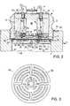
- the diaphragm spring washer 10 which is clamped peripherally in the assembled state between the pilot stage 1 and the nozzle disk 27 of the valve main stage 2 as the carrier element of a plunger coil 7, has openings 58 in the resilient intermediate zone, which on the one hand design the spring arms and on the other hand the distributed guidance of an air flow 64 serve the measuring nozzle 22 through the magnetic air gap 66, 67 past the cylindrical outer and inner surfaces of the moving coil 7.
- further openings 61 are provided in the coil body 8 according to FIG. 1 in the end flange 65, which lead the air flow 64 through the coil core.
- a pilot stage 1 according to FIGS.
- openings 62 are provided concentrically around a baffle plate surface 23 of the diaphragm spring washer 10, via which a portion of the air flow flowing out of the measuring nozzle 22 64 is passed through an open flange 65 and further through the inner air gap 67 between the coil former 8 and the armature pin 18.
- axially protruding knobs 68 are provided on the latter, by means of which the coil former 8 can be plugged into correspondingly arranged slots 69 in the diaphragm spring washer 10.
- the exhaust air ducts 63 are dimensioned in the passage cross section such that they do not constitute a retrospective throttling of the control air flow 64 even with the maximum exhaust air flow.
- Protective sleeves 71 for example made of an insulation material, are inserted into the exhaust air channels 63, through which additional sleeves. Lich to derive the drain, the connecting lines 72 to the moving coil 7 are guided freely movable.
- the pre-control stage 1 described above is part of an indirectly controllable, pneumatic servo valve, the pneumatic valve main stage 2 of which is composed as follows:
- a cylindrical bore 37 is provided in the housing 4 of the main valve stage 1, into which the control bushing 28 is inserted.
- the control bushing 28 has outer ring grooves 38, 39, 40 which, in the installed position, are connected to bores 41, 42, 43 for the attachment of connecting lines.
- the position of the control bushing 28 in the bore 37 is secured on the one hand by the support on a closure piece 44 with a central ventilation bore 45, which is axially secured by a spring ring 46 in a groove 47 of the cylindrical bore 37 in the housing 4.
- the control bushing 28 is secured by contact with the nozzle disk 27, which is pressed against the control bushing 28 by the sealing element 31 by the pilot stage 1 screwed inward.
- the outer ring grooves 38, 39, 40 in the control bushing 28 communicate via radial bores 48, 49, 50 with ring grooves 51, 53 in a control piston 54 and an inner ring groove 52 in the control bushing 28.
- the control piston 54 is axially movable in a cylinder bore 59 Control bush 28 stored.
- the control bushing 28 itself is sealed against the housing 4 by means of sealing rings 60.
- the bore 43 (P) serves for the connection of a primary compressed air line.
- the secondary pressure line or working pressure line is connected to the bore 42 (A), the bore 41 (R) finally serves to connect the exhaust air or return line.
- the annular groove 53 which is constantly under the influence of primary pressure, communicates via a control air channel 55, which is created as a central bore in the control piston 54, and via a control air flow restrictor 56 with the control air space 29 at the end of the control piston 54 facing the pilot stage 1.
- the thrust effect on the control piston 54 due to a variably controllable pressure in the control air space 29, a compression spring 57 counteracts, which is supported on the closure piece 44.
- an adjusting screw which is adjustable from the outside and is not shown in detail, can also be provided while maintaining a ventilation hole 45.
- connection line for the primary pressure is applied to the bore 43 (P).
- the medium characterized by overpressure air or another gas can not be effective because of the position of the control piston 54 shown in FIG. 1 in the upper extreme position as a working air flow at the consumer connection at A, since in said position between the annular groove 53, which in itself is constantly with communicates the supply air flow connection at the bore 43, and the consumer connection in A is not a continuous connection.
- valve main stage 2 is set to a maximum cross section of the consumer connection at A in the backflow direction to the connection R.
- This setting is generally retained in the exemplary embodiment shown, as long as the prerequisites for a change in the position of the control piston 54 set by the compression spring 57 are not given by applying supply compressed air.
- a change in the position of the control piston 54 can be achieved if it is ensured that the pressure in the control air space 29 builds up above the control piston 54 to such an extent that it overcomes the restoring force of the compression spring 57 as a positioning force and the control piston 54 according to FIG. shifts down accordingly.
- a necessary transfer of the primary air pressure in the supply connection at P into the control air space 29 takes place via a permanent connection of the bore 43 via the outer ring groove 40 and radial bores 50 in the Control bushing 28 with the annular groove 53, which in turn is connected to the control air space 29 via the control air duct 55 and the control air flow restrictor 56. If you want to set an air flow that can be controlled at the consumer connection in A, this is done by appropriate positioning of the control piston 54.
- a current-proportional control of the plunger 7 takes place on the basis of electrical input current signals , thereby limits or reduces the outflow of control air from the control air space 29 and thus generates in the control air space 29 an effective control pressure of, for example, 1.5 to 6 b on the end face of the control piston 54.
- the control piston 54 is deflected against the compression spring 57 due to this variably adjustable pressure, so that after reaching a certain control piston position with increasing control pressure, an overlap of the annular groove 53 under supply pressure with the inner annular groove 52 and thus with the consumer connection at A, which is also increasingly adjustable in cross section, takes place .
- the connection between the consumer connection at A and the reflux connection in R which was previously set to the maximum flow cross section, is closed. If the signal current for controlling the moving coil 7 is withdrawn, the situation is reversed accordingly; ie the working air flow at the consumer connection A is then throttled accordingly and the connection from P to A is finally closed in the continuation. Then again there is a change in the connection of the consumer connection A to the. Exhaust air or return flow connection in R instead.
- the device shown is a two-stage, indirect valve control which consists of an electropneumatic signal converter or pilot stage 1 and a valve main stage which can be set independently of the load 2 exists.
- pilot control stage 1 as a servo device, it is possible, with small electrical control currents of up to approx. 200 mA, indirectly to control the volume flow of a main valve stage 2 in the order of magnitude of, for example, 500 rpm. to control.
- a very special advantage here is that there is a proportional relationship between the electrical signal current in the moving coil 7 and the volume flow at the consumer output in A.
- the small masses of the servo valve which are moved due to the measures provided in the pilot control stage 1, such as cooling and the resulting reduction in size, are a prerequisite for a rapid implementation.
- the heat removal can also be used to the effect that the dimensions of the moving coil are kept extremely small and correspondingly small, moving masses are achieved.
- An arrangement of the exhaust air ducts 63 above the plunger 7, however, for the discharge of the air flow 64 to the side can take place in each case according to the requirement for a corresponding installation position, without this changing the mode of action of the measures described above.
Landscapes
- Engineering & Computer Science (AREA)
- Physics & Mathematics (AREA)
- General Engineering & Computer Science (AREA)
- Electromagnetism (AREA)
- Mechanical Engineering (AREA)
- Power Engineering (AREA)
- Fluid Mechanics (AREA)
- Supply Devices, Intensifiers, Converters, And Telemotors (AREA)
- Magnetically Actuated Valves (AREA)
- Servomotors (AREA)
Description
- Die Erfindung bezieht sich auf eine elektropneumatische Vorsteuerstufe zur Steuerung eines pneumatischen Servoventils für pneumatische Antriebssysteme mit einem Düse-Prallplatte-System, dessen Prallplatte in Verbindung mit einer Tauchspule im Bereich eines Magnetfeldes aufgrund der Eingabe elektrischer Signale steuerbar ist.
- Ein elektropneumatisches Servoventil ist eine Einrichtung zur Steuerung eines Luftstromes oder Luftdruckes durch eine pneumatische Ventilhauptstufe proportional zu einer Eingabe elektrischer Signale in eine so bezeichnete elektropneumatische Vorsteuerstufe. Einem elektrischen oder elektronischen Steuerungssystem ist der Vorzug zu geben schon deshalb, weil die Leistungsanforderungen in bezug auf eine flexible, dynamische Steuerfähigkeit besser beherrschbar und den mechanischen oder rein fluidischen Systemen in vielen Beziehungen überlegen sind. Das Ziel bei einer elektropneumatischen Vorsteuerstufe muß es sein, einem bestimmten elektrischen Eingangssignal an der Vorsteuerstufe einen eindeutig definierbaren, entsprechenden Druck bzw. einen Volumenstrom am Ausgang der Ventilhauptstufe bzw. des pneumatischen Servoventils zuzuordnen. Um schließlich von einem elektropneumatischen Umformer der bezeichneten Art einen hohen Verstärkungseffekt zu erhalten, hängt davon ab, mit einer möglichst kleinen elektrischen Leistung auf der Eingangsseite des Ventils in proportionaler Abhängigkeit einen möglichst hohen Volumenstrom oder die Wirkung großer Drücke steuerbar zu machen. Will man hierfür die Voraussetzungen schaffen, so sind alle Einflußgrößen in bezug auf die Bauteile und die Kombinationen von Steuerungselementen bei bekannten Ventilen dieser Art zu untersuchen und gegebenenfalls optimal aufeinander abzustimmen. Eine der Hauptkenndaten für einen optimalen Verstärkungseffekt liegt sicherlich in der elektrischen Leistungsaufnahme, die es unter Beibehaltung der pneumatischen Ventilleistung so weit zu reduzieren gilt, daß aufgrund einer verhältnismäßig minimalen elektrischen Leistungsaufnahme entsprechend ausgebildete Ventile auch im Bereich der vielerorts vorgeschriebenen Eigensicherheit oder als computergesteuerte Ventile einsetzbar sind.
- Weiter für den Anwender grundsätzliche Einflußgrößen ergeben sich aus der baulichen Konzeption des elektropneumatischen Servoventils. Hier gilt es insbesondere auf Maßnahmen zu achten, die ohne Verzicht auf einen Teil der Ventilleistung zu einer Miniaturisierung der Baugruppen und hier insbesondere der elektropneumatischen Vorsteuerstufe führen. Eine erste Forderung besteht in der Anwendung von konstruktiven Maßnahmen zur Erzielung möglichst kleiner Baumaße, die einer besseren Integration derart ausgebildeter Servoventile, beispielsweise in Gehäuse pneumatischer Antriebssysteme, dienen. Von sehr großer Bedeutung sind ein geringes Gewicht des Gesamtventils und in diesem Zusammenhang vor allem auch geringe bewegte Massen in der Vorsteuerstufe, das sind Maßnahmen, die insgesamt gesehen zu einer wesentlichen Verbesserung der dynamischen Verhältnisse des Ventils beitragen. In bezug auf die Einflußgrößen nach vorstehender Darlegung lassen sich die elektrisch steuerbaren Ventile in zwei Bauarten unterteilen, wovon eine Bauart aufgrund der Funktionsweise als elektrisch direkt betätigbares Ventil, die zweite Bauart als elektrisch indirekt betätigbares Ventil zu bezeichnen ist. Beim elektrisch direkt betätigbaren Ventil wird die Stellkraft zur Betätigung des Ventilschließelementes direkt von einem Elektromagneten erzeugt. Das bedeutet, die maximal steuerbaren Durchlaßvolumina oder Drücke sind direkt abhängig von der seitens des Magneten verfügbaren Stellkraft. Um letztere aufzubringen, sind großvolumige Elektromagnete mit gleichermaßen großen Spulen erforderlich. die im Vergleich zur pneumatischen Ventilhauptstufe dieser in Baugröße und Gewicht bei bekannten Servoventilen nicht nachstehen. Schließlich bewegt sich die elektrische Leistungsaufnahme bei derartigen Bauformen von Servoventilen in einer Größenordnung, die von elektronischen Steuerungssystemen beispielsweise nur durch Zwischenschaltung von aufwendigen Verstärkungsschaltkreisen erreichbar ist. Servoventile,. bei welchen die geometrischen Daten von Vorsteuerstufe und Ventilhauptstufe etwa gleich groß sind, eignen sich demnach nicht für eine Integration in pneumatische Antriebssysteme. Die großen, zu bewegenden Massen verhindern das für Stellantriebe gewünschte Maß an dynamischem Verhalten. Die Grenzfrequenz beispielsweise bleibt weit unter den Werten, wie sie im Anwendungsfall zur genauen und schnellen Regelung von Stellantrieben in der Handhabungstechnik gefordert sind. Die viel zu hohe elektrische Leistungsaufnahme, die durch Umwandlung eine beträchtliche Wärmeabstrahlung erzeugt, setzt Einsatzgrenzen, so daß entweder zusätzliche Kühlung oder verringerte Leistungsaufnahme zur Bedingung gemacht werden müssen. Aus der GB-A-1 125102 und DE-A-2 936 425 sind Servoventile bekannt, bei denen der Elektromagnet vom Arbeitsmedium umspütt und gekühlt wird.
- Bei der genannten zweiten Bauart, als elektrisch indirekt betätigbares Ventil bezeichnet, handelt es sich insbesondere um eine elektropneumatische Vorsteuerstufe, bestehend aus einem sog. Pilotventil, das durch den Elektromagneten betätigt wird und durch Druckbeaufschlagung des Steuerkolbens das Hauptventil einstellt. Der Vorteil des elektrisch steuerbaren Pilotventils besteht darin, daß die steuerbaren Drücke bzw. Durchlaßvolumina von der Stellkraft des Magneten unabhängig sind. Die notwendige elektrische Leistungsaufnahme wird hierbei nur durch das Pilotventil bzw. der Spule, die letzteres einstellt, bestimmt. Obgleich die Lösung mit dem Pilotventil eine etwas aufwendigere Konzeption darstellt, bereitet sie den Weg zur Lösung der weitgehend vorrangigen Probleme im Hinblick auf eine Miniaturisierung und Verbesserung des dynamischen Verhaltens. Eine erste, noch zu überwindende Schwierigkeit besteht in der Auslegung einer geeigneten Tauchspule. Letztere wird bei einer Vorsteuerstufe der eingangs bezeichneten Art begrenzt einerseits durch die notwendige Kraft der Auslenkung einer Membranfeder und andererseits durch die zulässige Stromdichte in der Tauchspule. Da die Ventilleistung wenigstens unverändert beibehalten werden soll und damit keine Verringerung der Auslenkkraft zugelassen werden kann, ist eine allgemeine Leistungsverbesserung nur noch denkbar durch erhöhte Stromdichte bei einer entsprechend verbesserten Wärmeabfuhr. Diese Überlegung kommt auch der Forderung nach einer geometrisch kleinen Bauweise entgegen und läßt sich insbesondere bei indirekt durch eine elektropneumatische Vorsteuerstufe der eingangs bezeichneten Art steuerbaren Ventilen einführen.
- Demnach besteht die Aufgabe der Erfindung in der Schaffung einer einfachen, kleinen, elektropneumatischen Vorsteuerstufe zur Steuerung eines pneumatischen Servoventils, die sich durch möglichst kleine Abmessungen bei geringer Leistungsaufnahme und durch ein optimales, dynamisches Verhalten für eine Integration in pneumatische Antriebe eignet.
- Die Lösung der Aufgabe zur Schaffung einer elektropneumatischen Vorsteuerstufe mit einem Düse-Prattptatte-Systetn zur Steuerung eines pneumatischen Servoventils ist dadurch gekennzeichnet, daß in einer Membranfederscheibe als Trägerelement einer Tauchspule sowie im stirnseitigen Flansch des Spulenkörpers in Achsrichtung zur Anordnung der Spule und konzentrisch um eine zentrale Prallplattenfläche Durchbrüche angeordnet sind, und daß im Bereich eines zylindrischen Hohlraums, der gebildet wird durch einen peripheren, ringförmigen Magneten und einen zentral eintauchenden Ankerzapfen eines T-förmigen Ankers stirnseitig des Ankers nach außen führende Abluftkanäle vorgesehen sind, dergestalt daß ein aus einer Meßdüse in die Vorsteuerstufe ausströmender Luftstrom durch den magnetischen Luftspalt hindurch an den zylindrischen Außen- und Innenflächen der Spule vorbeigeleitet ist, so daß durch das eigene Arbeitsmedium des Servoventils eine permanente Kühlung der Spule erfolgt.
- Weitere Merkmale zur Ausgestaltung der Erfindung sind in den Unteransprüchen enthalten.
- In vorteilhafter Weise wird mit der im Patentanspruch angegebenen Maßnahme erreicht, daß durch den aus der Meßdüse permanent ausströmenden Luftstrom eine beträchtlich verbesserte Wärmeabfuhr gewährleistet ist, durch welche die Stromdichte wesentlich erhöht werden kann. Durch eine entsprechend verteilte Anordnung der Durchbrüche in der Membranfederscheibe und gegebenenfalls dem Flansch des Spulenkörpers wird der permanent wirksame Luftstrom zwangsläufig und gleichmäßig verteilt an den zylindrischen Außen- und Innenseiten der Tauchspule vorbeigeführt. Die durch Wärmeentzug an der Spule erwärmte Luft wird durch den zylindrischen Hohlraum zwischen dem ringförmigen Magneten und dem Ankerzapfen und weiter durch mehrere Abluftkanäle in der Stirnseite der Vorsteuerstufe in die Atmosphäre abgeführt. Aufgrund des konstruktiven Aufbaus der Vorsteuerstufe und der Maßnahmen zur Lenkung des Abluftstromes aus der Meßdüse gelingt es unter Ausnutzung des ventileigenen Arbeitsmediums einen sehr wirkungsvollen Kühleffekt im Bereich der Wärmeabstrahlzone in der Vorsteuerstufe zu erzielen. Ohne den Aufwand einer zusätzlichen künstlichen Kühlung erreicht man einerseits die unveränderte Ventilleistung über eine reduzierte Leistungsaufnahme. Die Stromdichte kann durch den wirksamen Wärmeentzug erhöht werden, das bedeutet, die Tauchspule kann bei gleicher Steuerleistung kleiner gebaut werden. Dieser Vorteil kommt nicht zuletzt einer verbesserten Dynamik zugute aufgrund der damit verkleinerten bewegten Massen der Tauchspule. Allgemein läßt sich durch die bezeichneten Maßnahmen die Vorsteuerstufe für das indirekt betätigte pneumatische Servoventil geometrisch um ein beträchtliches Maß kleiner bauen, und durch die auf diese Art erreichte Miniaturisierung sind zusätzlich gute Voraussetzungen geschaffen für die Integration des bezeichneten Servoventils in pneumatische Antriebe.
- Ein Ausführungsbeispiel des Gegenstandes der Erfindung ist nachstehend beschrieben und anhand der Zeichnungen gezeigt.
- Es zeigt
- Figur 1 ein Schnittbild eines indirekt betätigten Servoventils, bestehend aus einer elektropneumatischen Vorsteuerstufe und einer Ventilhauptstufe,
- Figur 2 eine elektropneumatische Vorsteuerstufe im Schnitt, bei der eine Membranfederscheibe als Prallplatte dient und gleichzeitig mit Durchbrüchen versehen ist zur Ableitung der Steuerluft zur Kühlung der Tauchspule,
- Figur 3 eine Membranfederscheibe mit konzentrisch zur Lage der Tauchspule angeordneten Durchbrüchen zur Verteilung und Lenkung des Luftstromes aus der Meßdüse in den Wärmeabstrahlbereich der Tauchspule.
- Eine Ausführungsform des elektropneumatischen Servoventils gemäß der vorbeschriebenen . Art besteht aus einer Vorsteuerstufe 1 und einer Ventilhauptstufe 2, wobei die Einrichtungen der Vorsteuerstufe 1 in einem Gehäuse 3 und die Einrichtungen der Ventilhauptstufe 2 in einem separaten Gehäuse 4 untergebracht sind. Als Einrichtungen der Vorsteuerstufe 1 sind in dem Gehäuse 3 ein Permanentmagnet 5, ein Anker 6, eine Tauchspule 7 mit einem besonders ausgebildeten Spulenkörper 8 mit einer integrierten Prallplatte 9 untergebracht (Fig.1). Der Spulenkörper 8 mit der Prallplatte 9 wird durch eine Membranfederscheibe 10 getragen, indem die Prallplatte 9 in eine entsprechende Bohrung 11 in der Membranfederscheibe 10 beispielsweise durch einen Preßsitz oder auf formschlüssige Art sich selbsthaltend aufgesteckt ist. Gemäß dem Aufbau der Vorsteuerstufe 1 nach Fig. 1 und 2 ist im zylindrischen Hohlraum 14 der Vorsteuerstufe 1 nahe der der Ventilhauptstufe 2 zugewandten Stirnseite 12 ein nach innen vorstehender Bund 13 vorgesehen. Dieser Bund 13 dient zur Auflage eines von der zunächst offenen Stirnseite 15 in den zylindrischen Hohlraum 14 eingelegten, ringförmigen Polschuhs 16. Als nächstes Teil wird in den Hohlraum 14 ein gleichfalls ringförmiger Permanentmagnet 5 und schließlich ein im Schnittbild T-förmig dargestellter Anker 6 eingelegt, dessen Ankerzapfen 18 in der Einbaulage etwa mit der Unterkante des Polschuhs 16 abschließt. Ein über die nach außen gerichtete Ankerstirnfläche 19 vorstehender Rand 20 des Gehäuses 3 wird nach innen umgebördelt und hält somit die in das Gehäuse 3 eingelegten Teile in einer unveränderbar definierten Lage zu den sonst durch die Bauform der Vorsteuerstufe 1 bestimmten weiteren Funktionsebenen. Eine dieser vorerwähnten Funktionsebenen wird gebildet durch die Positionierung einer mit einer Austrittsöffnung 21 einer Steuerluft-Meßdüse 22 zusammenwirkenden Fläche 23 einer Prallplatte 9. Die Prallplatte 9 in einer gemäß Fig. 1 dargestellten Ausbildungsform ist Teil eines einstückig ausge- .bildeten Spulenkörpers 8 und ist, wie bereits erwähnt, in der zentralen Bohrung 11 der scheibenförmigen Membranfederscheibe 10 aufgenommen. Die Membranfederscheibe 10 wird in einem Einstich 26 in der Innenwand des Gehäuses 3 gehalten. Damit ist die stromlose Ausgangslage der Tauchspule 7 im Luftspalt 17 des Magnetfeldes zwischen Polschuh 16 und Ankerzapfen 18 bestimmt und gleichzeitig die Position der wirksamen Fläche 23 der Prallplatte 9 bezogen auf das Gehäuse 3 definiert. Für eine stufenlose Feineinstellung der Lage der Vorsteuerstufe 1 zur Ventilhauptstufe 2 und gleichzeitig als Befestigungsmittel zur Verbindung mit der Ventilhauptstufe 2 ist an einem bundförmig erweiterten Teil der Gehäuseaußenwand der Vorsteuerstufe 1 ein Feingewinde 24 vorgesehen, mittels welchem sich die komplette Vorsteuerstufe 1 in eine auf der einen Stirnseite im Gehäuse 4 der Ventilhauptstufe 2 angeordnete Feingewindebohrung 25 einschrauben läßt. Aufgrund der Eigenschaft einer kleinen Steigung der Gewindegänge bei einem Feingewinde läßt sich die Vorsteuerstufe 1 und hier insbesondere die in fester Verbindung zu dem Gehäuse 3 positionierte Membranfederscheibe 10 mit der Prallplatte 9 über einen relativ großen Verdrehweg mit entsprechend großer Genauigkeit an die Austrittsöffnung 21 der Meßdüse 22 heranführen. Die Meßdüse 22 ist in einer austauschbaren Düsenscheibe 27 vorgesehen, welche in das Gehäuse 4 in Auflage auf eine zylindrische Steuerbuchse 28 einlegbar ist. Um sicherzustellen, daß die Druckluft aus einem Steuerluftraum 29 ausschließlich über die Meßdüse 22 austritt, ist bei einer Ausführungsform gemäß Fig. und 2 zwischen Düsenscheibe 27 und Gehäuseunterkante 30 der Vorsteuerstufe 1 als flexible Zwischenlage ein elastomeres Dichtelement 31 vorgesehen, welches bei absoluter Dichtwirkung eine Einstellbarkeit der Position der Prallplatte 9 in der Vorsteuerstufe 1 zur Meßdüse 22 in der Ventilhauptstufe 2 im Bereich eines wählbaren Arbeitspunktes gewährleistet. Aufgrund der mittels Feingewinde 24, 25 erzielbaren Justierbarkeit der gegenseitigen Positionen zwischen Prallplatte 9 und Meßdüse 22 ist an sich die Einbauposition der Düsenscheibe 27 im Gehäuse 4 der Ventilhauptstufe 2 in ausreichenden grenzen lageunempfindlich. Eine genaue Einstellung des Arbeitspunktes im Einzelfall erfolgt durch feinfühliges Einschrauben der Vorsteuerstufe 1 in das Gehäuse 4 der Ventilhauptstufe 2. Um den Zustand einer optimalen Arbeitspunkteinstellung zu sichern und gleichzeitige als Beitrag zur Abdichtung der Gewindeverbindung 24, 25 zwischen den Gehäusen 3 und 4 ist in den Gewindegang des Feingewindes 24, 25 ein nachhärtendes Schraubensicherungsmittel 32 eingegeben. Eine derart stoffschlüssige Schraubensicherung läßt sich erforderlichenfalls lösen, so daß eine Nachjustierung der Einstellung des Arbeitspunktes zwischen der Vorsteuerstufe 1 und der Ventilhauptstufe 2 möglich ist oder ein Austausch der Vorsteuerstufe 1 vorgenommen werden kann.
- Die im montierten Zustand zwischen der Vorsteuerstufe 1 und der Düsenscheibe 27 der Ventilhauptstufe 2 peripher eingespannte Membranfederscheibe 10 als Trägerelement einer Tauchspule 7 weist in der federnden Zwischenzone Durchbrüche 58 auf, die zum einen der Gestaltung von Federarmen, zum anderen der verteilten Führung eines Luftstromes 64 aus der Meßdüse 22 durch den magnetischen Luftspalt 66, 67 hindurch an den zylindrischen Außen- und Innenflächen der Tauchspule 7 vorbei dienen. Um eine Wärmeableitung an der Innenseite der Tauchspule 7 zu erwirken, sind beim Spulenkörper 8 nach Fig. 1 im stirnseitigen Flansch 65 weitere Durchbrüche 61 vorgesehen, die den Luftstrom 64 durch den Spulenkern führen. In einer anderen Ausbildungsform einer Vorsteuerstufe 1 nach Fig. 2 und 3, in welcher die Membranfederscheibe 12 gleichzeitig als Prallplatte 9 ausgebildet ist, sind konzentrisch um eine Prallplattenfläche 23 der Membranfederscheibe 10 Durchbrüche 62 vorgesehen, über welche ein Teil des aus der Meßdüse 22 ausströmenden Luftstromes 64 durch einen offen gelassenen Flansch 65 und weiter durch den inneren Luftspalt 67 zwischen dem Spulenkörper 8 und dem Ankerzapfen 18 hindurchgeleitet wird. Zur Befestigung des Spulenkörpers 8 sind an letzterem axial vorstehende Noppen 68 vorgesehen, mittels welchen der Spulenkörper 8 in entsprechend angeordnete Schlitze 69 in der Membranfederscheibe 10 aufsteckbar ist. Um den durch Wärmeentzug an der Tauchspule 7 angewärmten Luftstrom 64 möglichst ungehindert in die Atmosphäre abzuführen, sind im Bereich eines zylindrischen Hohlraumes 14, der gebildet wird durch einen peripheren, ringförmigen Magneten 5 und einen zentral eintauchenden Ankerzapfen 18 eines T-förmigen Ankers 6, stirnseitig des Ankers 6 nach außen führende Abluftkanäle 63 vorgesehen. Ein aus einer Meßdüse 22 während des Steuervorganges ständig in einen Luftraum 34 der Vorsteuerstufe 1 ausströmender Luftstrom 64 gelangt praktisch widerstandslos durch die Durchbrüche 58, 61, 62 in die obere Hälfte des Luftraumes 34, von wo der Luftstrom 64 durch den magnetischen Luftspalt 66, 67 hindurch an den zylindrischen Außen- und Innenflächen der Tauchspule 7 vorbeigeleitet wird. Mit dieser Anordnung ist durch das eigene Arbeitsmedium des Servoventils ein homogener Wärmeentzug aus dem Bereich der Tauchspule 7 erzielbar. Ohne einen besonderen Aufwand hat dies zur Folge, daß die Tauchspule 7 mit einer erhöhten Stromdichte belastbar ist. Durch diese Anordnung einer druckluftgekühlten Tauchspule 7 wird darüber hinaus erreicht, daß letztere ohne eine Verringerung der Auslenkkraft hinnehmen zu müssen, hinsichtlich Bauvolumen und Gewicht kleiner gebaut werden kann und wegen der damit erzielbaren geringeren Masse damit ein weit verbessertes, dynamisches Verhalten der Vorsteuerstufe 1 erreichbar ist. Die Abluftkanäle 63 sind im Durchlaßquerschnitt so dimensioniert, daß sie auch bei maximalem Abluftstrom keine rückwirkende Drosselung des Steuer-Luftstromes 64 darstellen. In die Abluftkanäle 63 sind Schutzhülsen 71 beispielsweise aus einem lsolationsmaterial, eingesetzt, durch welche zusätz-. lich zur Ableitung der Ablauft gleichzeitig die Anschlußleitungen 72 an die Tauchspule 7 frei beweglich geführt sind.
- Die vorbeschriebene Vorsteuerstufe 1 gilt als Teil eines indirekt steuerbaren, pneumatischen Servoventils, dessen pneumatische Ventilhauptstufe 2 sich wie folgt zusammensetzt :
- In dem Gehäuse 4 der Ventilhauptstufe 1 ist eine zylindrische Bohrung 37 vorgesehen, in die die Steuerbuchse 28 eingesetzt ist. Die Steuerbuchse 28 weist Außenringnuten 38, 39, 40 auf, die in Einbaulage mit Bohrungen 41, 42, 43 für die Anbringung von Anschlußleitungen in Verbindung stehen. Die Lage der Steuerbuchse 28 in der Bohrung 37 ist gesichert einerseits durch die Auflage auf einem Verschlußstück 44 mit einer zentralen Entlüftungsbohrung 45, welches durch einen Springring 46 in einer Nut 47 der zylindrischen Bohrung 37 im Gehäuse 4 axial gesichert ist. Auf der anderen, der Vorsteuerstufe 1 zugewandten Seite ist die Steuerbuchse 28 gesichert durch Anlage an die Düsenscheibe 27, die über das Dichtelement 31 durch die einwärts geschraubte Vorsteuerstufe 1 gegen die Steuerbuchse 28 gepreßt wird. Die Außenringnuten 38, 39, 40 in der Steuerbuchse 28 kommunizieren über radial angelegte Bohrungen 48, 49, 50 mit Ringnuten 51, 53 in einem Steuerkolben 54 und einer Innenringnut 52 in der Steuerbuchse 28. Der Steuerkolben 54 ist axial beweglich in einer Zylinderbohrung 59 der Steuerbuchse 28 gelagert. Die Steuerbuchse 28 selbst ist mittels Dichtringen 60 gegen das Gehäuse 4 abgedichtet. In der Funktion als Stromsteuerventil beispielsweise dient die Bohrung 43 (P) für den Anschluß einer Primärdruckluftleitung. An die Bohrung 42 (A) wird die Sekundärdruckleitung oder Arbeitsdruckleitung angeschlossen, die Bohrung 41 (R) schließlich dient dem Anschluß der Abluft- oder Rückflußleitung. Für die Zuleitung von Steuerluft kommuniziert die ständig unter Primärdruckeinfluß stehende Ringnut 53 über einen Steuerluftkanal 55, der als zentrale Bohrung im Steuerkolben 54 angelegt ist, weiter über eine Steuerluftstromdrossel 56 mit dem Steuerluftraum 29 an dem der Vorsteuerstufe 1 zugewandten Ende des Steuerkolbens 54. Der Schubkraftwirkung auf den Steuerkolben 54 aufgrund eines variabel steuerbaren Druckes im Steuerluftraum 29 wirkt eine Druckfeder 57 entgegen, die sich auf dem Verschlußstück 44 abstützt. Zur Justierung der Druckfederkraft kann auch unter Beibehaltung einer Entlüftungsbohrung 45 eine von außen einstellbare, nicht näher angezeigte Verstellschraube vorgesehen sein.
- In der Eigenschaft als Stromsteuerventil wird die Funktionsweise des beschriebenen Ausführungsbeispieles eines elektropneumatischen Servoventils nach der Darstellung gemäß Fig. 1 wie folgt erklärt : An die Bohrung 43 (P) ist beispielsweise die Anschlußleitung für den Primärdruck angelegt. Das durch Überdruck gekennzeichnete Medium Luft oder ein anderes Gas kann aufgrund der nach Fig. 1 dargestellten Position des Steuerkolbens 54 in der oberen Extremlage nicht als Arbeitsluftstrom am Verbraucheranschluß bei A wirksam werden, da in besagter Position zwischen der Ringnut 53, die an sich ständig mit dem Versorgungsluftstromanschluß an der Bohrung 43 kommuniziert, und dem Verbraucheranschluß in A keine durchgängige Verbindung besteht. In der oberen Extremlage des Steuerkolbens 54 dagegen ist aufgrund der überlappend positionierten Ringnut 51 des Steuerkolbens 54 mit der innenringnut 52 in der Steuerbuchse 28 die Ventilhauptstufe 2 auf einen maximalen Querschnitt des Verbraucheranschlusses bei A in Rückstromrichtung zum Anschluß R eingestellt. Diese Einstellung bleibt bei dem dargestellten Ausführungsbeispiel allgemein erhalten, solange nicht durch Anlegen von Versorgungsdruckluft die Voraussetzungen für eine Änderung der durch die Druckfeder 57 eingestellten Position des Steuerkolbens 54 gegeben sind. Eine Änderung der Position des Steuerkolbens 54 ist dann erreichbar, wenn dafür gesorgt ist, daß sich der Druck im Steuerluftraum 29 oberhalb des Steuerkolbens 54 so weit aufbaut, daß dieser als Stellkraft die Rückstellkraft der Druckfeder 57 überwindet und den Steuerkolben 54 gemäß fig. entsprechend nach unten verschiebt. Eine hierzu erforderliche Überleitung des Primärluftdruckes im Versorgungsanschluß bei P in den Steuerluftraum 29 erfolgt über eine ständige Verbindung der Bohrung 43 über die Außenringnut 40 und radiale Bohrungen 50 in der Steuerbuchse 28 mit der Ringnut 53, die ihrerseits über den Steuerluftkanal 55 und die Steuerluftstromdrossel 56 mit dem Steuerluftraum 29 in Verbindung steht. Will man einen am Verbraucheranschluß in A steuerbaren Luftstrom einstellen, so geschieht dies durch eine entsprechende Positionierung des Steuerkolbens 54. Aufgrund von elektrischen Eingangsstromsignalen erfolgt eine stromproportionale Ansteuerung der Tauchspule 7. Entsprechend der Bewegung der Tauchspule 7 wird die Prallplatte 9 beispielsweise gegen die Meßdüse 22 geführt, begrenzt oder vermindert dadurch das Ausströmen von Steuerluft aus dem Steuerluftraum 29 und erzeugt so im Steuerluftraum 29 einen auf die Stirnfläche des Steuerkolbens 54 wirksamen Steuerdruck von beispielsweise 1,5 bis 6 b. Der Steuerkolben 54 wird aufgrund dieses variabel einstellbaren Druckes entgegen der Druckfeder 57 ausgelenkt, derart daß nach Erreichen einer bestimmten Steuerkolbenposition mit zunehmendem Steuerdruck eine im Querschnitt gleichfalls zunehmend einstellbare Überlappung der unter Versorgungsdruck stehenden Ringnut 53 mit der Innenringnut 52 und damit mit dem Verbraucheranschluß bei A stattfindet. Vor einer wirksamen Verbindung des unter Primärdruck stehenden Versorgungsanschlusses in P mit dem Verbraucheranschluß in A wird die davor auf maximalen Durchlaßquerschnitt eingestellte Verbindung zwischen dem Verbraucheranschluß bei A und dem Rückflußanschluß in R geschlossen. Wird der-Signalstrom zur Ansteuerung der Tauchspule 7 zurückgenommen, so kehren sich die Verhältnisse entsprechend um ; d. h. der Arbeitsluftstrom am Verbraucheranschluß A wird dann entsprechend gedrosselt und in der Fortsetzung die Verbindung von P nach A schließlich geschlossen. Danach wiederum findet ein Wechsel in der Verbindung des Verbraucheranschlusses A auf den. Abluft- oder Rückstromanschluß in R statt.
- Wesentliche Merkmale für den Aufbau und die Wirkungsweise des elektropneumatischen Servoventiles der angezeigten Art sind darin zu sehen, daß es sich bei der gezeigten Einrichtung um eine zweistufige, indirekte Ventilsteuerung handelt, die aus einer elektropneumatischen Signalumformer- oder Vorsteuerstufe 1 und einer durch letztere lastunabhängig einstellbaren Ventilhauptstufe 2 besteht. Mit der Vorsteuerstufe 1 als Servogerät ist es möglich, mit kleinen elektrischen Steuerströmen bis ca. 200 mA indirekt den Volumenstrom einer Ventilhauptstufe 2 in einer Größenordnung von beispielsweise 500 1/min. zu steuern. Ein ganz besonderer Vorteil dabei ist es, daß zwischen dem elektrischen Signalstrom in der Tauchspule 7 und dem Volumenstrom am Verbraucherausgang in A ein proportionaler Zusammenhang besteht. Außerdem sind die aufgrund der in der Vorsteuerstufe 1 vorgesehenen Maßnehmen, wie Kühlung und daraus erzielbare Verkleinerung der Bauform, bewegeten kleinen Massen des Servoventils eine Voraussetzung für eine schnelle Realtionsweise. Durch einen ständig wirksamen, homogenen Kühlluftstrom, der unmittelbar an den wärmeabstrahlenden Flächen der Tauchspule 7 vorbeigeführt ist, läßt sich durch den andauernden Wärmeentzug die Stromdichte in der Tauchspule 7 beträchtlich erhöhen. Dieser Effekt kann dahingehend ausgenutzt werden, daß bei einer Beibehaltung der Spulendimensionen die Dynamik, beispielsweise in bezug auf kurze Ansprechzeiten und hohe Ansprechempfindlichkeit wesentlich verbesserungsfähig ist. Der Wärmeentzug kann andererseits aber auch dahingehend nutzbar gemacht werden, daß die Tauchspulenabmessungen extrem kleingehalten und entsprechend geringe, bewegte Massen erzielt werden. Eine Anordnung der Abluftkanäle 63 oberhalb der Tauchspule 7 jedoch zur Ableitung des Luftstromes 64 nach der Seite kann jeweils nach der Erfordernis einer entsprechenden Einbaulage erfolgen, ohne daß sich damit an der Wirkungsweise der vorbeschriebenen Maßnahmen etwas ändert.
Claims (4)
Applications Claiming Priority (2)
| Application Number | Priority Date | Filing Date | Title |
|---|---|---|---|
| DE3221928 | 1982-06-11 | ||
| DE19823221928 DE3221928A1 (de) | 1982-06-11 | 1982-06-11 | Elektropneumatische vorsteuerstufe fuer ein pneumatisches servoventil |
Publications (3)
| Publication Number | Publication Date |
|---|---|
| EP0096751A2 EP0096751A2 (de) | 1983-12-28 |
| EP0096751A3 EP0096751A3 (en) | 1984-02-15 |
| EP0096751B1 true EP0096751B1 (de) | 1985-12-11 |
Family
ID=6165792
Family Applications (1)
| Application Number | Title | Priority Date | Filing Date |
|---|---|---|---|
| EP19830104637 Expired EP0096751B1 (de) | 1982-06-11 | 1983-05-11 | Elektropneumatische Vorsteuerstufe für ein pneumatisches Servoventil |
Country Status (4)
| Country | Link |
|---|---|
| US (1) | US4538643A (de) |
| EP (1) | EP0096751B1 (de) |
| JP (1) | JPS596407A (de) |
| DE (2) | DE3221928A1 (de) |
Families Citing this family (21)
| Publication number | Priority date | Publication date | Assignee | Title |
|---|---|---|---|---|
| US4966195A (en) * | 1987-06-25 | 1990-10-30 | Colt Industries Inc. | Transmission pressure regulator |
| DE59101036D1 (de) | 1990-01-23 | 1994-03-31 | Walter Ag Balterswil | Pneumatisches Schieberventil. |
| US5060695A (en) * | 1990-04-02 | 1991-10-29 | Coltec Industries Inc | Bypass flow pressure regulator |
| US5094218A (en) * | 1991-03-22 | 1992-03-10 | Siemens Automotive Limited | Engine exhaust gas recirculation (EGR) |
| US5184644A (en) * | 1991-05-30 | 1993-02-09 | Coltec Industries Inc. | Solenoid operated pressure regulating valve |
| US5217047A (en) * | 1991-05-30 | 1993-06-08 | Coltec Industries Inc. | Solenoid operated pressure regulating valve |
| US5121769A (en) * | 1991-05-30 | 1992-06-16 | Coltec Industries Inc. | Solenoid operated pressure regulating valve |
| DE4129755C2 (de) * | 1991-09-04 | 1994-09-29 | Mannesmann Ag | Doppelsitz-Ventilanordnung |
| US6299130B1 (en) * | 1999-10-14 | 2001-10-09 | Siemens Canada Limited | EEGR valve with flexible bearing |
| JP2005233282A (ja) * | 2004-02-18 | 2005-09-02 | Aisin Seiki Co Ltd | ソレノイドバルブ |
| DE102006044954A1 (de) * | 2006-09-22 | 2008-04-03 | Festo Ag & Co | Elektropneumatischer Hybridantrieb |
| DE102007013152A1 (de) * | 2007-03-20 | 2008-09-25 | Robert Bosch Gmbh | Druckventil |
| FR2980250B1 (fr) * | 2011-09-21 | 2013-10-11 | Snecma | Servovalve a circuit de refrigeration |
| CN102853115B (zh) * | 2012-10-11 | 2014-03-26 | 江苏万工科技集团有限公司 | 节能双稳态气控阀 |
| US9404599B2 (en) * | 2014-03-12 | 2016-08-02 | Flextronics Automotive Inc. | Dual/variable gain oil pump control valve |
| CN104100739B (zh) * | 2014-07-25 | 2016-08-31 | 株洲壹星科技股份有限公司 | 气控组合阀及其使用方法 |
| US10054243B1 (en) * | 2015-03-04 | 2018-08-21 | Edmund F. Kelly | Dual spring flow control valve |
| US10927974B2 (en) * | 2017-10-10 | 2021-02-23 | ECO Holding 1 GmbH | Hydraulic valve in particular a hydraulic transmission valve |
| EP3562013B1 (de) * | 2018-04-26 | 2021-11-03 | Hamilton Sundstrand Corporation | Servoventil |
| WO2020217127A1 (en) * | 2019-04-24 | 2020-10-29 | Alcon Inc. | Valve cooling and noise suppression |
| JP7379180B2 (ja) * | 2020-01-17 | 2023-11-14 | Ckd株式会社 | 切換弁 |
Family Cites Families (11)
| Publication number | Priority date | Publication date | Assignee | Title |
|---|---|---|---|---|
| US2521854A (en) * | 1948-01-07 | 1950-09-12 | Raymond E Christensen | Cigarette and cigar clipping device |
| US3021866A (en) * | 1958-07-28 | 1962-02-20 | Economy Governor Company | Safety control system for fluid distribution and apparatus |
| GB1125102A (en) * | 1965-03-03 | 1968-08-28 | Westland Aircraft Ltd | A solenoid actuator and a solen oid actuated fluid control valve |
| DE1489983A1 (de) * | 1965-12-06 | 1969-05-14 | Harting Elektro W | Magnetjochsystem fuer Elektromagnete |
| GB1170281A (en) * | 1966-02-16 | 1969-11-12 | Dowty Technical Dev Ltd | Electro-Hydraulic Servo Valves. |
| US3516441A (en) * | 1967-10-12 | 1970-06-23 | Delta Hydraulies Co | Suspension assembly for bobbin in servo-valve |
| US3498329A (en) * | 1967-10-12 | 1970-03-03 | Delta Hydraulics Co | Servo valve |
| NL156495B (nl) * | 1968-08-08 | 1978-04-17 | Bell Telephone Mfg | Omschakelklep. |
| FR2244243A1 (en) * | 1973-09-19 | 1975-04-11 | Ts K | Quick-operation electromagnet for fuel injection - uses same thickness for yoke and armature, but not exceeding the magnetic penetration depth at armature operation |
| DE2936425A1 (de) * | 1979-09-08 | 1981-04-02 | Robert Bosch Gmbh, 7000 Stuttgart | Elektromagnetisch betaetigbares kraftsoffeinspritzventil |
| DE3041339A1 (de) * | 1980-11-03 | 1982-06-09 | Backé, Wolfgang, Prof.Dr.-Ing., 5100 Aachen | Elektropneumatisches servoventil |
-
1982
- 1982-06-11 DE DE19823221928 patent/DE3221928A1/de not_active Withdrawn
-
1983
- 1983-05-11 EP EP19830104637 patent/EP0096751B1/de not_active Expired
- 1983-05-11 DE DE8383104637T patent/DE3361478D1/de not_active Expired
- 1983-06-07 US US06/501,986 patent/US4538643A/en not_active Expired - Fee Related
- 1983-06-09 JP JP58101875A patent/JPS596407A/ja active Pending
Also Published As
| Publication number | Publication date |
|---|---|
| JPS596407A (ja) | 1984-01-13 |
| US4538643A (en) | 1985-09-03 |
| EP0096751A3 (en) | 1984-02-15 |
| EP0096751A2 (de) | 1983-12-28 |
| DE3361478D1 (en) | 1986-01-23 |
| DE3221928A1 (de) | 1983-12-15 |
Similar Documents
| Publication | Publication Date | Title |
|---|---|---|
| EP0096751B1 (de) | Elektropneumatische Vorsteuerstufe für ein pneumatisches Servoventil | |
| DE102013106214B4 (de) | Kolbenschieberventil | |
| EP0262382B1 (de) | Durch ein Hilfsverschlussteil vorgesteuertes Ventil | |
| DE69516804T2 (de) | Proportionales Elektromagnetventil und Getriebesteuerungsvorrichtung | |
| DE4430509C2 (de) | Magnetventil | |
| DE4211913C2 (de) | Magnetbetätigtes Druckregelventil | |
| DE4244581A1 (de) | Elektromagnetisch gesteuerte Betätigungsvorrichtung | |
| DE4416279A1 (de) | Magnetventil | |
| DE102005058846A1 (de) | Ventilbaukastensystem mit elektromagnetisch betätigtem Ventil | |
| DE4326452A1 (de) | Elektrohydraulisches Stellventil mit Kompensation der Durchflußcharakteristik | |
| EP0093340A2 (de) | Elektropneumatisches Servoventil zur Steuerung eines Volumenstromes bzw. eines Druckes | |
| DE68916435T2 (de) | Schnell ansprechendes, druckausgeglichenes, elektromagnetisches hochdruck-steuerventil. | |
| EP0667459B1 (de) | Elektroproportionalmagnet-Ventileinheit | |
| EP0305710B1 (de) | Elektromagnetisch betätigbare Ventileinrichtung | |
| EP1781953B1 (de) | Pilotventil, insbesondere für servoventile | |
| DE19652410C2 (de) | Elektropneumatisches Ventil | |
| EP2813728B1 (de) | Kolbenschieberventil | |
| DE3126246A1 (de) | Elektrisch betaetigbares ventil | |
| EP0462583A2 (de) | Membrangesteuerter Gasdruckregler | |
| DE3305093A1 (de) | Mengenventil | |
| EP0200925B1 (de) | Stellmotor | |
| DE3216692A1 (de) | Elektropneumatisches servoventil | |
| EP0369090A1 (de) | Stetiges Regelventil mit Druckkompensation | |
| DE102014011566B4 (de) | Druckentlastetes Ventil | |
| EP1524462B1 (de) | Druckausgeglichenes Elektromagnetventil |
Legal Events
| Date | Code | Title | Description |
|---|---|---|---|
| PUAI | Public reference made under article 153(3) epc to a published international application that has entered the european phase |
Free format text: ORIGINAL CODE: 0009012 |
|
| PUAL | Search report despatched |
Free format text: ORIGINAL CODE: 0009013 |
|
| AK | Designated contracting states |
Designated state(s): CH DE FR GB IT LI SE |
|
| AK | Designated contracting states |
Designated state(s): CH DE FR GB IT LI SE |
|
| 17P | Request for examination filed |
Effective date: 19840727 |
|
| GRAA | (expected) grant |
Free format text: ORIGINAL CODE: 0009210 |
|
| AK | Designated contracting states |
Designated state(s): CH DE FR GB IT LI SE |
|
| REF | Corresponds to: |
Ref document number: 3361478 Country of ref document: DE Date of ref document: 19860123 |
|
| ITF | It: translation for a ep patent filed | ||
| RAP2 | Party data changed (patent owner data changed or rights of a patent transferred) |
Owner name: MANNESMANN KIENZLE GMBH |
|
| ET | Fr: translation filed | ||
| PLBE | No opposition filed within time limit |
Free format text: ORIGINAL CODE: 0009261 |
|
| STAA | Information on the status of an ep patent application or granted ep patent |
Free format text: STATUS: NO OPPOSITION FILED WITHIN TIME LIMIT |
|
| 26N | No opposition filed | ||
| PGFP | Annual fee paid to national office [announced via postgrant information from national office to epo] |
Ref country code: GB Payment date: 19930413 Year of fee payment: 11 Ref country code: CH Payment date: 19930413 Year of fee payment: 11 |
|
| PGFP | Annual fee paid to national office [announced via postgrant information from national office to epo] |
Ref country code: FR Payment date: 19930422 Year of fee payment: 11 |
|
| PGFP | Annual fee paid to national office [announced via postgrant information from national office to epo] |
Ref country code: SE Payment date: 19930426 Year of fee payment: 11 |
|
| ITTA | It: last paid annual fee | ||
| PG25 | Lapsed in a contracting state [announced via postgrant information from national office to epo] |
Ref country code: GB Effective date: 19940511 |
|
| PG25 | Lapsed in a contracting state [announced via postgrant information from national office to epo] |
Ref country code: SE Effective date: 19940512 |
|
| PG25 | Lapsed in a contracting state [announced via postgrant information from national office to epo] |
Ref country code: LI Effective date: 19940531 Ref country code: CH Effective date: 19940531 |
|
| GBPC | Gb: european patent ceased through non-payment of renewal fee |
Effective date: 19940511 |
|
| EUG | Se: european patent has lapsed |
Ref document number: 83104637.0 Effective date: 19941210 |
|
| PG25 | Lapsed in a contracting state [announced via postgrant information from national office to epo] |
Ref country code: FR Effective date: 19950131 |
|
| REG | Reference to a national code |
Ref country code: CH Ref legal event code: PL |
|
| EUG | Se: european patent has lapsed |
Ref document number: 83104637.0 |
|
| REG | Reference to a national code |
Ref country code: FR Ref legal event code: ST |
|
| PGFP | Annual fee paid to national office [announced via postgrant information from national office to epo] |
Ref country code: DE Payment date: 19970616 Year of fee payment: 15 |
|
| PG25 | Lapsed in a contracting state [announced via postgrant information from national office to epo] |
Ref country code: DE Free format text: LAPSE BECAUSE OF NON-PAYMENT OF DUE FEES Effective date: 19990302 |