EP0096418A2 - Magnetkopf für Magnetplatte - Google Patents
Magnetkopf für Magnetplatte Download PDFInfo
- Publication number
- EP0096418A2 EP0096418A2 EP83105628A EP83105628A EP0096418A2 EP 0096418 A2 EP0096418 A2 EP 0096418A2 EP 83105628 A EP83105628 A EP 83105628A EP 83105628 A EP83105628 A EP 83105628A EP 0096418 A2 EP0096418 A2 EP 0096418A2
- Authority
- EP
- European Patent Office
- Prior art keywords
- magnetic
- head
- gap
- erase
- width
- Prior art date
- Legal status (The legal status is an assumption and is not a legal conclusion. Google has not performed a legal analysis and makes no representation as to the accuracy of the status listed.)
- Withdrawn
Links
Images


Classifications
-
- G—PHYSICS
- G11—INFORMATION STORAGE
- G11B—INFORMATION STORAGE BASED ON RELATIVE MOVEMENT BETWEEN RECORD CARRIER AND TRANSDUCER
- G11B5/00—Recording by magnetisation or demagnetisation of a record carrier; Reproducing by magnetic means; Record carriers therefor
- G11B5/127—Structure or manufacture of heads, e.g. inductive
- G11B5/265—Structure or manufacture of a head with more than one gap for erasing, recording or reproducing on the same track
- G11B5/2652—Structure or manufacture of a head with more than one gap for erasing, recording or reproducing on the same track with more than one gap simultaneously operative
- G11B5/2654—Structure or manufacture of a head with more than one gap for erasing, recording or reproducing on the same track with more than one gap simultaneously operative for recording or erasing
- G11B5/2655—Structure or manufacture of a head with more than one gap for erasing, recording or reproducing on the same track with more than one gap simultaneously operative for recording or erasing with all the gaps disposed within the track or "guard band" between tracks, e.g. with erase gaps operative on track edges, with wide erase gap followed by narrow write gap
-
- G—PHYSICS
- G11—INFORMATION STORAGE
- G11B—INFORMATION STORAGE BASED ON RELATIVE MOVEMENT BETWEEN RECORD CARRIER AND TRANSDUCER
- G11B5/00—Recording by magnetisation or demagnetisation of a record carrier; Reproducing by magnetic means; Record carriers therefor
- G11B5/127—Structure or manufacture of heads, e.g. inductive
- G11B5/325—Erasing heads using permanent magnets
-
- G—PHYSICS
- G11—INFORMATION STORAGE
- G11B—INFORMATION STORAGE BASED ON RELATIVE MOVEMENT BETWEEN RECORD CARRIER AND TRANSDUCER
- G11B5/00—Recording by magnetisation or demagnetisation of a record carrier; Reproducing by magnetic means; Record carriers therefor
- G11B5/48—Disposition or mounting of heads or head supports relative to record carriers ; arrangements of heads, e.g. for scanning the record carrier to increase the relative speed
- G11B5/488—Disposition of heads
- G11B5/4886—Disposition of heads relative to rotating disc
Definitions
- the present invention relates to a magnetic head for recording signals onto a magnetic disk or for reproducing signals which have been recorded on the magnetic disk.
- FIG. 1 shows a magnetic head according to the prior art.
- a magnetic head 1 comprises a read/write head chip 20 having a gap 30 and erase head chips 10 and 10 which are placed on both sides of the head chip 20 and have gaps 40 and 40.
- the head chip 20 is composed of magnetic cores 21, 22 and 23.
- the head chip 10 is composed of magnetic cores 11, 12 and 13.
- a coil 24 is mounted on the magnetic core 21 and a coil 14 is mounted on the magnetic core 14.
- Magnetic cores 11, 12, 13, 21, 22 and 23 are usually made of ferrite.
- the gap 30 is formed between the magnetic core 21 and the magnetic core 23.
- the gap 40 is formed between the magnetic core 11 and the magnetic core 13.
- spacers 15 and 15 made of ceramics are placed on both sides of the magnetic core 20, spacers 15 and 15 made of ceramics are placed. Also between the magnetic cores 11 and 11, a spacer 25 is placed.
- sliders 2 and 3 made of ceramics are so arranged that the head chips 10 and 10 will get into between those sliders.
- the sliders 2 and 3 protect the head chips 10, 10 and 20 from destruction and guide the head chips 10, 10 and 20 so that they may properly come in contact with the magnetic disk. In Fig. 1, a portion of the slider 3 is notched.
- Fig. 2 exaggeratingly shows the principal part of the magnetic head and a pattern of a magnetic track formed on the magnetic disk. Since the magnetic disk (not illustrated) is rotating, the magnetic track 4 is formed in a ring shape on the magnetic disk 4. On the other hand, the head chips 10 and 10 as well as the head chip 20 are formed side by side and in porallel each other as shown in Fig. 1. These points should be noted.
- the magnetic disk is rotated in the A direction as indicated by an arrow.
- signals which have been recorded on a track 8 are crased and the new track 4 is formed.
- an outer magnetic track has necessarily a radius of curvature which is different from that of an inner magnetic track. Accordingly, the width of the track which remains unerased is varied. In this case, it is impossible to completely prevent occurrence of the track 5 by means of the magnetic head thus arranged with a gradient.
- An object of the present invention is to provide a magnetic head used in a magnetic disk wherein there hardly remain unerased portions of the old magnetic track and a guard band can be formed adjacent to both sides of that magnetic track, especially even for a magnegic head wherein a read/write gap is placed apart from two erase gaps.
- two erase gaps are formed as one body by using one erase head chip.
- the erose head chip and a read/write head chip are placed one after another in the longitudinal direction instead of the lateral direction.
- the read/write head chip is placed with a slip in the lateral direction as compared with the erase chip formed as one body. That is to say, they are off-centered each other.
- the length of the erase gap is chosen so that a portion of the erase gap may overlap with the read/write gap. Even in case a plurality of magnetic tracks are formed in a ring shape on one magnetic disk, therefore, all of the data on each magnetic track are completely erased and the erase head effectively forms a guard band.
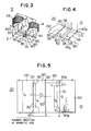
- FIG. 3 is an oblique view of a magnetic head according to the present invention.
- Fig. 4 is an oblique view of the principal part of that magnetic head.
- Fig. 5 is a front view of the principal part of that magnetic head.
- a read/write head chip 20 of the magnetic head 5 according to the present invention is composed of a plate-like magnetic substance 60 with grooves 80 and 80 formed on both sides thereof, an unmagnetic substance layer 35 for forming a gap 30, and a magnetic substance 100.
- the erase head chip 10 is composed of a plate-like magnetic substance 65 with a groove 70 on the central part thereof, an unmagnetic substance layer 45 for forming gaps 40a and 40b, and a magnetic substance 90. Between the head chip 10 and the head chip 20, a plate 50 composed of an unmagnetic substance is placed. In the same way as the unmagnetic substance layers 35 and 45, magnetic substances are injected into the grooves 70 and 80 as well. And the magnetic head is formed as follows, for example.
- magnetic substances 60 and 65 are bound by using glass as a binding agent to form a layer substance or laminated substance. Both sides of one of magnetic substances 60 in this layer substance are ground or machined to form grooves 80 and 80. The central part of the other of magnetic substances 65 is ground to form a groove 70. Then, on both faces of the layer substance, a S 1 0 2 film having a thickness of approximately 0.6 ⁇ m is formed by sputtering. A magnetic substance 100 is bound to the magnetic substance 60 through unmagnetic films 35 and 45. A magnetic substance 90 is bound to the magnetic substance 65.
- a gap 30 as well as gaps 40a and 40b are formed from the S i 0 2 films 35 and 45.
- glass 46 and 36 is injected into the grooves 70 and 80.
- the erase gap 40a overlaps with the read/write gap 30 in a distance ⁇ l.
- the width 1 4 of the gap 30 is larger than the distance l 5 between the gap 40a and the gap 40b.
- the gap 40a and the gap 30a are produced by appropriately selecting positions and sizes of the grooves 70 and 80.
- the distance l 5 between the gap 40a and the gap 40b is defined to be approximately the same value as the width of the magnetic track whereon a signal is recorded. When the density of the magnetic track has been defined to be 100 tracks/inch, the distance l 5 is chosen to be approximately 150 ⁇ m.
- widths l 1 and l 2 of erase gaps 40a and 40b are determined by the positioning error of the magnetic head, the amount of expansion and contraction of the magnetic disk caused by, for example, variation of the ambient temperature and humidity, and the size error of the magnetic head itself. Usually, it is suitable to select nearly identical values for the widths l 1 and l 2 of the gaps 40a and 40b. When the above described error or the amount of expansion and contraction is large, the width 1 1 and the width 1 2 must be larger. If the width l 1 is approximately the same as the width l 2 , the widths of two guard heads become nearly identical.
- the overlap width ⁇ l of the gap 30 and the gap 40a must be defined in the following way.
- a plurality of magnetic tracks on the magnetic disk are formed in the ring shape and concentrically. Therefore, it is a matter of course that the radius of the magnetic track recorded on the most external circumference is different from that of the magnetic track recorded on the most internal circumference.
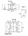
- Fig. 6 exaggeratingly. illustrates the most external magnetic track and the most internal magnetic track.
- the most external magnetic track 4A represented by the solid line passes through the erase gap 40a at a position which is different from that for the most internal magnetic track 4B represented by the broken line.
- the overlap width illustrated in Fig. 5 and Fig. 6 must be larger than the difference between those positions.
- the radius of the most external track, the radius of the most internal track, and the distance between the gap 30 and gap 40a or 40b are respectively R max , R min and i
- the overlap width ⁇ l. is so chosen as to satisfy the following expression:
- the overlap width ⁇ l is represented as
- the width ⁇ l is chosen so as to satisfy the expression (1), there hardly remain unerased tracks. If the width ⁇ l is chosen so as to satisfy the expression (2), there remains a slight unerased portion in a magnetic track which is situated near to the most internal magnetic track. However, the unerased portion can be suppressed so as not to pose a practical problem.
- the width l 4 of the gap 30 is naturally chosen with respect to the distance between the gap 40a and the gap 40b so as to satisfy the relation l 4 >l 5 .
- the distance between the center P of the gap 30 and the middle point Q of the gaps 40a and 40b is L. And the distance L is represented as
- Fig. 8 shows the second embodiment of a magnetic head according to the present invention.
- the width 1 4 of the gap 30 will be approximately equal to the distance l 5 between the gap 40a and the gap 40b.
- the width ⁇ l satisfies the equation (1) or (2).
- the width ⁇ l' is derived from the following expression (3) in the same way as Fig. 7:
- the distance L is represented as:
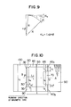
- the width ⁇ l and the width ⁇ l' have been defined assuming that the magnetic head is mounted at a proper position. In general, however, the magnetic head is not placed at a right position. The magnetic head is usually fixed with an azimuth angle ⁇ . Therefore, the error caused by this azimuth angle ⁇ must be included in the widths ⁇ and ⁇ l'. As shown in Fig. 9, the error ⁇ la caused by the aximuth angle is represented as should an azimuth angle occur in the second emboidment, a part of data is apt to remain unerased.
- the widths ⁇ l and ⁇ l' have been derived assuming that the head chips 10 and 20 are produced with correct precision. However, it is a matter of course that errors exist in sizes of the head chips 10 and 20. Therefore, errors of sizes must also be noted.
- the third embodiment of a magnetic head according to the present invention will now be described referring to Fig. 10.
- size errors and the error due to the azimuth angle ⁇ are taken into consideration.
- the width ⁇ l of the overlap portion 38 which has been formed in a part of the gap 30 is represented as
- the width ⁇ l includes the tolerance for errors brought about in sizes.
- an overlap portion 39 having the width of ⁇ l" is formed.
- the width ⁇ l" is brought about a tolerance for the width ⁇ l' illustrated in Fig. 8 added to the tolerance for the error due to the azimuth angle Ae and errors in sizes.
- the distance L is chosen as
- Fig. 11 shows the fourth embodiment of a magnetic head according to the present invention.
- grooves 80 and 80 are formed on the magnetic substance 100 and the groove 70 is formed on the magnetic substance 90.
- the head chip 10 and the head chip 20 are separately produced. Thereafter, the head chip 10 and the head chip 20 are bound together with the unmagnetic substance 50 made of ceramics in between to be formed as one body. Excepting the construction of grooves 70 and 80, the magnetic head in the fourth embodiment is formed in the same way as the third embodiment.
- Fig. 12 shows the fifth embodiment of a magnetic head according to the present invention.
- grooves 75 and 75 are formed at ends of gaps 40a and 40b on the magnetic substances 65 and 90.
- the widths of the gap 30 as well as gaps 40a and 40b are not large. Instead, the width t3 of magnetic substances 60, 65, 90 and 100 is made large. As a result, the strength of the head chips 10 and 20 is increased.
- an unmagnetic substance is injected in the same way as the groove 70.
- each drawing shows the top view of the magnetic head.
- each drawing will represent the bottom view.
- the read/write gap placed in parallel to and at a distance Q from a pair of erase gaps is deviated from that pair of erase gaps by a distance L.
Landscapes
- Engineering & Computer Science (AREA)
- Manufacturing & Machinery (AREA)
- Adjustment Of The Magnetic Head Position Track Following On Tapes (AREA)
- Digital Magnetic Recording (AREA)
Applications Claiming Priority (2)
| Application Number | Priority Date | Filing Date | Title |
|---|---|---|---|
| JP57097635A JPS58215717A (ja) | 1982-06-09 | 1982-06-09 | 磁気ヘツド |
| JP97635/82 | 1982-06-09 |
Publications (2)
| Publication Number | Publication Date |
|---|---|
| EP0096418A2 true EP0096418A2 (de) | 1983-12-21 |
| EP0096418A3 EP0096418A3 (de) | 1984-11-14 |
Family
ID=14197604
Family Applications (1)
| Application Number | Title | Priority Date | Filing Date |
|---|---|---|---|
| EP83105628A Withdrawn EP0096418A3 (de) | 1982-06-09 | 1983-06-08 | Magnetkopf für Magnetplatte |
Country Status (6)
| Country | Link |
|---|---|
| US (1) | US4613920A (de) |
| EP (1) | EP0096418A3 (de) |
| JP (1) | JPS58215717A (de) |
| KR (1) | KR840005248A (de) |
| AU (1) | AU1547083A (de) |
| CA (1) | CA1218147A (de) |
Cited By (2)
| Publication number | Priority date | Publication date | Assignee | Title |
|---|---|---|---|---|
| EP0118188A1 (de) * | 1983-02-08 | 1984-09-12 | Sony Corporation | Magnetisches Plattenaufnahme- und Wiedergabegerät |
| EP0479703A1 (de) * | 1990-10-02 | 1992-04-08 | International Business Machines Corporation | Verfahren und Vorrichtung zum Positionieren von Wandlern |
Families Citing this family (9)
| Publication number | Priority date | Publication date | Assignee | Title |
|---|---|---|---|---|
| JPS5945625A (ja) * | 1982-09-06 | 1984-03-14 | Nippon Telegr & Teleph Corp <Ntt> | 磁気ヘツド |
| JPS6061910A (ja) * | 1983-09-16 | 1985-04-09 | Mitsubishi Electric Corp | 磁気ヘツド組立体 |
| DE3524424A1 (de) * | 1984-07-10 | 1986-01-16 | Hitachi Maxell, Ltd., Ibaraki, Osaka | Magnetkopf |
| JPS6310309A (ja) * | 1986-07-01 | 1988-01-16 | Nec Corp | 磁気ヘツド |
| JPH01182917A (ja) * | 1988-01-13 | 1989-07-20 | Teac Corp | 磁気ヘッド |
| US6005751A (en) * | 1994-01-28 | 1999-12-21 | Seagate Technology, Inc. | Recording head skewed read gap/write gap positioning |
| JP2587603B2 (ja) * | 1995-03-22 | 1997-03-05 | 群馬日本電気株式会社 | フレキシブルディスク装置の記録再生制御回路 |
| US5940250A (en) * | 1997-10-21 | 1999-08-17 | Maxtor Corporation | Disk drive head having a read wide/write narrow architecture |
| US6359749B1 (en) * | 1999-10-15 | 2002-03-19 | International Business Machines Corporation | Dual element head with radial offset optimized for minimal write-to-read track error |
Family Cites Families (8)
| Publication number | Priority date | Publication date | Assignee | Title |
|---|---|---|---|---|
| US3557445A (en) * | 1968-01-02 | 1971-01-26 | Honeywell Inc | Method of fabricating slant cores |
| US3684841A (en) * | 1969-12-30 | 1972-08-15 | Honeywell Inc | Multi-channel magnetic transducer structure having full width erase head in non-magnetic housing |
| US3668332A (en) * | 1970-08-26 | 1972-06-06 | Xerox Corp | Magnetic recording heat which accurately defines the width of the recording track |
| JPS531646B2 (de) * | 1973-10-02 | 1978-01-20 | ||
| JPS5358218A (en) * | 1976-11-08 | 1978-05-26 | Toshiba Corp | Magnetic head |
| JPS56156920A (en) * | 1980-04-30 | 1981-12-03 | Toshiba Corp | Composite magnetic head and its production |
| US4367505A (en) * | 1980-09-29 | 1983-01-04 | Xerox Corporation | Magnetic head assembly with skewed read/write gap |
| JPS57186222A (en) * | 1981-05-13 | 1982-11-16 | Y Ii Data:Kk | Magnetic head |
-
1982
- 1982-06-09 JP JP57097635A patent/JPS58215717A/ja active Pending
-
1983
- 1983-06-07 KR KR1019830002514A patent/KR840005248A/ko not_active Withdrawn
- 1983-06-07 CA CA000429866A patent/CA1218147A/en not_active Expired
- 1983-06-08 EP EP83105628A patent/EP0096418A3/de not_active Withdrawn
- 1983-06-08 AU AU15470/83A patent/AU1547083A/en not_active Abandoned
- 1983-06-08 US US06/502,269 patent/US4613920A/en not_active Expired - Fee Related
Cited By (2)
| Publication number | Priority date | Publication date | Assignee | Title |
|---|---|---|---|---|
| EP0118188A1 (de) * | 1983-02-08 | 1984-09-12 | Sony Corporation | Magnetisches Plattenaufnahme- und Wiedergabegerät |
| EP0479703A1 (de) * | 1990-10-02 | 1992-04-08 | International Business Machines Corporation | Verfahren und Vorrichtung zum Positionieren von Wandlern |
Also Published As
| Publication number | Publication date |
|---|---|
| JPS58215717A (ja) | 1983-12-15 |
| EP0096418A3 (de) | 1984-11-14 |
| AU1547083A (en) | 1983-12-15 |
| CA1218147A (en) | 1987-02-17 |
| KR840005248A (ko) | 1984-11-05 |
| US4613920A (en) | 1986-09-23 |
Similar Documents
| Publication | Publication Date | Title |
|---|---|---|
| US5132861A (en) | Systems using superimposed, orthogonal buried servo signals | |
| US5321570A (en) | Systems using superimposed, orthogonal buried servo signals | |
| EP0517531B1 (de) | Mehrfachspur-Servoaufnahmevorrichtung | |
| JPS624769B2 (de) | ||
| WO1989009466A1 (en) | Bimodal multi-track magnetic head | |
| US20040060163A1 (en) | Method of making a monolithic maganetic read-while-write head apparatus | |
| EP0096418A2 (de) | Magnetkopf für Magnetplatte | |
| US7106555B2 (en) | Magnetic head, magnetic tape device including the magnetic head and method for producing the magnetic head | |
| US4479156A (en) | Magnetic disk recorder | |
| US5223994A (en) | System using superimposed, orthogonal buried servo signals | |
| US5130875A (en) | Multichannel magnetic head having a plurality of head chips fixed on a common head base | |
| GB2098378A (en) | Magnetic head | |
| JPS61276110A (ja) | 磁気抵抗効果型磁気ヘツド | |
| US4675758A (en) | Magnetic disc recording and/or reproducing apparatus | |
| EP0052392B1 (de) | Magnetkopf für hohe Spurdichte | |
| EP0086015B1 (de) | Magnetkopf mit stufenförmiger Spalte | |
| EP0263681B1 (de) | Magnetwandlerkopf-Struktur | |
| US5072323A (en) | Magnetic head without an erasure gap for recording new signals over old data | |
| US6894868B2 (en) | Magnetic head | |
| JPS634244B2 (de) | ||
| JPS5945625A (ja) | 磁気ヘツド | |
| KR870000043B1 (ko) | 상호 방위각손실방식 다중 트랙복합 헤드 | |
| JPS62157313A (ja) | 往復記録再生ヘツド | |
| JP2922671B2 (ja) | 磁気ヘッド装置 | |
| JPH0281308A (ja) | 磁気ヘッド |
Legal Events
| Date | Code | Title | Description |
|---|---|---|---|
| PUAI | Public reference made under article 153(3) epc to a published international application that has entered the european phase |
Free format text: ORIGINAL CODE: 0009012 |
|
| AK | Designated contracting states |
Designated state(s): DE GB |
|
| PUAL | Search report despatched |
Free format text: ORIGINAL CODE: 0009013 |
|
| AK | Designated contracting states |
Designated state(s): DE GB |
|
| 17P | Request for examination filed |
Effective date: 19850321 |
|
| 17Q | First examination report despatched |
Effective date: 19860912 |
|
| STAA | Information on the status of an ep patent application or granted ep patent |
Free format text: STATUS: THE APPLICATION HAS BEEN WITHDRAWN |
|
| 18W | Application withdrawn |
Withdrawal date: 19870120 |
|
| RIN1 | Information on inventor provided before grant (corrected) |
Inventor name: KONNO, KAZUTOSHI Inventor name: SAMPEI, TOHRU Inventor name: HIGUCHI, SHIGEMITSU |