EP0094680A1 - Unité de poupée avec moteur incorporé - Google Patents
Unité de poupée avec moteur incorporé Download PDFInfo
- Publication number
- EP0094680A1 EP0094680A1 EP83104864A EP83104864A EP0094680A1 EP 0094680 A1 EP0094680 A1 EP 0094680A1 EP 83104864 A EP83104864 A EP 83104864A EP 83104864 A EP83104864 A EP 83104864A EP 0094680 A1 EP0094680 A1 EP 0094680A1
- Authority
- EP
- European Patent Office
- Prior art keywords
- spindle
- fluid
- head unit
- motor
- incorporated
- Prior art date
- Legal status (The legal status is an assumption and is not a legal conclusion. Google has not performed a legal analysis and makes no representation as to the accuracy of the status listed.)
- Granted
Links
Images
Classifications
-
- B—PERFORMING OPERATIONS; TRANSPORTING
- B23—MACHINE TOOLS; METAL-WORKING NOT OTHERWISE PROVIDED FOR
- B23Q—DETAILS, COMPONENTS, OR ACCESSORIES FOR MACHINE TOOLS, e.g. ARRANGEMENTS FOR COPYING OR CONTROLLING; MACHINE TOOLS IN GENERAL CHARACTERISED BY THE CONSTRUCTION OF PARTICULAR DETAILS OR COMPONENTS; COMBINATIONS OR ASSOCIATIONS OF METAL-WORKING MACHINES, NOT DIRECTED TO A PARTICULAR RESULT
- B23Q11/00—Accessories fitted to machine tools for keeping tools or parts of the machine in good working condition or for cooling work; Safety devices specially combined with or arranged in, or specially adapted for use in connection with, machine tools
- B23Q11/12—Arrangements for cooling or lubricating parts of the machine
- B23Q11/126—Arrangements for cooling or lubricating parts of the machine for cooling only
- B23Q11/127—Arrangements for cooling or lubricating parts of the machine for cooling only for cooling motors or spindles
-
- B—PERFORMING OPERATIONS; TRANSPORTING
- B23—MACHINE TOOLS; METAL-WORKING NOT OTHERWISE PROVIDED FOR
- B23Q—DETAILS, COMPONENTS, OR ACCESSORIES FOR MACHINE TOOLS, e.g. ARRANGEMENTS FOR COPYING OR CONTROLLING; MACHINE TOOLS IN GENERAL CHARACTERISED BY THE CONSTRUCTION OF PARTICULAR DETAILS OR COMPONENTS; COMBINATIONS OR ASSOCIATIONS OF METAL-WORKING MACHINES, NOT DIRECTED TO A PARTICULAR RESULT
- B23Q5/00—Driving or feeding mechanisms; Control arrangements therefor
- B23Q5/02—Driving main working members
- B23Q5/04—Driving main working members rotary shafts, e.g. working-spindles
- B23Q5/10—Driving main working members rotary shafts, e.g. working-spindles driven essentially by electrical means
-
- H—ELECTRICITY
- H02—GENERATION; CONVERSION OR DISTRIBUTION OF ELECTRIC POWER
- H02K—DYNAMO-ELECTRIC MACHINES
- H02K9/00—Arrangements for cooling or ventilating
-
- H—ELECTRICITY
- H02—GENERATION; CONVERSION OR DISTRIBUTION OF ELECTRIC POWER
- H02K—DYNAMO-ELECTRIC MACHINES
- H02K9/00—Arrangements for cooling or ventilating
- H02K9/02—Arrangements for cooling or ventilating by ambient air flowing through the machine
- H02K9/04—Arrangements for cooling or ventilating by ambient air flowing through the machine having means for generating a flow of cooling medium
-
- Y—GENERAL TAGGING OF NEW TECHNOLOGICAL DEVELOPMENTS; GENERAL TAGGING OF CROSS-SECTIONAL TECHNOLOGIES SPANNING OVER SEVERAL SECTIONS OF THE IPC; TECHNICAL SUBJECTS COVERED BY FORMER USPC CROSS-REFERENCE ART COLLECTIONS [XRACs] AND DIGESTS
- Y10—TECHNICAL SUBJECTS COVERED BY FORMER USPC
- Y10T—TECHNICAL SUBJECTS COVERED BY FORMER US CLASSIFICATION
- Y10T408/00—Cutting by use of rotating axially moving tool
- Y10T408/94—Tool-support
- Y10T408/95—Tool-support with tool-retaining means
-
- Y—GENERAL TAGGING OF NEW TECHNOLOGICAL DEVELOPMENTS; GENERAL TAGGING OF CROSS-SECTIONAL TECHNOLOGIES SPANNING OVER SEVERAL SECTIONS OF THE IPC; TECHNICAL SUBJECTS COVERED BY FORMER USPC CROSS-REFERENCE ART COLLECTIONS [XRACs] AND DIGESTS
- Y10—TECHNICAL SUBJECTS COVERED BY FORMER USPC
- Y10T—TECHNICAL SUBJECTS COVERED BY FORMER US CLASSIFICATION
- Y10T409/00—Gear cutting, milling, or planing
- Y10T409/30—Milling
- Y10T409/303976—Milling with means to control temperature or lubricate
-
- Y—GENERAL TAGGING OF NEW TECHNOLOGICAL DEVELOPMENTS; GENERAL TAGGING OF CROSS-SECTIONAL TECHNOLOGIES SPANNING OVER SEVERAL SECTIONS OF THE IPC; TECHNICAL SUBJECTS COVERED BY FORMER USPC CROSS-REFERENCE ART COLLECTIONS [XRACs] AND DIGESTS
- Y10—TECHNICAL SUBJECTS COVERED BY FORMER USPC
- Y10T—TECHNICAL SUBJECTS COVERED BY FORMER US CLASSIFICATION
- Y10T409/00—Gear cutting, milling, or planing
- Y10T409/30—Milling
- Y10T409/309352—Cutter spindle or spindle support
- Y10T409/309408—Cutter spindle or spindle support with cutter holder
-
- Y—GENERAL TAGGING OF NEW TECHNOLOGICAL DEVELOPMENTS; GENERAL TAGGING OF CROSS-SECTIONAL TECHNOLOGIES SPANNING OVER SEVERAL SECTIONS OF THE IPC; TECHNICAL SUBJECTS COVERED BY FORMER USPC CROSS-REFERENCE ART COLLECTIONS [XRACs] AND DIGESTS
- Y10—TECHNICAL SUBJECTS COVERED BY FORMER USPC
- Y10T—TECHNICAL SUBJECTS COVERED BY FORMER US CLASSIFICATION
- Y10T82/00—Turning
- Y10T82/25—Lathe
- Y10T82/2552—Headstock
- Y10T82/2561—Spindle or work angler
Definitions
- the present invention relates to a spindle head unit incorporating a spindle drive motor assembly, more particularly, to such a spindle head unit provided with a built-in heat insulation system between the spindle drive motor and the the spindle as well as the spindle support bearings.
- An object of the present invention is therefore to provide a motor-incorporated spindle head unit with a heat insulating system effective for interrupting the heat transfer from the spindle drive motor to the spindle as well as the spindle support bearings.
- Another object of the present invention is to provide a motor-incorporated spindle head unit having an internal structure capable of simultaneously achieving cooling of the spindle motor and interruption of heat transfer from the spindle motor to the front part of the spindle head unit.
- a motor-incorporated spindle head unit accommodating a heat insulating system arranged between a spindle support bearing unit adjacent to the spindle nose and the spindle drive motor.
- the heat insulating system comprises a fluid passage unit including a fluid inlet for introducing a fluid into the fluid passage unit, a fluid outlet arranged remotely from the fluid inlet for discharging the fluid to the atmosphere, and an annular passage for permitting the fluid to flow from the inlet toward the outlet around a part of the spindle adjacent to the spindle nose.
- the fluid is preferably air.
- the motor-incorporated spindle head unit comprises a cooling unit for cooling the stator assembly of the spindle motor by the use of cooling air.
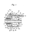
- a spindle head unit 10 includes a centrally disposed spindle 12 having axially front and rear end parts 14 and 15.
- the front end part 14 of the spindle 12 is formed as a spindle nose having a tapered bore in which a tool holder or a workpiece holder is received as required.
- the spindle 12 is rotatably supported by bearings 16 and 18 arranged at the front and rear end parts 14 and 15, respectively.
- the front end part 14 is particularly supported by a plurality of bearings 16 so that it may stably hold the tool holder or the workpiece holder during the rotation of the spindle 12.
- Both the front bearings 16 and the rear bearings 18 are received in a housing 20.
- the front bearings 16 are mounted in the housing 20 through a flanged bush 22 and are restrained from axial movement by a suitable retaining member 24, a collar 26, and a nut 28 threadedly engaged with the spindle 12.
- the rear end part 15 of the spindle 12 is provided for mounting thereon a conventional rotation detector, such as a rotary encoder for detecting the rotary speed of the spindle 12.
- the housing 20 has a mounting space and may be used for attaching the spindle head unit 10 on the body of a machine tool.
- a rotor assembly 32 of a drive motor 30, i.e., an AC drive motor, is fixed to a substantially middle part of the spindle 12. That is, the rotor assembly 32 is rotatable with the spindle 12.
- a stator assembly 34 of the drive motor 30 is stationarily and coaxially arranged around the rotor assembly 32 with a small air gap remaining between both assemblies.
- the stator assembly 34 is secured to the housing 20 by a suitable fixing means, such as adhesives and screws.
- the drive motor 30 is incorporated in the mounting space of the housing 20 of the spindle head unit 10.
- the rotary drive force of the rotor assembly 32 for rotating the spindle 12 generates when excitation windings 34a of the stator assembly 34 is supplied with electric current.
- the supply of electric current to the excitation windings 34a of the stator assembly 34 generates heat in the stator assembly 34 due to the iron and copper losses. Therefore, a cooling system 36 is interposed between the outer circumference of the stator assembly 34 and the housing 20 so as to cool the heated stator assembly 34.
- the cooling system 36 is constituted so as to introduce external air from the rear end of the housing 20 into a cooling air passage 38 formed inside of the housing 20.
- the cooling air is first brought near to the front end part 14 of the spindle 12 through the cooling air passage 38 and then back to the rear end of the housing 20 through a return passage 40 formed within the stator core of the stator assembly 34. Subsequently, the cooling air, which has absorbed heat while passing through the cooling air passage 38 and the return passage 40, is discharged from a cooling air exhaust pipe 42.
- An exhaust fan 44 is arranged at the outer extremity of the cooling air exhaust pipe 42 so as to forcibly discharge the cooling air toward the atmosphere.
- the flow of the cooling air through the cooling system 36 is designated by arrows in Fig. 1. That is, the U-shaped cooling air circulation as shown in Fig. 1 contributes to the effective cooling of the stator assembly 34 of the spindle drive motor 30 due to the removal of heat by the flow of the cooling air.
- a heat insulating system 50 is arranged between the front bearings 16 and the spindle drive motor 30.
- the heat insulating system 50 has an annular heat insulating passage 56 consisting of an annular bore 52 formed inside of a front part of the housing 20 and a sealing partition plate 54 made of a suitable heat nonconductive material disposed in front of the spindle drive motor 30.
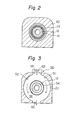
- the annular heat insulating passage 56 communicates with an air inlet 58 formed in the housing 20 and an air outlet 60 formed also in the housing 20.
- the air outlet 60 is located diametrically opposite to the air inlet 58.
- Air is introduced from the outside into the annular heat insulating passage 56 by an air supplying fan 62 disposed above the air inlet 58 and is discharged toward the outside through the air outlet 60.
- the thus formed heat insulator of flowing air between the front bearings 16 supporting the spindle 12 and the spindle drive motor 30 intercepts heat from the spindle drive motor 30 to the front bearings 16.
- the air that flows through the annular heat insulating passage 56 also serves to remove heat from the spindle head unit 10.
- the spindle head unit 10 is formed in a compact and integral assembly of the spindle 12, the bearing units, and the incorporated spindle drive motor 30, the provision of the heat insulating system 50 between the bearing units and the spindle drive motor 30 intercepts the heat generated from the spindle drive motor 30 to the spindle 12 and the front bearing unit. Accordingly, the temperature of the front bearing unit is maintained within a practically fixed range at all times during operation and hence inaccurate alignment and other undesirable operation of the spindle 12 due to thermal expansion or thermal deformation are prevented. Therefore, a highly accurate machining operation is ensured by the use of the motor--incorporated spindle head unit. Further, the transfer of heat from the spindle drive motor 30 to the front bearings 16 as well as the spindle 12 can be avoided even if the amount of heat increases in response to an increase in the output power of the incorporated spindle drive motor.
Landscapes
- Engineering & Computer Science (AREA)
- Power Engineering (AREA)
- Mechanical Engineering (AREA)
- Turning (AREA)
- Auxiliary Devices For Machine Tools (AREA)
- Motor Or Generator Cooling System (AREA)
Applications Claiming Priority (2)
| Application Number | Priority Date | Filing Date | Title |
|---|---|---|---|
| JP81584/82 | 1982-05-17 | ||
| JP57081584A JPS58201559A (ja) | 1982-05-17 | 1982-05-17 | 主軸台の断熱装置 |
Publications (2)
| Publication Number | Publication Date |
|---|---|
| EP0094680A1 true EP0094680A1 (fr) | 1983-11-23 |
| EP0094680B1 EP0094680B1 (fr) | 1986-10-15 |
Family
ID=13750367
Family Applications (1)
| Application Number | Title | Priority Date | Filing Date |
|---|---|---|---|
| EP83104864A Expired EP0094680B1 (fr) | 1982-05-17 | 1983-05-17 | Unité de poupée avec moteur incorporé |
Country Status (4)
| Country | Link |
|---|---|
| US (1) | US4580471A (fr) |
| EP (1) | EP0094680B1 (fr) |
| JP (1) | JPS58201559A (fr) |
| DE (1) | DE3366864D1 (fr) |
Cited By (5)
| Publication number | Priority date | Publication date | Assignee | Title |
|---|---|---|---|---|
| EP0376178A1 (fr) * | 1988-12-30 | 1990-07-04 | INDEX-WERKE GMBH & CO. KG HAHN & TESSKY | Machine-outils à moteur de broche refroidi |
| EP0381009A2 (fr) * | 1989-01-28 | 1990-08-08 | Gildemeister AG | Motorisation de la broche d'une machine-outil |
| DE4311431A1 (de) * | 1993-04-07 | 1994-10-13 | Index Werke Kg Hahn & Tessky | Motorspindel für eine Werkzeugmaschine |
| DE19849573A1 (de) * | 1998-10-27 | 2000-05-11 | Siemens Ag | Elektromotor mit Kühlung |
| EP1880798A1 (fr) * | 2006-07-18 | 2008-01-23 | Franz Kessler GmbH | Unité de broche destinée au montage dans une machine-outil |
Families Citing this family (29)
| Publication number | Priority date | Publication date | Assignee | Title |
|---|---|---|---|---|
| US4720897A (en) * | 1985-08-30 | 1988-01-26 | Gemcor Engineering Corp. | Automatic fastening machine with brushless electric motor for drill spindle drive |
| DE8703410U1 (fr) * | 1987-03-06 | 1987-05-21 | J.M. Voith Gmbh, 7920 Heidenheim, De | |
| JP2590334B2 (ja) * | 1987-05-08 | 1997-03-12 | 長野日本電産 株式会社 | カップ形ロ−タを有する磁気ディスク駆動用モ−タ |
| US4829861A (en) * | 1987-11-10 | 1989-05-16 | Hardinge Brothers, Inc. | Headstock assembly for a chucker and bar machine |
| US4867619A (en) * | 1988-10-07 | 1989-09-19 | Colonial Tool Operations Division Of Textron Canada Ltd. | High speed spindle with adjustable tool |
| DE3928985A1 (de) * | 1989-09-01 | 1991-03-14 | Index Werke Kg Hahn & Tessky | Werkstueckspindel-anordnung fuer eine drehmaschine |
| US5213019A (en) * | 1991-07-17 | 1993-05-25 | Hardinge Brothers, Inc. | Headstock cooling system for a machine tool |
| DE4214667C1 (en) * | 1992-05-02 | 1993-09-09 | Schleifmaschinenwerk Gmbh Chemnitz, O-9034 Chemnitz, De | Cooling unit facility for electric motor drive of machine tool - includes cooling flange with heat insulating flange fitted between machine tool housing, and centring set of motor housing flange secured by fixing elements |
| DE4220310C2 (de) * | 1992-06-22 | 1995-09-21 | San Rocco Donzelli Ind S P A | Arbeitsspindel mit Luftkühlung |
| WO1995021723A1 (fr) * | 1994-02-15 | 1995-08-17 | Seiko Seiki Kabushiki Kaisha | Machine-outil a deux broches reversibles |
| JP3687693B2 (ja) * | 1995-11-21 | 2005-08-24 | 株式会社安川電機 | 電動モータ |
| US6089797A (en) * | 1998-11-30 | 2000-07-18 | Excellon Automation, Co. | Thermal equalization system |
| SE9901052L (sv) * | 1999-03-23 | 2000-02-28 | Lind Finance & Dev Ab | Anordning vid verktygsspindel |
| SE9901053L (sv) * | 1999-03-23 | 2000-02-28 | Lind Finance & Dev Ab | Anordning vid verktygsspindel |
| US6734584B1 (en) | 2001-06-11 | 2004-05-11 | Reliance Electric Technologies, Llc | Thermal barrier and cooling air deflector for totally enclosed motor |
| KR20030069663A (ko) * | 2002-02-22 | 2003-08-27 | 주식회사 광진기계 | 팬을 구비한 스핀들 모터구조 |
| DE10310677A1 (de) * | 2003-03-12 | 2004-10-07 | Atlas Copco Energas Gmbh | Turbomaschine |
| US7185573B1 (en) * | 2005-02-18 | 2007-03-06 | Hayes Lemmerz International, Inc. | Vacuum wheel chuck |
| JP5009588B2 (ja) * | 2006-10-26 | 2012-08-22 | 株式会社ツガミ | 主軸装置 |
| DE102006061236A1 (de) * | 2006-12-22 | 2008-06-26 | Robert Bosch Gmbh | Oberfräse |
| CN102699354B (zh) * | 2012-05-21 | 2013-12-11 | 慈溪市贝利轴承有限公司 | 一种节能型电主轴 |
| US9488506B2 (en) * | 2012-09-26 | 2016-11-08 | Minebea Co., Ltd. | Resolver |
| CN106077719A (zh) * | 2016-08-30 | 2016-11-09 | 伊泽瑞尔(大连)科技有限公司 | 一种永磁同步电主轴 |
| JP6378290B2 (ja) * | 2016-11-11 | 2018-08-22 | ファナック株式会社 | 工作機械 |
| JP6948915B2 (ja) * | 2017-10-31 | 2021-10-13 | シチズン時計株式会社 | 工作機械 |
| JP6737846B2 (ja) * | 2018-07-31 | 2020-08-12 | ファナック株式会社 | 主軸装置 |
| CN109940452B (zh) * | 2019-04-18 | 2020-08-04 | 上海理工大学 | 电主轴热电冷却装置 |
| CN110732689A (zh) * | 2019-11-27 | 2020-01-31 | 江苏思维福特机械科技股份有限公司 | 一种加工中心用高精度运转电主轴 |
| DE102023002494A1 (de) | 2022-07-04 | 2024-01-04 | Sew-Eurodrive Gmbh & Co Kg | Elektromotor mit Lüfter |
Citations (4)
| Publication number | Priority date | Publication date | Assignee | Title |
|---|---|---|---|---|
| US2039146A (en) * | 1932-05-12 | 1936-04-28 | Warner Swasey Co | Machine tool |
| US3840762A (en) * | 1972-03-22 | 1974-10-08 | Rockwell International Corp | Vacuum-cooled power tool |
| DE2724440A1 (de) * | 1976-06-01 | 1978-01-05 | Fujitsu Fanuc Ltd | Werkzeugmaschine |
| US4167218A (en) * | 1977-02-28 | 1979-09-11 | Kabushiki Kaisha Meidensha | Machine tool arrangement |
Family Cites Families (7)
| Publication number | Priority date | Publication date | Assignee | Title |
|---|---|---|---|---|
| US806048A (en) * | 1905-01-26 | 1905-11-28 | Ralph Baggaley | Heat-travel controller for furnace-walls. |
| US2343875A (en) * | 1941-08-09 | 1944-03-14 | Bell Aircraft Corp | Machine tool |
| US2725775A (en) * | 1951-12-20 | 1955-12-06 | Gisholt Machine Co | High-speed motor-driven lathe and temperature control means |
| FR1223607A (fr) * | 1959-01-31 | 1960-06-17 | Dispositif destiné à empêcher des dilatations locales dans des organes de machines dans lesquels tournent des broches porte-outils de grande capacité | |
| US3701911A (en) * | 1971-05-20 | 1972-10-31 | Skf Ind Trading & Dev | Motor bearing support and cooling means |
| US3862443A (en) * | 1973-11-15 | 1975-01-21 | Reliance Electric Co | Cooling means for bearing structure in dynamoelectric machine |
| FR2500776A1 (fr) * | 1981-03-02 | 1982-09-03 | Tech Mecanique Indles | Electro-broche d'usinage |
-
1982
- 1982-05-17 JP JP57081584A patent/JPS58201559A/ja active Pending
-
1983
- 1983-05-13 US US06/494,328 patent/US4580471A/en not_active Expired - Fee Related
- 1983-05-17 DE DE8383104864T patent/DE3366864D1/de not_active Expired
- 1983-05-17 EP EP83104864A patent/EP0094680B1/fr not_active Expired
Patent Citations (4)
| Publication number | Priority date | Publication date | Assignee | Title |
|---|---|---|---|---|
| US2039146A (en) * | 1932-05-12 | 1936-04-28 | Warner Swasey Co | Machine tool |
| US3840762A (en) * | 1972-03-22 | 1974-10-08 | Rockwell International Corp | Vacuum-cooled power tool |
| DE2724440A1 (de) * | 1976-06-01 | 1978-01-05 | Fujitsu Fanuc Ltd | Werkzeugmaschine |
| US4167218A (en) * | 1977-02-28 | 1979-09-11 | Kabushiki Kaisha Meidensha | Machine tool arrangement |
Cited By (9)
| Publication number | Priority date | Publication date | Assignee | Title |
|---|---|---|---|---|
| EP0376178A1 (fr) * | 1988-12-30 | 1990-07-04 | INDEX-WERKE GMBH & CO. KG HAHN & TESSKY | Machine-outils à moteur de broche refroidi |
| US5062330A (en) * | 1988-12-30 | 1991-11-05 | Index-Werke Komm.-Ges. Hahn & Tessky | Machine tool with a cooled motor spindle |
| EP0381009A2 (fr) * | 1989-01-28 | 1990-08-08 | Gildemeister AG | Motorisation de la broche d'une machine-outil |
| EP0381009A3 (en) * | 1989-01-28 | 1990-12-19 | Gildemeister Ag | Drive for the workpiece spindle of a machine-tool |
| US5088362A (en) * | 1989-01-28 | 1992-02-18 | Gildemeister Aktiengesellschaft | Drive for workpiece spindle of machine tool |
| DE4311431A1 (de) * | 1993-04-07 | 1994-10-13 | Index Werke Kg Hahn & Tessky | Motorspindel für eine Werkzeugmaschine |
| US5664916A (en) * | 1993-04-07 | 1997-09-09 | Index-Werke Gmbh & Co. Kg Hahn & Tessky | Cooling system for a motor spindle for a machine tool |
| DE19849573A1 (de) * | 1998-10-27 | 2000-05-11 | Siemens Ag | Elektromotor mit Kühlung |
| EP1880798A1 (fr) * | 2006-07-18 | 2008-01-23 | Franz Kessler GmbH | Unité de broche destinée au montage dans une machine-outil |
Also Published As
| Publication number | Publication date |
|---|---|
| US4580471A (en) | 1986-04-08 |
| JPS58201559A (ja) | 1983-11-24 |
| EP0094680B1 (fr) | 1986-10-15 |
| DE3366864D1 (en) | 1986-11-20 |
Similar Documents
| Publication | Publication Date | Title |
|---|---|---|
| US4580471A (en) | Motor-incorporated spindle head unit | |
| US4534686A (en) | Spindle head unit | |
| JP2899334B2 (ja) | 冷却型モータスピンドルをもった工作機械 | |
| GB1578268A (en) | Machine tool | |
| US3735174A (en) | Electric motor with hollow rotor and method of fabricating the hollow rotor | |
| CN110369736B (zh) | 一种高速气浮电主轴 | |
| US5751079A (en) | Alternator with internal and external fans | |
| CN114273685B (zh) | 一种气浮轴承及气浮轴承支承的高压气浮电主轴 | |
| EP3856451B1 (fr) | Tete multibroche | |
| CN110977060A (zh) | 磁悬浮内螺纹铜管加工设备 | |
| JP2661805B2 (ja) | 液冷用管路を外被内部に有した液冷モータ | |
| JPH02101944A (ja) | 回転軸の熱変位制御方法 | |
| JP4280383B2 (ja) | モータ内蔵主軸台における主軸冷却構造 | |
| JPH04343638A (ja) | 主軸用モータの冷却装置 | |
| CN217749366U (zh) | 一种加工中心机用高速高精度主轴机构 | |
| JP6881692B1 (ja) | 回転電機の冷却構造 | |
| EP0502216A1 (fr) | Dispositif refroidisseur pour element rotatif | |
| JPS58120439A (ja) | モ−タ内蔵主軸台 | |
| JP2586068B2 (ja) | 超電導回転電機の回転子及びその製造方法 | |
| JPH04364344A (ja) | 高速モータの冷却方法およびその装置 | |
| JP2003170327A (ja) | 工具、工具ホルダおよび工作機械 | |
| KR100544004B1 (ko) | 빌트인모터의냉각장치 | |
| JPH0720072U (ja) | スピンドルモータの冷却装置 | |
| JPH1148088A (ja) | 工作機械の主軸頭 | |
| JPH01147189A (ja) | クーラントポンプ |
Legal Events
| Date | Code | Title | Description |
|---|---|---|---|
| PUAI | Public reference made under article 153(3) epc to a published international application that has entered the european phase |
Free format text: ORIGINAL CODE: 0009012 |
|
| 17P | Request for examination filed |
Effective date: 19830517 |
|
| AK | Designated contracting states |
Designated state(s): DE FR GB |
|
| GRAA | (expected) grant |
Free format text: ORIGINAL CODE: 0009210 |
|
| AK | Designated contracting states |
Kind code of ref document: B1 Designated state(s): DE FR GB |
|
| REF | Corresponds to: |
Ref document number: 3366864 Country of ref document: DE Date of ref document: 19861120 |
|
| ET | Fr: translation filed | ||
| PLBE | No opposition filed within time limit |
Free format text: ORIGINAL CODE: 0009261 |
|
| STAA | Information on the status of an ep patent application or granted ep patent |
Free format text: STATUS: NO OPPOSITION FILED WITHIN TIME LIMIT |
|
| 26N | No opposition filed | ||
| PGFP | Annual fee paid to national office [announced via postgrant information from national office to epo] |
Ref country code: FR Payment date: 19910424 Year of fee payment: 9 |
|
| PGFP | Annual fee paid to national office [announced via postgrant information from national office to epo] |
Ref country code: GB Payment date: 19910507 Year of fee payment: 9 |
|
| PGFP | Annual fee paid to national office [announced via postgrant information from national office to epo] |
Ref country code: DE Payment date: 19910605 Year of fee payment: 9 |
|
| PG25 | Lapsed in a contracting state [announced via postgrant information from national office to epo] |
Ref country code: GB Effective date: 19920517 |
|
| GBPC | Gb: european patent ceased through non-payment of renewal fee |
Effective date: 19920517 |
|
| PG25 | Lapsed in a contracting state [announced via postgrant information from national office to epo] |
Ref country code: FR Effective date: 19930129 |
|
| PG25 | Lapsed in a contracting state [announced via postgrant information from national office to epo] |
Ref country code: DE Effective date: 19930202 |
|
| REG | Reference to a national code |
Ref country code: FR Ref legal event code: ST |