EP0094484A1 - Belüftungssystem mit Luftstromumlauf - Google Patents
Belüftungssystem mit Luftstromumlauf Download PDFInfo
- Publication number
- EP0094484A1 EP0094484A1 EP83102538A EP83102538A EP0094484A1 EP 0094484 A1 EP0094484 A1 EP 0094484A1 EP 83102538 A EP83102538 A EP 83102538A EP 83102538 A EP83102538 A EP 83102538A EP 0094484 A1 EP0094484 A1 EP 0094484A1
- Authority
- EP
- European Patent Office
- Prior art keywords
- hub
- disk
- disk drive
- filter
- enclosed
- Prior art date
- Legal status (The legal status is an assumption and is not a legal conclusion. Google has not performed a legal analysis and makes no representation as to the accuracy of the status listed.)
- Granted
Links
- 230000003134 recirculating effect Effects 0.000 title claims abstract description 21
- 125000006850 spacer group Chemical group 0.000 claims description 11
- 239000002245 particle Substances 0.000 description 7
- 238000005266 casting Methods 0.000 description 5
- 239000013618 particulate matter Substances 0.000 description 4
- 238000010926 purge Methods 0.000 description 4
- 230000008901 benefit Effects 0.000 description 2
- 238000007789 sealing Methods 0.000 description 2
- 230000000712 assembly Effects 0.000 description 1
- 238000000429 assembly Methods 0.000 description 1
- 239000000356 contaminant Substances 0.000 description 1
- 230000006735 deficit Effects 0.000 description 1
- 230000001939 inductive effect Effects 0.000 description 1
- 239000006249 magnetic particle Substances 0.000 description 1
- 238000004519 manufacturing process Methods 0.000 description 1
- 230000000717 retained effect Effects 0.000 description 1
- 238000010408 sweeping Methods 0.000 description 1
- -1 urethane compound Chemical class 0.000 description 1
- 238000004804 winding Methods 0.000 description 1
Images
Classifications
-
- G—PHYSICS
- G11—INFORMATION STORAGE
- G11B—INFORMATION STORAGE BASED ON RELATIVE MOVEMENT BETWEEN RECORD CARRIER AND TRANSDUCER
- G11B23/00—Record carriers not specific to the method of recording or reproducing; Accessories, e.g. containers, specially adapted for co-operation with the recording or reproducing apparatus ; Intermediate mediums; Apparatus or processes specially adapted for their manufacture
- G11B23/02—Containers; Storing means both adapted to cooperate with the recording or reproducing means
- G11B23/021—Containers; Storing means both adapted to cooperate with the recording or reproducing means comprising means for reducing influence of physical parameters, e.g. temperature change, moisture
-
- G—PHYSICS
- G11—INFORMATION STORAGE
- G11B—INFORMATION STORAGE BASED ON RELATIVE MOVEMENT BETWEEN RECORD CARRIER AND TRANSDUCER
- G11B17/00—Guiding record carriers not specifically of filamentary or web form, or of supports therefor
- G11B17/02—Details
- G11B17/038—Centering or locking of a plurality of discs in a single cartridge
-
- G—PHYSICS
- G11—INFORMATION STORAGE
- G11B—INFORMATION STORAGE BASED ON RELATIVE MOVEMENT BETWEEN RECORD CARRIER AND TRANSDUCER
- G11B23/00—Record carriers not specific to the method of recording or reproducing; Accessories, e.g. containers, specially adapted for co-operation with the recording or reproducing apparatus ; Intermediate mediums; Apparatus or processes specially adapted for their manufacture
- G11B23/50—Reconditioning of record carriers; Cleaning of record carriers ; Carrying-off electrostatic charges
- G11B23/505—Reconditioning of record carriers; Cleaning of record carriers ; Carrying-off electrostatic charges of disk carriers
- G11B23/507—Reconditioning of record carriers; Cleaning of record carriers ; Carrying-off electrostatic charges of disk carriers combined with means for reducing influence of physical parameters, e.g. temperature change, moisture
Definitions
- This invention pertains to drives for data carrying disk assemblies and more particularly to a recirculating airflow system for such drives.
- a common problem in magnetic disk drives is the sweeping of particulate matter from the data transfer surfaces. Since the transducer or slider carrying the transducer flies on an air bearing with a thickness measured in millionths of an inch, a particle having a dimension of only one micron is several times the air bearing thickness. Particles may be generated during manufacture despite clean room conditions, may be carried by air drawn into the disk enclosure, may occur through leakage past seals. Drive components exposed within the enclosure constitute another source of particles, particularly the head and disk which contact during start and stop operations. Most disk drives are now enclosed with filtered air passed through a recirculating path to limit the amount of air introduced into the enclosure to that resulting from changing conditions of temperature and pressure which can be channeled through a breather filter to entrap airborne particles.
- the permanent magnets and associated magnetic circuits are coated with a urethane compound to captivate magnetic particles and prevent them from getting into the airflow path.
- a urethane compound to captivate magnetic particles and prevent them from getting into the airflow path.
- the possible introduction of such particles is a hazard not only to the aerodynamics of the slider carrying the transducer, but also may erase data from the surface of the disk media.
- an enclosed disk drive having an enclosure including a base and a cover in which a plurality of disk media are rotated and accessed by movable transducers mounted on a carriage that is positioned by an actuator mechanism characterized in that it comprises a hub upon which said plurality of disk media are mounted for unitary rotation therewith; generally radially extending vanes formed in said hub; hub cover means having an axial aperture; spacer means adjoining said disk media including radial openings adjacent said disk media surfaces; clamping means securing said disk media, hub cover means and spacer means to said hub to define generally radially extending passage means from an axial inlet opening to said radial openings in said spacer means, whereby a radial airflow is induced by hub rotation; air passage means extending from the periphery of said disk media to adjacent said hub cover means axial aperture, said actuator mechanism being mounted in said passage means; and a filter mounted in said passage means downstream from said actuator mechanism.
- a breather filter is also placed in the return path at the lowest pressure point in the air system.
- the breather filter's primary function is to allow pressure equalization between the disk enclosure and the external environment.
- the filter's placement at a low pressure point provides another benefit. If a disk enclosure seal leak should develop, the leak will be outward and makeup air will be clean since it will be supplied through the breather filter.
- Recirculating systems have the advantage of much longer filter life, as the recirculating air has been exposed to clean file components only. In such a system both the recirculating air filter and the breather filter should last for the life of the file.
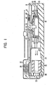
- FIG. 1 is a section view of a disk drive illustrating the present invention.
- the drive is housed in a base casting 10 and a closure cover 11 secured to the base casting.
- the disks 13, 14 are mounted for rotation in unison with hub 16.
- the disk mounting includes spacers 17, 18; clamping ring 19 and hub cap 20. With the disks compressively retained between the clamping ring 19 and hub flange projections 22 by a series of bolts 25.
- the generally cylindrical enclosed space in which the disks are maintained and the connected elongated space occupied by the transducer actuator are partially isolated from one another by a shroud or baffle 28.
- FIG. 1 is a section view of a disk drive illustrating the present invention.
- the drive is housed in a base casting 10 and a closure cover 11 secured to the base casting.
- the disks 13, 14 are mounted for rotation in unison with hub 16.
- the disk mounting includes spacers 17, 18; clamping ring 19 and hub cap 20. With the disks compressively
- FIG. 1 schematically shows only the outlines of the actuator mechanism 30 without the carriage and transducers that extend to a position of data transfer confronting relation with the surfaces of disks 13, 14.
- the air flows over the carriage (not shown) and through the actuator 30 to the return air circulation path provided by the filter-breather assembly 32.
- the assembly 32 has an inlet opening 33 that communicates with the actuator chamber defined by walls 34 (FIG.4). ,The full flow of the recirculating air passes through the recirculating filter 36 and the air exits from the assembly 32 through outlet opening 38 adjacent the axial opening 39 in hub cap 20.
- a breather filter separates particulate matter from the air that enters the system through opening 42. Air entering the system, as indicated by arrow A, may be caused by thermal expansion or other pressure changes or because of leakage that may occur at seals about covers or closure members.
- the breather filter 40 is located adjacent the axial inlet of the hub cap 20 which is at the inlet to the hub passageways that form the impeller for inducing the air recirculation.
- the breather filter location at the impeller inlet places the breather inlet at the lowest pressure portion of the air recirculation path. This placement will cause any impairment of the integrity of the seals to cause the air to be expelled since the air pressure at the locations of air leakage would be greater than at the inlet through the breather filter to assure that unfiltered air is not permitted to enter into the system.
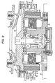
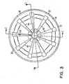
- FIG. 2 shows the hub structure in greater detail to demonstrate the function as a mounting for the disks, as an impeller for establishing the recirculating airflow and as a part of the drive motor rotor.
- the hub 16 (as seen also in FIG. 3) has a series of radial vanes 44 with intermediate recesses that provide the impeller action when enclosed by hub cap 20.
- the radially extending flange 45 terminates with a series of axially extending projections 22 which are aligned with the vanes 44 to provide the abutting support surfaces for the first disk 13.
- Axially intermediate the disks 13, 14 and axially beyond the final disk 14 are spacers 17, 18.
- the inner cylindrical surfaces 47 of the spacers 17, 18 are confined by the surfaces 48 of the vanes 44, while radial ports or openings 51 extend from the confined spaces between vanes 44 and the inward radial surfaces of the respective disks 13, 14.
- the hub cap 20 has one slotted opening 53 which accommodates a projection 54 on one vane 44 to provide a convenient source for a timing signal.
- a clamp ring 19 is positioned between hub cap 20 and spacer 18 so that a series of bolts 25 extending through hub cap and clamp ring apertures are received in threaded bores 56 in the respective hub vanes 44. It will also be noted that the bores 56 are axially extended with a reduced diameter portion 57 which provides a hole for receiving balance weights to affect a correct balance for the rotating mass including the hub-disk assembly, motor ring 60 and motor magnet 61.
- the hub 16 also functions as a part of the rotor assembly of the drive motor. Motor ring 60 and motor magnet 61 are secured against the inner cylindrical surface 63 of hub 16 and rotate in unison therewith. Hub 16 is mechanically connected to the central stator assembly 65 by a pair of bearings 66, 67.
- the stator assembly includes a center core 68 upon which the bearings 66, 67 are supported and which also carries the motor windings 70.
- the region adjacent the upper bearing 66 is semi-isolated from the disk enclosure by a labyrinth path created by annular projections 71, 72 which are respectively received in the hub annular recesses 73, 74.
- the hub cap 20 central axial opening 39 is aligned with the cover opening 76 defined by the flange 77.
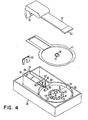
- FIG. 4 illustrates the base casting 10 in which the hub-disk assembly rotates within an enclosure defined by the cylindrical wall 80 and the actuator 30 resides in the elongated space extending from the disk enclosure.
- the shroud or baffle 28 is received in slots 82 in base 10 to provide a reduced opening at the juncture of the two enclosed spaces.
- the actuator housing 30 has a projection 83 that supports one of the ways upon which the carriage 84 reciprocates to position the transducer 85 and transducer support 86 with respect to the disk surface.
- the carriage 84 supports one transducer support 86 and one transducer 85 in data transfer relation to each of the four data surfaces on the two disks shown.
- Top cover 11 encloses the disk assembly enclosure area and the actuator enclosure area.
- the filter-breather assembly 32 is secured to base 10 and top cover 11 to provide the recircplat- ing air passageway and the filtered communication with breather opening 42.
- the filter-breather assembly opening 38 communicates with the top cover opening 76 and tubular gasket 88 causes the recirculating airflow path to be directed through the actuator housing 30.
- the filter-breather assembly also has an opening 38 (showing in Fig. 1) that adjoins top cover opening 76 to return air to the axial suction opening of the impeller formed by the hub assembly.
- the hub assembly is an integral part of the rotor of the motor which also serves as the air impeller.
- the generally radial air passages defined by the vanes 44 and hub cap 20 induce an airflow from the axial suction opening 39 in the hub cap 20 to the ports 51 of the spacers 17, 18 and the spaces between hub axial projections 22.
- the outlets are adjacent each of the disk surfaces causing a radial airflow to sweep over and purge the disk surfaces.
- the radial airflow is maintained over the disk surfaces at a volume that will not interfere with the flying characteristics of the transducer heads 85 or the head carrying slider while achieving very good purging of the surfaces.
- the reduced opening in shroud 28, through which the actuator carriage 84 moves during radial seek operations, increases the air velocity in purging over the carriage to enhance particle removal or prevent particles from entering the disk assembly enclosure.
- the recirculating air path passes through the actuator 30 and the recirculating air filter 36 downstream from the actuator to assure that particulate matter does not enter the disk assembly enclosure area.
- hub 16 forms an integral part of the drive motor rotor, the passage of recirculating air over the extended surface as represented by the vanes 44 causes the air circulation to dissipate heat generated by the motor in addition to contaminant purging. Further, the location of the motor concentrically within the hub-disk assembly makes unnecessary a drive shaft opening to the disk enclosure area to thereby eliminate the sealing problems or particulate generation associated with such a drive element entry location.
Landscapes
- Motor Or Generator Frames (AREA)
- Rotational Drive Of Disk (AREA)
Applications Claiming Priority (2)
| Application Number | Priority Date | Filing Date | Title |
|---|---|---|---|
| US378967 | 1982-05-17 | ||
| US06/378,967 US4471395A (en) | 1982-05-17 | 1982-05-17 | Self-ventilated recirculating airflow system |
Publications (2)
| Publication Number | Publication Date |
|---|---|
| EP0094484A1 true EP0094484A1 (de) | 1983-11-23 |
| EP0094484B1 EP0094484B1 (de) | 1988-12-28 |
Family
ID=23495279
Family Applications (1)
| Application Number | Title | Priority Date | Filing Date |
|---|---|---|---|
| EP83102538A Expired EP0094484B1 (de) | 1982-05-17 | 1983-03-15 | Belüftungssystem mit Luftstromumlauf |
Country Status (5)
| Country | Link |
|---|---|
| US (1) | US4471395A (de) |
| EP (1) | EP0094484B1 (de) |
| JP (1) | JPS58200480A (de) |
| DE (1) | DE3378801D1 (de) |
| SG (1) | SG25691G (de) |
Cited By (9)
| Publication number | Priority date | Publication date | Assignee | Title |
|---|---|---|---|---|
| GB2221559A (en) * | 1988-07-18 | 1990-02-07 | Seagate Technology | Air filtration system for disc drives |
| GB2225895A (en) * | 1988-11-09 | 1990-06-13 | Mitsubishi Electric Corp | Magnetic disc apparatus |
| EP0361783A3 (de) * | 1988-09-27 | 1991-03-06 | International Business Machines Corporation | Plattenspeicher mit symmetrischem Gehäuse |
| US6271988B1 (en) | 1997-01-04 | 2001-08-07 | Papst Licensing Gmbh & Co. Kg | Disk storage device with improved spindle torque and acceleration |
| US6344946B1 (en) | 1997-04-01 | 2002-02-05 | Papst Licensing Gmbh | Disk storage device with improved spindle torque and acceleration |
| USRE38601E1 (en) | 1980-05-10 | 2004-09-28 | Papst Licensing, GmbH & Co. KG | Disk storage device having a radial magnetic yoke feature |
| USRE38662E1 (en) | 1980-05-10 | 2004-11-30 | Papst Licensing Gmbh & Co. Kg | Disk storage device having a sealed bearing tube |
| USRE38673E1 (en) | 1980-05-10 | 2004-12-21 | Papst Licensing Gmbh & Co. Kg | Disk storage device having a hub sealing member feature |
| USRE38772E1 (en) | 1981-03-18 | 2005-08-09 | Papst Licensing Gmbh & Co. Kg | Disk storage device having an undercut hub member |
Families Citing this family (36)
| Publication number | Priority date | Publication date | Assignee | Title |
|---|---|---|---|---|
| USRE37058E1 (en) | 1980-05-10 | 2001-02-20 | Papst Licensing Gmbh & Co. Kg | Disk storage device having contamination seals |
| DE8220180U1 (de) * | 1982-07-15 | 1982-12-02 | Basf Ag, 6700 Ludwigshafen | Informationsplattenspeicher, insbesondere magnetplattenspeicher |
| US4587645A (en) * | 1984-05-07 | 1986-05-06 | Miniscribe Corporation | Disc drive assembly |
| JPS6297195A (ja) * | 1985-10-24 | 1987-05-06 | Mitsubishi Electric Corp | 固定磁気デイスク装置 |
| KR920006892B1 (ko) * | 1986-11-07 | 1992-08-21 | 가부시기가이샤 히다찌세이사꾸쇼 | 회전원판형 기억장치 |
| GB2202076A (en) * | 1987-03-06 | 1988-09-14 | Ibm | Disc file having at least two filters |
| US4780776A (en) * | 1987-04-20 | 1988-10-25 | International Business Machines Corporation | Air flow system in a data recording disk file |
| JPH0681477B2 (ja) * | 1988-09-16 | 1994-10-12 | 日本電気株式会社 | ボイスコイルモータ用コイル組立体 |
| USH1067H (en) | 1989-05-31 | 1992-06-02 | Seagate Technology, Inc. | Breather vent assembly formed in a sealed disk drive housing |
| US5223993A (en) * | 1989-11-03 | 1993-06-29 | Conner Peripherals, Inc. | Multiple actuator disk drive |
| EP0450206B1 (de) * | 1990-04-02 | 1993-12-15 | International Business Machines Corporation | Datenplattenspeicher |
| US5089922A (en) * | 1990-07-31 | 1992-02-18 | Seagate Technology, Inc. | Disc drive motor spindle hub for holding a disc and spacer stack firmly in place |
| US5999370A (en) * | 1992-02-21 | 1999-12-07 | Quantum Corporation | Airflow generator spindle hub for aerodynamically released shipping latch for disk drive actuator |
| JPH0636546A (ja) * | 1992-07-14 | 1994-02-10 | Nec Corp | 磁気ディスク装置 |
| US5980616A (en) * | 1993-02-16 | 1999-11-09 | Donaldson Company, Inc. | Filter media for preventing carbon migration |
| JP2553316B2 (ja) * | 1993-03-02 | 1996-11-13 | インターナショナル・ビジネス・マシーンズ・コーポレイション | データ記憶ディスク・ドライブ装置 |
| US5457589A (en) * | 1994-03-02 | 1995-10-10 | Seagate Technology, Inc. | Hub-disc interface reducing hub reloaded disc surface curvature |
| US5696649A (en) * | 1995-05-22 | 1997-12-09 | International Business Machines Corporation | Elastic insert shroud to provide maximum effective shrouding shock mitigation and filtering in high speed disk drives |
| JPH11513519A (ja) * | 1995-09-21 | 1999-11-16 | アイオメガ コーポレイション | 磁気テープドライブ用熱拡散器 |
| US6143058A (en) * | 1997-03-17 | 2000-11-07 | Donaldson Company, Inc. | Adsorbent construction and method |
| US5876487A (en) * | 1997-03-17 | 1999-03-02 | Donaldson Company, Inc. | Adsorbent construction; and, method |
| US6168651B1 (en) | 1998-10-08 | 2001-01-02 | Donaldson Company, Inc. | Filter assembly with shaped adsorbent article; and devices and methods of use |
| US6146446A (en) * | 1998-10-08 | 2000-11-14 | Donaldson Company, Inc. | Filter assembly with shaped adsorbent article; and devices and methods of use |
| US6456454B1 (en) * | 1999-10-12 | 2002-09-24 | Seagate Technology Llc | Head disc assembly having low internal air pressure |
| KR100839806B1 (ko) * | 2000-08-16 | 2008-06-19 | 도널드선 컴파니 인코포레이티드 | 디스크 드라이브용 필터 구조체 및 사용 방법 |
| US6594108B2 (en) | 2001-06-28 | 2003-07-15 | Seagate Technology Llc | Disc drive with converging filter inlet for faster cleanup times |
| US6882500B2 (en) * | 2001-10-26 | 2005-04-19 | Seagate Technology Llc | Airflow channel within a disc drive housing |
| US6959586B2 (en) | 2001-11-07 | 2005-11-01 | Seagate Technology Llc | Evaluating data handling devices by means of a marker impurity |
| US6610123B2 (en) * | 2001-12-17 | 2003-08-26 | Intel Corporation | Filtered mask enclosure |
| CN1226744C (zh) * | 2002-05-03 | 2005-11-09 | 三星电子株式会社 | 有盘保护器和磁头保护器的硬盘驱动器 |
| US6898048B2 (en) * | 2002-05-13 | 2005-05-24 | Seagate Technology Llc | Plenum assembly which filters multiple fluidic current channels using a single recirculation filter |
| JP2004185662A (ja) * | 2002-11-29 | 2004-07-02 | Agilent Technologies Japan Ltd | 検査装置用送風装置及びそれを備えた検査装置筐体 |
| US7404836B2 (en) * | 2003-05-12 | 2008-07-29 | Donaldson Company, Inc. | Focused flow filter |
| SG121815A1 (en) * | 2003-10-30 | 2006-05-26 | Seagate Technology Llc | Improved mounting configuration for a filtration canister |
| US7633708B2 (en) * | 2005-04-25 | 2009-12-15 | Hitachi Global Storage Technologies Netherlands B.V. | Collapsible bypass channel disposed outside of disk drive housing |
| US20080151492A1 (en) * | 2006-12-26 | 2008-06-26 | Maddox Charles W | Computer case with intake filter with positive airflow |
Citations (8)
| Publication number | Priority date | Publication date | Assignee | Title |
|---|---|---|---|---|
| US3688289A (en) * | 1970-05-13 | 1972-08-29 | Georg Schnell | Magnetic disc pack and arrangement for aerating the same |
| US4092687A (en) * | 1976-09-07 | 1978-05-30 | Sycor, Inc. | Disc file assembly |
| US4194225A (en) * | 1978-06-06 | 1980-03-18 | International Memories, Inc. | Housing for disk drive unit |
| GB2040538A (en) * | 1979-01-26 | 1980-08-28 | Priam Corp | Enclosed disc drive with improved air flow |
| GB2051458A (en) * | 1979-06-04 | 1981-01-14 | Memorex Mini Disc Drive Corp | Method of improving air flow in compact magnetic recordingdisc drice |
| FR2477749A1 (fr) * | 1980-03-05 | 1981-09-11 | Papst Motoren Gmbh & Co Kg | Dispositif d'entrainement avec joints d'etancheite pour memoire magnetique a plaques fixes, ou pour memoire a disque |
| US4317146A (en) * | 1979-12-03 | 1982-02-23 | Micropolis Corporation | Compact magnetic disk storage system |
| EP0063607A1 (de) * | 1980-10-29 | 1982-11-03 | Fujitsu Limited | Magnetische platteneinheit |
Family Cites Families (5)
| Publication number | Priority date | Publication date | Assignee | Title |
|---|---|---|---|---|
| JPS5273009A (en) * | 1975-12-15 | 1977-06-18 | Fujitsu Ltd | Air circulating system |
| JPS56101679A (en) * | 1980-01-18 | 1981-08-14 | Nec Corp | Magnetic disk device |
| US4367502A (en) * | 1980-04-11 | 1983-01-04 | Shugart Technology | Fixed hard disc drive assembly and clean air system |
| JPS6059663B2 (ja) * | 1980-04-16 | 1985-12-26 | 株式会社日立製作所 | 磁気ディスク記憶装置 |
| US4396964A (en) * | 1980-07-02 | 1983-08-02 | Storage Technology Corporation | Recirculating air system for magnetic disk drive |
-
1982
- 1982-05-17 US US06/378,967 patent/US4471395A/en not_active Expired - Lifetime
-
1983
- 1983-03-15 DE DE8383102538T patent/DE3378801D1/de not_active Expired
- 1983-03-15 EP EP83102538A patent/EP0094484B1/de not_active Expired
- 1983-03-18 JP JP58044593A patent/JPS58200480A/ja active Pending
-
1991
- 1991-04-05 SG SG256/91A patent/SG25691G/en unknown
Patent Citations (8)
| Publication number | Priority date | Publication date | Assignee | Title |
|---|---|---|---|---|
| US3688289A (en) * | 1970-05-13 | 1972-08-29 | Georg Schnell | Magnetic disc pack and arrangement for aerating the same |
| US4092687A (en) * | 1976-09-07 | 1978-05-30 | Sycor, Inc. | Disc file assembly |
| US4194225A (en) * | 1978-06-06 | 1980-03-18 | International Memories, Inc. | Housing for disk drive unit |
| GB2040538A (en) * | 1979-01-26 | 1980-08-28 | Priam Corp | Enclosed disc drive with improved air flow |
| GB2051458A (en) * | 1979-06-04 | 1981-01-14 | Memorex Mini Disc Drive Corp | Method of improving air flow in compact magnetic recordingdisc drice |
| US4317146A (en) * | 1979-12-03 | 1982-02-23 | Micropolis Corporation | Compact magnetic disk storage system |
| FR2477749A1 (fr) * | 1980-03-05 | 1981-09-11 | Papst Motoren Gmbh & Co Kg | Dispositif d'entrainement avec joints d'etancheite pour memoire magnetique a plaques fixes, ou pour memoire a disque |
| EP0063607A1 (de) * | 1980-10-29 | 1982-11-03 | Fujitsu Limited | Magnetische platteneinheit |
Non-Patent Citations (1)
| Title |
|---|
| Patent Abstracts of Japan vol. 5, no. 173, 5 November 1981 & JP-A-56-101679 * |
Cited By (9)
| Publication number | Priority date | Publication date | Assignee | Title |
|---|---|---|---|---|
| USRE38601E1 (en) | 1980-05-10 | 2004-09-28 | Papst Licensing, GmbH & Co. KG | Disk storage device having a radial magnetic yoke feature |
| USRE38662E1 (en) | 1980-05-10 | 2004-11-30 | Papst Licensing Gmbh & Co. Kg | Disk storage device having a sealed bearing tube |
| USRE38673E1 (en) | 1980-05-10 | 2004-12-21 | Papst Licensing Gmbh & Co. Kg | Disk storage device having a hub sealing member feature |
| USRE38772E1 (en) | 1981-03-18 | 2005-08-09 | Papst Licensing Gmbh & Co. Kg | Disk storage device having an undercut hub member |
| GB2221559A (en) * | 1988-07-18 | 1990-02-07 | Seagate Technology | Air filtration system for disc drives |
| EP0361783A3 (de) * | 1988-09-27 | 1991-03-06 | International Business Machines Corporation | Plattenspeicher mit symmetrischem Gehäuse |
| GB2225895A (en) * | 1988-11-09 | 1990-06-13 | Mitsubishi Electric Corp | Magnetic disc apparatus |
| US6271988B1 (en) | 1997-01-04 | 2001-08-07 | Papst Licensing Gmbh & Co. Kg | Disk storage device with improved spindle torque and acceleration |
| US6344946B1 (en) | 1997-04-01 | 2002-02-05 | Papst Licensing Gmbh | Disk storage device with improved spindle torque and acceleration |
Also Published As
| Publication number | Publication date |
|---|---|
| US4471395A (en) | 1984-09-11 |
| JPS58200480A (ja) | 1983-11-22 |
| SG25691G (en) | 1991-06-21 |
| DE3378801D1 (en) | 1989-02-02 |
| EP0094484B1 (de) | 1988-12-28 |
Similar Documents
| Publication | Publication Date | Title |
|---|---|---|
| EP0094484B1 (de) | Belüftungssystem mit Luftstromumlauf | |
| EP0169352B1 (de) | Datenplattenantrieb mit eingebauter Luftzirkulationsfilteranordnung | |
| US4780776A (en) | Air flow system in a data recording disk file | |
| US4054931A (en) | Gas filtering arrangement for magnetic disk information storage apparatus | |
| CA1154528A (en) | Fixed hard disc drive assembly and clean air system | |
| US4130845A (en) | Disc cabinet recirculating air flow system | |
| JPS63104287A (ja) | 防塵機構 | |
| JPS58215772A (ja) | デイスク・フアイル組立体 | |
| JP2668840B2 (ja) | 磁気ディスク・アセンブリ及びその空気濾過装置 | |
| US4710830A (en) | Sealed disc drive assembly with internal air filter | |
| EP0020933B1 (de) | Regelung der relativen Feuchtigkeit in Plattenspeichereinheiten | |
| EP0244525B1 (de) | Plattenspeicher mit Luftfiltrierungsanlage | |
| US5179483A (en) | Method for controlling airflow through a disc file spindle | |
| JPH08129871A (ja) | ディスク装置の循環フィルタ取付構造 | |
| JPH02252185A (ja) | 磁気デイスク装置 | |
| JPH0432477B2 (de) | ||
| JPS61269287A (ja) | 磁気デイスク装置 | |
| JPS5972680A (ja) | 磁気ディスク装置 | |
| JPH0679436B2 (ja) | 磁気デイスク装置 | |
| JPS61123059A (ja) | 磁気デイスク装置 | |
| JPH0636547A (ja) | ディスク装置の冷却構造 | |
| JPS63268182A (ja) | 磁気デイスク装置 | |
| JPH02130787A (ja) | 磁気ディスク装置 | |
| JPH09198781A (ja) | 磁気ディスク装置 |
Legal Events
| Date | Code | Title | Description |
|---|---|---|---|
| PUAI | Public reference made under article 153(3) epc to a published international application that has entered the european phase |
Free format text: ORIGINAL CODE: 0009012 |
|
| AK | Designated contracting states |
Designated state(s): DE FR GB |
|
| 17P | Request for examination filed |
Effective date: 19840320 |
|
| GRAA | (expected) grant |
Free format text: ORIGINAL CODE: 0009210 |
|
| AK | Designated contracting states |
Kind code of ref document: B1 Designated state(s): DE FR GB |
|
| REF | Corresponds to: |
Ref document number: 3378801 Country of ref document: DE Date of ref document: 19890202 |
|
| ET | Fr: translation filed | ||
| PLBE | No opposition filed within time limit |
Free format text: ORIGINAL CODE: 0009261 |
|
| STAA | Information on the status of an ep patent application or granted ep patent |
Free format text: STATUS: NO OPPOSITION FILED WITHIN TIME LIMIT |
|
| 26N | No opposition filed | ||
| PGFP | Annual fee paid to national office [announced via postgrant information from national office to epo] |
Ref country code: GB Payment date: 19950227 Year of fee payment: 13 |
|
| PGFP | Annual fee paid to national office [announced via postgrant information from national office to epo] |
Ref country code: FR Payment date: 19950228 Year of fee payment: 13 |
|
| PGFP | Annual fee paid to national office [announced via postgrant information from national office to epo] |
Ref country code: DE Payment date: 19950330 Year of fee payment: 13 |
|
| PG25 | Lapsed in a contracting state [announced via postgrant information from national office to epo] |
Ref country code: GB Effective date: 19960315 |
|
| GBPC | Gb: european patent ceased through non-payment of renewal fee |
Effective date: 19960315 |
|
| PG25 | Lapsed in a contracting state [announced via postgrant information from national office to epo] |
Ref country code: FR Effective date: 19961129 |
|
| PG25 | Lapsed in a contracting state [announced via postgrant information from national office to epo] |
Ref country code: DE Effective date: 19961203 |
|
| REG | Reference to a national code |
Ref country code: FR Ref legal event code: ST |