EP0093895B1 - Perkussionsinstrument - Google Patents
Perkussionsinstrument Download PDFInfo
- Publication number
- EP0093895B1 EP0093895B1 EP83103680A EP83103680A EP0093895B1 EP 0093895 B1 EP0093895 B1 EP 0093895B1 EP 83103680 A EP83103680 A EP 83103680A EP 83103680 A EP83103680 A EP 83103680A EP 0093895 B1 EP0093895 B1 EP 0093895B1
- Authority
- EP
- European Patent Office
- Prior art keywords
- plunger
- speed
- instrument
- coil
- percussion instrument
- Prior art date
- Legal status (The legal status is an assumption and is not a legal conclusion. Google has not performed a legal analysis and makes no representation as to the accuracy of the status listed.)
- Expired
Links
Images


Classifications
-
- A—HUMAN NECESSITIES
- A61—MEDICAL OR VETERINARY SCIENCE; HYGIENE
- A61B—DIAGNOSIS; SURGERY; IDENTIFICATION
- A61B9/00—Instruments for examination by percussion; Pleximeters
- A61B9/005—Electric apparatus for detecting reflex action, e.g. monitoring depth of anaesthesia
-
- A—HUMAN NECESSITIES
- A61—MEDICAL OR VETERINARY SCIENCE; HYGIENE
- A61B—DIAGNOSIS; SURGERY; IDENTIFICATION
- A61B5/00—Measuring for diagnostic purposes; Identification of persons
- A61B5/103—Measuring devices for testing the shape, pattern, colour, size or movement of the body or parts thereof, for diagnostic purposes
- A61B5/11—Measuring movement of the entire body or parts thereof, e.g. head or hand tremor or mobility of a limb
- A61B5/1104—Measuring movement of the entire body or parts thereof, e.g. head or hand tremor or mobility of a limb induced by stimuli or drugs
-
- A—HUMAN NECESSITIES
- A61—MEDICAL OR VETERINARY SCIENCE; HYGIENE
- A61B—DIAGNOSIS; SURGERY; IDENTIFICATION
- A61B9/00—Instruments for examination by percussion; Pleximeters
-
- G—PHYSICS
- G01—MEASURING; TESTING
- G01N—INVESTIGATING OR ANALYSING MATERIALS BY DETERMINING THEIR CHEMICAL OR PHYSICAL PROPERTIES
- G01N3/00—Investigating strength properties of solid materials by application of mechanical stress
- G01N3/30—Investigating strength properties of solid materials by application of mechanical stress by applying a single impulsive force, e.g. by falling weight
- G01N3/303—Investigating strength properties of solid materials by application of mechanical stress by applying a single impulsive force, e.g. by falling weight generated only by free-falling weight
-
- G—PHYSICS
- G01—MEASURING; TESTING
- G01N—INVESTIGATING OR ANALYSING MATERIALS BY DETERMINING THEIR CHEMICAL OR PHYSICAL PROPERTIES
- G01N3/00—Investigating strength properties of solid materials by application of mechanical stress
- G01N3/30—Investigating strength properties of solid materials by application of mechanical stress by applying a single impulsive force, e.g. by falling weight
- G01N3/317—Investigating strength properties of solid materials by application of mechanical stress by applying a single impulsive force, e.g. by falling weight generated by electromagnetic means
-
- A—HUMAN NECESSITIES
- A61—MEDICAL OR VETERINARY SCIENCE; HYGIENE
- A61B—DIAGNOSIS; SURGERY; IDENTIFICATION
- A61B5/00—Measuring for diagnostic purposes; Identification of persons
- A61B5/103—Measuring devices for testing the shape, pattern, colour, size or movement of the body or parts thereof, for diagnostic purposes
- A61B5/11—Measuring movement of the entire body or parts thereof, e.g. head or hand tremor or mobility of a limb
- A61B5/1111—Detecting tooth mobility
-
- A—HUMAN NECESSITIES
- A61—MEDICAL OR VETERINARY SCIENCE; HYGIENE
- A61B—DIAGNOSIS; SURGERY; IDENTIFICATION
- A61B5/00—Measuring for diagnostic purposes; Identification of persons
- A61B5/68—Arrangements of detecting, measuring or recording means, e.g. sensors, in relation to patient
- A61B5/6801—Arrangements of detecting, measuring or recording means, e.g. sensors, in relation to patient specially adapted to be attached to or worn on the body surface
- A61B5/6813—Specially adapted to be attached to a specific body part
- A61B5/6814—Head
- A61B5/682—Mouth, e.g., oral cavity; tongue; Lips; Teeth
-
- G—PHYSICS
- G01—MEASURING; TESTING
- G01N—INVESTIGATING OR ANALYSING MATERIALS BY DETERMINING THEIR CHEMICAL OR PHYSICAL PROPERTIES
- G01N2203/00—Investigating strength properties of solid materials by application of mechanical stress
- G01N2203/0058—Kind of property studied
- G01N2203/0089—Biorheological properties
-
- G—PHYSICS
- G01—MEASURING; TESTING
- G01N—INVESTIGATING OR ANALYSING MATERIALS BY DETERMINING THEIR CHEMICAL OR PHYSICAL PROPERTIES
- G01N2203/00—Investigating strength properties of solid materials by application of mechanical stress
- G01N2203/02—Details not specific for a particular testing method
- G01N2203/06—Indicating or recording means; Sensing means
- G01N2203/0617—Electrical or magnetic indicating, recording or sensing means
- G01N2203/0623—Electrical or magnetic indicating, recording or sensing means using piezoelectric gauges
Definitions
- the invention relates to a percussion instrument with an instrument housing designed as a handpiece, in which a plunger made of soft magnetic material containing a test head is movably mounted at one end and is subjected to a magnetic drive which contains a drive coil concentrically surrounding the plunger, which consists of Successive current pulses are supplied to a control electronics, whereby the tappet emerging at one end of the instrument housing is accelerated to a defined speed and, with the drive coil switched off, the plunger is moved back to its starting position in free flight at a constant speed by means of the magnetic drive, and with devices for Measurement and evaluation of signals occurring when the ram moves.
- the plunger is accelerated to a specific speed by a spiral spring arranged in the front part of the instrument containing the test head and held in the starting position by means of a magnetic coil.
- the tappet detaches from it and, guided in bearings, flies towards the body under test in free flight at a theoretically constant speed.
- the ram is thrown back towards the starting position by the counter impulse that arises.
- the coil receives a current pulse again.
- the resulting magnetic field brings the plunger back to its original position and the spring is tensioned again.
- An accelerometer connected to the plunger via a flexible cable forms a change in speed when the plunger impacts the object to be tested. This change in speed on the object to be tested can be evaluated during the deflection and reset movement for specific test and diagnostic purposes in an evaluation electronics connected to the accelerometer.
- an evaluation electronics connected to the accelerometer.
- dentistry for example, to record the mobility or degree of loosening of a tooth. The time within which the tooth to be tested is deflected by the plunger after the pulse has been given and returned to its starting position provides information about the condition of the tooth holding apparatus.
- the speed of the plunger is recorded with the aid of a measuring device, in the exemplary embodiment shown in the form of a permanent magnet attached to the movable plunger and a sensor coil interacting with it, immediately before and after the impact of the test heads and evaluated in an evaluation device in such a way that a measure can be taken from it derive for the quality of the adhesive connection, and can thus determine, among other things, unwanted air pockets.
- a measuring device in the exemplary embodiment shown in the form of a permanent magnet attached to the movable plunger and a sensor coil interacting with it, immediately before and after the impact of the test heads and evaluated in an evaluation device in such a way that a measure can be taken from it derive for the quality of the adhesive connection, and can thus determine, among other things, unwanted air pockets.
- the object of the present invention is to improve a percussion instrument of the type mentioned at the outset such that the plunger always passes into the free-flight phase at the same speed with each impact, so that the plunger speed at the end of the acceleration phase, even when the instrument is held at an angle, unaffected by the Acceleration due to gravity is largely constant.
- the plunger contains at least two adjacent sections made of non-magnetic on the one hand and soft-magnetic material on the other hand, of which the latter in the initial position of the plunger up to approximately half the length of the Immersed in the drive coil, that the drive coil concentrically surrounding the plunger accelerates it to the defined speed, that there is a measuring device that measures the size of the plunger speed during the acceleration process, the signals of which are fed to an evaluation device that provides a comparison circuit with a comparison of target and actual values for the plunger speed contains, and that there are also switching means in the drive circuit which are controlled by the comparator circuit and switch off the power supply to the drive coil when the desired speed is reached.
- the drive can consist of two drive coils in a known manner; However, it is particularly advantageous to provide only a single drive coil in connection with a permanent magnet body arranged at the plunger end and to switch the polarity of the current pulses for the drive coil in succession.
- the ram speed can either be obtained via a separate measuring coil or via an integration stage from an accelerometer attached to the ram. In the latter case, the measuring coil can be omitted. If, as is proposed according to a further advantageous embodiment of the invention, one or more platelet-shaped piezoelectric elements arranged in planes transverse to the longitudinal axis of the ram, e.g.
- Piezoceramic disks known per se provided that these are arranged in the front plunger section containing the test head, or in the test head itself, can both considerably reduce the effort for the production of the accelerometers and also realize the signal generation more effectively. Because of the different masses that act on the piezoceramic disks during impact and during the backward movement, namely on the one hand a relatively large mass on impact and on the other hand a very small mass when returning the ram, useful signals can be obtained by several powers than with one Arrangement of the accelerometer at the other end of the plunger, for example. If you want to do without an accelerometer, the acceleration signals can also be obtained via a differentiating stage from the measuring and evaluation electronics, i.e. in connection with the measuring coil. This solution has the advantage that the tappet becomes lighter due to the omission of the accelerometer and no connecting cable is required.
- the control electronics advantageously supply a current which compensates the bearing friction in the free-flight phase of the tappet, in that a drop in speed is measured in a measuring device and is compensated for by a higher current.
- a particularly advantageous embodiment of the invention takes into account a different instrument holder with respect to the horizontal, in that the control electronics contain a limit indicator for a maximum and minimum plunger speed in the free flight phase that takes into account the inclination of the instrument relative to the horizontal, and by the limit indicator when the maximum or undershoot is exceeded the minimum ram speed activated signal transmitters are available. Extreme inclined positions of the instrument, for example deviations of more than approx. ⁇ 10 ° from the horizontal, which would lead to a strong change in the plunger speed in the free flight phase, can thus be indicated to the user for a necessary correction of the instrument position.
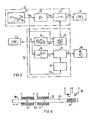
- Fig. 1 shows the percussion instrument according to the invention in longitudinal section with the associated circuit, which is shown simplified and schematically in this figure.
- a plunger 2 is mounted so that it can move largely without friction.
- the plunger 2 contains a section 2a of non-magnetic material, e.g. Aluminum, and a section 2b of soft magnetic material.
- the plunger 2 is in an end position in which its front end, which contains the test head 3, protrudes from the tapered housing end 4.
- An O-ring 5 serves as a stop, which bears against the shoulder of a sleeve 7 arranged in the instrument housing 1 between the plunger section 2b and a magnetic body 6 firmly connected to the latter.
- a flux guide piece 8 and an acceleration sensor 9 are fixedly arranged on the magnetic body 6.
- the sleeve 7 is formed in one piece and bil det two sections 7a, 7b lying concentrically to each other.
- a drive coil 10 is arranged around the sleeve section 7a and a measuring coil 11 is arranged around the sleeve section 7b.
- the drive coil 10 is connected via a line to control electronics 12, the measuring coil 11 to an evaluation device 13, and the acceleration sensor 9 to evaluation electronics 14, shown schematically in the illustration, in which the acceleration signals when the test head 3 strikes the object to be tested (e.g. on the Tooth) can be removed and processed.
- the lines mentioned run in the usual way within the instrument housing to a connection part 15, from where they are led to a unit located outside the instrument.
- the plunger 2 contains, in the front section 2a, a pin 16 extending transversely to the plunger axis, which is guided within the plunger stroke in a dovetail-shaped groove 17 of a ring 18 held in the housing part 4 (FIG. 2).
- This type of anti-rotation device is largely free of friction.
- the drive coil 10 is arranged such that the transition from section 2a to section 2b is located approximately in the middle of the drive coil in the drawn front end position of the plunger 2. Due to the combination of the magnetic coil on the one hand and the permanent magnet on the other hand, by reversing the polarity of the current pulses through the drive coil 10, these can be used both for forward and backward movement of the plunger 2. Cobalt samarium has proven to be particularly advantageous as the magnetic material for the permanent magnet 6; in particular because, owing to the high magnetic energy product and the high coercive field strength of this magnetic material, an iron yoke around the coil can be dispensed with. The construction diameter can be kept very small, especially in the front area of the instrument.
- the magnetic body 6 also contributes to increasing the forward movement of the plunger.
- the flux guide piece 8 is intended to direct and concentrate the magnetic flux through the measuring coil 11, so that the voltage induced in the measuring coil 11 by the moving magnet can be used as an output variable for measuring the plunger speed.
- a display unit which can be acoustically or optically active and which processes the signals obtained from the measuring coil and evaluated in the evaluation device 13 for a display.
- an optical and / or acoustic display is provided.
- the control electronics 12 contains a pulse generator 21, which delivers a positive signal (+ U s p) for a forward movement of the plunger to the drive coil 10 and a negative signal (- U s p) for the backward movement.
- the subsequent amplifier stage 22 with the switch 23 switches the current for the drive coil 10 accordingly.
- the switch 23 interrupts the drive current during the forward movement (clock pulse of the pulse generator 21) when the plunger 2 has reached its desired speed.
- the speed signal of the measuring coil 11 is compared in the target / actual value comparator 24 with a predetermined target value.
- the switching command generator 25 opens the switch 23 when the speed difference (Av) is zero and the pulse generator voltage is greater than zero.
- the speed signal v is simultaneously fed to a limit value detector 26, which measures when the permissible deviations from the target speed are exceeded during the free-flight phase of the plunger (clock 11 of the pulse generator) and in this case visually or acoustically detects the user of the handpiece via the display unit (signal generator) 20 indicates an improper inclined position of the instrument.
- the speed of the ram is measured and compared with the target speed.
- the drive pulse is switched off at the exact moment when the ram has reached its target speed.
- the drive pulses can be of different lengths. If the instrument is held very obliquely, the desired speed will be reached earlier than if the incline is less inclined; Accordingly, the duration of the drive pulse is greater with a less inclined instrument than with a strong incline. Even during the free flight phase, the ram speed will slow down or increase depending on the inclination of the instrument. 4 and 5, two different positions are recorded with the associated diagrams.
- the electronic circuit shown in FIG. 3 detects the deviation of the speed from the target speed and If a specified permissible limit value is exceeded during the free flight phase, this improper posture is indicated optically or acoustically.
- the plunger drive can also be carried out by a double coil, as shown schematically in Fig. 6 is.
- the plunger 30 here consists of two sections 30a, 30c made of non-magnetic material and an intermediate plunger section 30b made of soft iron. Covering the transition between the two sections, a drive coil 31 and a retraction coil 32 are arranged one behind the other in the instrument housing.
- the plunger 30 is also provided with a marking 33 which interacts with a reflex light barrier 34 arranged in the instrument housing. The speed of the plunger 30 can thus be optically recorded.
- the construction and control of the coils are carried out in the same way as described above.
- the differentiating stage 35 is connected to the measuring and evaluation device 13 and converts the speed signals obtained via the measuring coil 11 into acceleration signals, which are then further processed in the evaluation electronics 14 in a known manner.
- the advantage of this solution is that there is no need for an accelerometer.
- the speed signals are further processed in the evaluation device 13 in the manner described above.
- a particularly simple, in particular cost-effective design of the acceleration sensor with high efficiency with regard to the acceleration signals to be obtained can be achieved if the acceleration sensor is not arranged in the rear but in the front plunger section, preferably in the test head itself, in the form of one or more, the pestle is divided into piezoceramic material which divides the mass into different masses.
Landscapes
- Health & Medical Sciences (AREA)
- Life Sciences & Earth Sciences (AREA)
- Physics & Mathematics (AREA)
- General Health & Medical Sciences (AREA)
- Engineering & Computer Science (AREA)
- Veterinary Medicine (AREA)
- Pathology (AREA)
- Heart & Thoracic Surgery (AREA)
- Medical Informatics (AREA)
- Molecular Biology (AREA)
- Surgery (AREA)
- Animal Behavior & Ethology (AREA)
- Biophysics (AREA)
- Public Health (AREA)
- Biomedical Technology (AREA)
- Chemical & Material Sciences (AREA)
- Biochemistry (AREA)
- Immunology (AREA)
- General Physics & Mathematics (AREA)
- Analytical Chemistry (AREA)
- Oral & Maxillofacial Surgery (AREA)
- Bioinformatics & Cheminformatics (AREA)
- Electromagnetism (AREA)
- Dentistry (AREA)
- Anesthesiology (AREA)
- Physiology (AREA)
- Medicinal Chemistry (AREA)
- Apparatuses For Generation Of Mechanical Vibrations (AREA)
- Dental Tools And Instruments Or Auxiliary Dental Instruments (AREA)
- Investigating Strength Of Materials By Application Of Mechanical Stress (AREA)
- Electrophonic Musical Instruments (AREA)
Priority Applications (1)
| Application Number | Priority Date | Filing Date | Title |
|---|---|---|---|
| AT83103680T ATE24766T1 (de) | 1982-04-26 | 1983-04-15 | Perkussionsinstrument. |
Applications Claiming Priority (2)
| Application Number | Priority Date | Filing Date | Title |
|---|---|---|---|
| DE19823215530 DE3215530A1 (de) | 1982-04-26 | 1982-04-26 | Perkussionsinstrument |
| DE3215530 | 1982-04-26 |
Publications (2)
| Publication Number | Publication Date |
|---|---|
| EP0093895A1 EP0093895A1 (de) | 1983-11-16 |
| EP0093895B1 true EP0093895B1 (de) | 1987-01-07 |
Family
ID=6161981
Family Applications (1)
| Application Number | Title | Priority Date | Filing Date |
|---|---|---|---|
| EP83103680A Expired EP0093895B1 (de) | 1982-04-26 | 1983-04-15 | Perkussionsinstrument |
Country Status (5)
| Country | Link |
|---|---|
| US (1) | US4499906A (enExample) |
| EP (1) | EP0093895B1 (enExample) |
| JP (1) | JPS58192536A (enExample) |
| AT (1) | ATE24766T1 (enExample) |
| DE (2) | DE3215530A1 (enExample) |
Families Citing this family (29)
| Publication number | Priority date | Publication date | Assignee | Title |
|---|---|---|---|---|
| US4689011A (en) * | 1984-12-13 | 1987-08-25 | Siemens Aktiengesellschaft | Dental percussion instrument |
| US4713962A (en) * | 1984-12-13 | 1987-12-22 | Siemens Aktiengesellschaft | Test device for a dental percussion instrument |
| US4682490A (en) * | 1985-01-31 | 1987-07-28 | Adelman Roger A | Impact test instrument |
| US4711754A (en) * | 1985-10-18 | 1987-12-08 | Westinghouse Electric Corp. | Method and apparatus for impacting a surface with a controlled impact energy |
| US4764114A (en) * | 1986-01-13 | 1988-08-16 | Foster-Miller, Inc. | Analysis system |
| JPS63100991A (ja) * | 1987-01-29 | 1988-05-06 | 日本マグネテイツクス株式会社 | ハンマリング装置 |
| US4881552A (en) * | 1988-01-20 | 1989-11-21 | Measurement Resources Inc. | Tooth stability monitor |
| SE465550B (sv) * | 1990-01-29 | 1991-09-30 | Bioapatite Ab | Apparat foer diagnostik i samband med parodontit |
| US5518008A (en) * | 1994-08-25 | 1996-05-21 | Spectral Sciences Research Corporation | Structural analyzer, in particular for medical implants |
| US5803730A (en) * | 1996-03-15 | 1998-09-08 | Khademazad; Behrooz | Mobilometer |
| US6120466A (en) * | 1996-12-27 | 2000-09-19 | James C. Earthman | System and method for quantitative measurements of energy damping capacity |
| FR2761777B1 (fr) * | 1997-04-08 | 1999-06-11 | Univ Nantes | Dispositif, en particulier pour la mesure de la resistance a la rupture de granules ou similaires |
| US6030221A (en) * | 1998-02-11 | 2000-02-29 | Cavitat, Inc. | Ultrasonic apparatus and for precisely locating cavitations within jawbones and the like |
| US6565554B1 (en) * | 1999-04-07 | 2003-05-20 | Intuitive Surgical, Inc. | Friction compensation in a minimally invasive surgical apparatus |
| SE9903304L (sv) * | 1999-09-16 | 2001-03-17 | Integration Diagnostics Ltd | Anordning och metod för implantat beläget i ben |
| US20050137473A1 (en) * | 2002-06-17 | 2005-06-23 | Antti Kontiola | Apparatus for measuring intraocular pressure |
| JP3706360B2 (ja) * | 2002-07-12 | 2005-10-12 | 藤栄電気株式会社 | 歯牙動揺度測定装置、同装置の動作方法、及び同装置に使用されるノズル |
| US6997887B2 (en) * | 2002-09-27 | 2006-02-14 | Earthman James C | Evaluation of reflected time-energy profile for determination of damping capacity |
| US7008385B2 (en) * | 2002-09-27 | 2006-03-07 | Earthman James C | Evaluation of reflected time-energy profile for evaluation of osseointegration and density |
| US8656759B2 (en) * | 2010-03-18 | 2014-02-25 | Innoquest, Inc. | Handheld penetrating consistometer |
| WO2011160102A2 (en) | 2010-06-19 | 2011-12-22 | Perimetrics, Llc | System and method for determining structural characteristics of an object |
| US9869606B2 (en) | 2011-06-18 | 2018-01-16 | Perimetrics, Llc | System and method for determining structural characteristics of an object |
| US9995665B2 (en) | 2015-04-03 | 2018-06-12 | Drexel University | Dynamic impact fatigue device |
| KR102472465B1 (ko) * | 2015-07-31 | 2022-11-30 | 아크로웰 주식회사 | 임플란트 동요도 측정 장치 및 그 제어 방법 |
| CA3005099A1 (en) * | 2015-11-15 | 2017-05-18 | Smile Lab Inc | Micro vibrating devices for dental use |
| WO2017117328A1 (en) * | 2015-12-29 | 2017-07-06 | Robert Coleman | System and methods for dynamic bone structure interaction |
| KR102386116B1 (ko) * | 2016-11-02 | 2022-04-22 | (주) 디엠에스 | 치과용 임플란트 동요도 측정장치의 제어방법 |
| CN110139625A (zh) * | 2016-12-30 | 2019-08-16 | 佩里梅特里克斯有限责任公司 | 用于确定对象的结构特性的系统和方法 |
| EP4354112B1 (en) * | 2017-12-30 | 2025-09-10 | Perimetrics, Inc. | Determination of structural characteristics of an object |
Citations (1)
| Publication number | Priority date | Publication date | Assignee | Title |
|---|---|---|---|---|
| DE2853252A1 (de) * | 1978-12-09 | 1980-06-19 | Walter Frenkel | Elektrisches perkussionsgeraet |
Family Cites Families (9)
| Publication number | Priority date | Publication date | Assignee | Title |
|---|---|---|---|---|
| US3094115A (en) * | 1960-06-08 | 1963-06-18 | Herbert S Polin | Tooth mobility indicator |
| US3498388A (en) * | 1967-12-05 | 1970-03-03 | Arthur Jovis | Pile driving system |
| US3653373A (en) * | 1970-01-19 | 1972-04-04 | Steven C Batterman | Apparatus for acoustically determining periodontal health |
| DE2162683C3 (de) * | 1971-12-17 | 1980-09-04 | Hugo Sachs Elektronik Kg, 7801 March | Einrichtung zur Messung des Weges eines Meßobjektes bei einer am Meßobjekt wirkenden Kraft |
| DE2617779C2 (de) * | 1976-04-23 | 1982-02-11 | Fraunhofer-Gesellschaft zur Förderung der angewandten Forschung e.V., 8000 München | Perkussionsinstrument für Diagnose- und Prüfzwecke |
| DE2733081A1 (de) * | 1977-07-22 | 1979-02-15 | Sachs Elektronik Kg Hugo | Schaltungsanordnung zum messen von zahnauslenkungen |
| US4195512A (en) * | 1977-11-03 | 1980-04-01 | The United States Of America As Represented By The Administrator Of The National Aeronautics And Space Administration | Coal-shale interface detector |
| US4289023A (en) * | 1979-09-19 | 1981-09-15 | Schlumberger Technology Corp. | Percussion method and apparatus for the investigation of a casing cement in a borehole |
| DE3115711A1 (de) * | 1981-04-18 | 1982-11-04 | Fraunhofer-Gesellschaft zur Förderung der angewandten Forschung e.V., 8000 München | "perkussionsinstrument fuer diagnose- und pruefzwecke" |
-
1982
- 1982-04-26 DE DE19823215530 patent/DE3215530A1/de not_active Withdrawn
-
1983
- 1983-04-11 US US06/483,881 patent/US4499906A/en not_active Expired - Fee Related
- 1983-04-15 EP EP83103680A patent/EP0093895B1/de not_active Expired
- 1983-04-15 AT AT83103680T patent/ATE24766T1/de not_active IP Right Cessation
- 1983-04-15 DE DE8383103680T patent/DE3368993D1/de not_active Expired
- 1983-04-25 JP JP58072769A patent/JPS58192536A/ja active Granted
Patent Citations (1)
| Publication number | Priority date | Publication date | Assignee | Title |
|---|---|---|---|---|
| DE2853252A1 (de) * | 1978-12-09 | 1980-06-19 | Walter Frenkel | Elektrisches perkussionsgeraet |
Also Published As
| Publication number | Publication date |
|---|---|
| EP0093895A1 (de) | 1983-11-16 |
| US4499906A (en) | 1985-02-19 |
| JPH0153062B2 (enExample) | 1989-11-13 |
| DE3368993D1 (en) | 1987-02-12 |
| ATE24766T1 (de) | 1987-01-15 |
| DE3215530A1 (de) | 1983-10-27 |
| JPS58192536A (ja) | 1983-11-10 |
Similar Documents
| Publication | Publication Date | Title |
|---|---|---|
| EP0093895B1 (de) | Perkussionsinstrument | |
| EP0093896B1 (de) | Perkussionsinstrument | |
| DE1912279C3 (de) | Tintentropfenschreiber | |
| DE2452880C2 (de) | Verfahren und Vorrichtung zur Härteprüfung von Werkstücken | |
| WO2003056303A1 (de) | Härtemessgerät mit einem gehäuse und einem eindringkörper, insbesondere handgerät | |
| DE2944490A1 (de) | Verfahren zur beseitigung von remanenzerscheinungen in empfangssystemen und vorrichtung zur durchfuehrungdes verfahrens | |
| CH656062A5 (de) | Zahnaerztliche handstueckanordnung. | |
| DE7731145U1 (de) | Vorrichtung zur messung des massendurchsatzes | |
| WO1983002666A1 (fr) | Dispositif permettant d'effectuer des mesures micromecaniques de la surface d'objets d'essai | |
| DE2751095B1 (de) | Haertepruefgeraet nach Shore | |
| DE2426044C3 (de) | Vorrichtung zur Steuerung der Querschnittsgröße eines kontinuierlich extrudierten nichttransparenten, langgestreckten Erzeugnisses | |
| DE202014004097U1 (de) | Vorrichtung zum Erzeugen von Kraftstößen | |
| DE19929648A1 (de) | Antriebsanordnung für Meßinstrumente und Meßinstrument mit einer derartigen Antriebsanordnung | |
| DE2803149C2 (de) | Verfahren zum Ausmessen von Härteprüfeindrücken in Materialoberflächen sowie Einrichtung zur Durchführung des Verfahrens | |
| DE3115711A1 (de) | "perkussionsinstrument fuer diagnose- und pruefzwecke" | |
| DE4428765A1 (de) | Gerät | |
| AT404881B (de) | Verfahren und vorrichtung zur prüfung der zugfestigkeit eines spröden, stabförmigen prüflings | |
| DE2131424A1 (de) | Elektromagnetischer Stellantrieb | |
| DE19609563C1 (de) | Verfahren und Einrichtung zum Markieren von Objekten | |
| DD285833A5 (de) | Mikrohaertepruefeinrichtung | |
| DE102014109849A1 (de) | Anordnung und Verfahren zum stoßwellengeführten Bewegen eines Objektes | |
| AT231560B (de) | Meßeinrichtung, bei der die Meßgröße die Frequenz bzw. Phasenlage einer Impulsfolge beeinflußt | |
| DE112004002838T5 (de) | Positionsbestimmungsvorrichtung und Verfahren zur Positionsbestimmung | |
| DE1573427A1 (de) | Drehmomentmessvorrichtung | |
| DE1598409C3 (de) | Verfahren und Vorrichtung zum Herstellen eines Korngrößenverteüungsdiagrammes eines Teilchengemisches durch Sedimentieren in einem Suspensionsmedium |
Legal Events
| Date | Code | Title | Description |
|---|---|---|---|
| PUAI | Public reference made under article 153(3) epc to a published international application that has entered the european phase |
Free format text: ORIGINAL CODE: 0009012 |
|
| AK | Designated contracting states |
Designated state(s): AT CH DE FR GB IT LI SE |
|
| 17P | Request for examination filed |
Effective date: 19840509 |
|
| RAP1 | Party data changed (applicant data changed or rights of an application transferred) |
Owner name: LUKAS, DIETER, DIPL.-PHYS. Owner name: SCHULTE, WILLI, PROF. DR. Owner name: FRAUNHOFER-GESELLSCHAFT ZUR FOERDERUNG DER ANGEWA Owner name: SIEMENS AKTIENGESELLSCHAFT |
|
| RAP1 | Party data changed (applicant data changed or rights of an application transferred) |
Owner name: LUKAS, DIETER, DIPL.-PHYS. Owner name: SCHULTE, WILLI, PROF. DR. Owner name: FRAUNHOFER-GESELLSCHAFT ZUR FOERDERUNG DER ANGEWA Owner name: SIEMENS AKTIENGESELLSCHAFT |
|
| GRAA | (expected) grant |
Free format text: ORIGINAL CODE: 0009210 |
|
| AK | Designated contracting states |
Kind code of ref document: B1 Designated state(s): AT CH DE FR GB IT LI SE |
|
| REF | Corresponds to: |
Ref document number: 24766 Country of ref document: AT Date of ref document: 19870115 Kind code of ref document: T |
|
| REF | Corresponds to: |
Ref document number: 3368993 Country of ref document: DE Date of ref document: 19870212 |
|
| ITF | It: translation for a ep patent filed | ||
| ET | Fr: translation filed | ||
| PLBE | No opposition filed within time limit |
Free format text: ORIGINAL CODE: 0009261 |
|
| STAA | Information on the status of an ep patent application or granted ep patent |
Free format text: STATUS: NO OPPOSITION FILED WITHIN TIME LIMIT |
|
| 26N | No opposition filed | ||
| ITTA | It: last paid annual fee | ||
| PGFP | Annual fee paid to national office [announced via postgrant information from national office to epo] |
Ref country code: SE Payment date: 19920429 Year of fee payment: 10 |
|
| PGFP | Annual fee paid to national office [announced via postgrant information from national office to epo] |
Ref country code: GB Payment date: 19930319 Year of fee payment: 11 |
|
| PG25 | Lapsed in a contracting state [announced via postgrant information from national office to epo] |
Ref country code: SE Effective date: 19930416 |
|
| PG25 | Lapsed in a contracting state [announced via postgrant information from national office to epo] |
Ref country code: GB Effective date: 19940415 |
|
| GBPC | Gb: european patent ceased through non-payment of renewal fee |
Effective date: 19940415 |
|
| EUG | Se: european patent has lapsed |
Ref document number: 83103680.1 Effective date: 19931110 |
|
| PGFP | Annual fee paid to national office [announced via postgrant information from national office to epo] |
Ref country code: AT Payment date: 19950324 Year of fee payment: 13 |
|
| PGFP | Annual fee paid to national office [announced via postgrant information from national office to epo] |
Ref country code: FR Payment date: 19950426 Year of fee payment: 13 |
|
| PGFP | Annual fee paid to national office [announced via postgrant information from national office to epo] |
Ref country code: DE Payment date: 19950621 Year of fee payment: 13 |
|
| PGFP | Annual fee paid to national office [announced via postgrant information from national office to epo] |
Ref country code: CH Payment date: 19950718 Year of fee payment: 13 |
|
| PG25 | Lapsed in a contracting state [announced via postgrant information from national office to epo] |
Ref country code: AT Effective date: 19960415 |
|
| PG25 | Lapsed in a contracting state [announced via postgrant information from national office to epo] |
Ref country code: LI Effective date: 19960430 Ref country code: CH Effective date: 19960430 |
|
| REG | Reference to a national code |
Ref country code: CH Ref legal event code: PL |
|
| PG25 | Lapsed in a contracting state [announced via postgrant information from national office to epo] |
Ref country code: FR Effective date: 19961227 |
|
| PG25 | Lapsed in a contracting state [announced via postgrant information from national office to epo] |
Ref country code: DE Effective date: 19970101 |
|
| REG | Reference to a national code |
Ref country code: FR Ref legal event code: ST |