EP0093867B1 - Hüftgelenk für ein künstliches Bein - Google Patents
Hüftgelenk für ein künstliches Bein Download PDFInfo
- Publication number
- EP0093867B1 EP0093867B1 EP83102934A EP83102934A EP0093867B1 EP 0093867 B1 EP0093867 B1 EP 0093867B1 EP 83102934 A EP83102934 A EP 83102934A EP 83102934 A EP83102934 A EP 83102934A EP 0093867 B1 EP0093867 B1 EP 0093867B1
- Authority
- EP
- European Patent Office
- Prior art keywords
- joint
- joint member
- hip
- angle
- wedge
- Prior art date
- Legal status (The legal status is an assumption and is not a legal conclusion. Google has not performed a legal analysis and makes no representation as to the accuracy of the status listed.)
- Expired
Links
Images

Classifications
-
- A—HUMAN NECESSITIES
- A61—MEDICAL OR VETERINARY SCIENCE; HYGIENE
- A61F—FILTERS IMPLANTABLE INTO BLOOD VESSELS; PROSTHESES; DEVICES PROVIDING PATENCY TO, OR PREVENTING COLLAPSING OF, TUBULAR STRUCTURES OF THE BODY, e.g. STENTS; ORTHOPAEDIC, NURSING OR CONTRACEPTIVE DEVICES; FOMENTATION; TREATMENT OR PROTECTION OF EYES OR EARS; BANDAGES, DRESSINGS OR ABSORBENT PADS; FIRST-AID KITS
- A61F2/00—Filters implantable into blood vessels; Prostheses, i.e. artificial substitutes or replacements for parts of the body; Appliances for connecting them with the body; Devices providing patency to, or preventing collapsing of, tubular structures of the body, e.g. stents
- A61F2/50—Prostheses not implantable in the body
- A61F2/60—Artificial legs or feet or parts thereof
- A61F2/605—Hip joints
Definitions
- the invention relates to a hip joint for an artificial leg with a mounting bracket consisting of a substantially horizontal leg and an upright leg at an obtuse angle, to which a first joint part is fastened, which is connected via a swivel joint to a second one for connection to the artificial one Leg provided joint part is connected, wherein the rotational movement of the second joint part is limited by stops for the standing and the sitting position of the artificial leg and between the first and the second joint part elastic means are used for the movement of the second joint part from the standing in the sitting position and vice versa generate an elastic counterforce.
- Such hip joints have been used for many years to movably attach a complete artificial leg to the body of the leg amputee.
- the fastening angle is generally connected to a fastening part which is strapped around the lower body of the leg amputee.
- the elastic means between the first and second joint part have the task of holding the artificial leg securely in the standing or sitting position and to enable the artificial thigh to move as naturally as possible.
- the first joint part is attached to the substantially horizontal leg of the fastening angle.
- the elastic means between the first and second joint part are formed by elastic bands which are stretched between the two joint parts or the first joint part and the artificial leg.
- the known hip joints require a relatively large amount of space. This not only leads to cosmetic difficulties, but is particularly disadvantageous in the seating position of the prosthesis wearer. When sitting, the hip joint hits the seat, so that a comfortable seat is significantly disturbed. The handling of such a hip joint is therefore not optimal.
- Older hip joints are equipped with a lock that only allows a very small amount of movement of the hip joint while walking. To take up the sitting position, the prosthesis wearer has to release the lock manually.
- the lock fulfills a locking function for the standing position.
- the invention is therefore based on the object of creating a hip joint of the type mentioned at the outset, which is easier to handle and more convenient for the prosthesis wearer and which also facilitates the cosmetic design.
- first joint part is attached to the upright leg of the fastening bracket and that the first joint part and the second joint part do not protrude, or at most only insignificantly, downward over the extension line of the essentially horizontal leg in the sitting position.
- the hip joint according to the invention has the essential advantage that it does not bother the prosthesis wearer in the sitting position at all, because it has an overall height of zero or almost zero at the bottom.
- the hip joint according to the invention can be built so compactly that it can be cosmetically fully covered.
- the first joint part By attaching the first joint part to the upright leg of the fastening bracket, the first joint part can be rotatably attached to the fastening bracket by a small angle in the vertical plane. This makes it possible to adjust the artificial leg in the hip joint in the frontal plane. While such an adjustment option is not provided in any known hip joint, the inventive hip joint can be adapted to the individual circumstances of the prosthesis wearer without the leg prosthesis itself having to be changed for this purpose.
- the first joint part has two holes arranged one below the other, through which the fastening screws for fastening protrude on the fastening bracket and one of which is designed as an arcuate elongated hole.
- the arcuate elongated hole enables the rotation of the first joint part about an almost horizontal axis, which is perpendicular to the upright leg of the mounting bracket.
- an adjustment option in the sagittal plane is preferably realized in the hip joint according to the invention in that the top side of the second joint part in the standing position abuts the underside of the first joint part and that the height of the top side of the second joint part is adjustable .
- the angle of the thigh of the artificial leg can be adjusted in the standing position.
- the upper side of the second joint part is formed by a wedge-shaped stop piece which rests on an inclined surface of a wedge-shaped counterpart and that the relative horizontal position of the two wedge-shaped pieces is adjustable.
- the horizontal position of the two wedge-shaped pieces is preferably adjusted in that one of the wedge-shaped pieces has a through hole in the horizontal direction through which a screw, which is guided in a threaded hole of the other wedge-shaped piece, projects and is mounted in the housing of the joint so as not to be displaceable in the horizontal direction .
- the screw By adjusting the screw, the hori zontal relative position of the two wedge-shaped pieces can be changed, whereby the height of the top of the wedge-shaped stop piece can be changed.
- the upper side of the second joint part is formed from an elastic, damping material.
- the hip joint according to the invention can preferably be further reduced in size by a pin rotatably mounted on the first joint part, the other end of which is rotatably connected in the second joint part to one end of a compression spring mounted in a tubular extension for a tubular skeleton part of the artificial leg.
- a compression spring mounted in a tubular extension for a tubular skeleton part of the artificial leg.
- the pivotable articulation of the pin on the first joint part is preferably carried out above the articulation point on the compression spring in the standing position and below the articulation point of the spring in the seated position. It is thereby achieved that the spring force increases over a certain range of movement angle of the hip joint, while it decreases when a certain deflection of the hip joint is exceeded. This deflection preferably affects approximately 90 °. If the hip joint has been deflected by this 90 °, the spring ensures that the further movement into the sitting position of the hip joint is facilitated by the spring force.
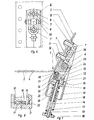
- Fig. 1 shows a mounting bracket 1, which has a substantially horizontal leg 2 and an upright leg 3 at an obtuse angle.
- the horizontal leg 2 has five through holes 4 through which fastening screws are used for attachment to a fastening part 5 which can be seen in FIGS. 5 to 7.
- fastening screws rivets or resin-impregnated laminate fibers can also be used.
- the hip joint according to the invention is screwed with a first joint part 6 to the upright leg 3 of the fastening angle by means of two screws 7.
- the first joint part 6 has two holes 8, of which the upper is designed as an arcuate elongated hole, as shown in FIG. 4.
- a washer 9 is located above the holes 8.
- a second joint part 10 is rotatably mounted on the first joint part 6 via a swivel joint 11 in the plane of the drawing in FIG. 1.
- two fork-shaped ends 12 comprise the first joint part 6 on both sides.
- the second joint part 10 is designed as a hollow tube 13 towards the free end.
- An axis 14 is arranged centrally in the hollow tube 13 and carries a thread 15 at the lower end.
- An adjusting washer 16 with an internal thread is screwed onto the thread 15.
- a pressure spring 17 is supported on the adjusting disk 16, the other end of which rests on a stop disk 18 of a sleeve 19 which is displaceable relative to the axis 14.
- the sleeve 19 is arranged within the helical compression spring 17.
- the stop disk 18 In the standing position of the hip joint, the stop disk 18 lies against an upper floor 20 of the hollow tube 13. A projection 22 of the stop disk 18 projects upwards through an opening 21 in the base 20.
- the extension 22 is fork-shaped upwards and has a receiving trough 23 in which a convex end face of a pin 24 is supported.
- the other end of the pin 24 comprises, in the form of a claw, a bearing pin 25 which is aligned parallel to the swivel joint 11.
- the pin 24 is thus rotatably mounted about the bearing pin 25 of the first swivel joint 6 and in the receiving trough 23 of the second swivel joint 10.
- the second joint part 10 lies with its top against the lower edge 26 of the first joint part 6 in the standing position.
- the top has an insert 28 made of an elastic, damping material.
- This insert is arranged in a height-adjustable manner with facial expressions, which is shown in detail in FIG. 3.
- a wedge-shaped stop piece 29 is mounted with its inclined surface on an inclined surface of a wedge-shaped counterpart 30.
- An adjusting screw 32 which is horizontally immovably mounted in the housing 31 of the second joint part 10 projects through a through opening 33 of the wedge-shaped stop part 29 and interacts with an internal thread 34 in the wedge-shaped counterpart 30. By tightening the screw 32, the wedge-shaped counterpart 30 moves to the right in the illustration in FIG. 3, as a result of which the wedge-shaped stop piece 29 is displaced upward, as is shown in broken lines in FIG. 3.
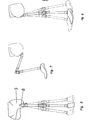
- FIG. 5 and 6 show the possibility of adjusting the hip joint according to the invention in the frontal plane and in the sagittal plane.
- the adjustment in the frontal plane is carried out with the aid of a screw 36 when the screws 7 are loosened and the circular-shaped elongated hole 8, while the adjustment in the sagittal plane (FIG. 6) is carried out with the aid of the stop piece shown in detail in FIG. 3.
- FIG 7 illustrates that the hip joint according to the invention does not protrude downwards in the sitting position, so that the wearer of the artificial leg is not disturbed by the hip joint in the sitting position.
Description
- Die Erfindung betrifft ein Hüftgelenk für ein künstliches Bein mit einem aus einem im wesentlichen horizontalen Schenkel und einem im stumpfen Winkel dazu stehenden aufrechten Schenkel bestehenden Befestigungswinkel, an dem ein erstes Gelenkteil befestigt ist, das über ein Drehgelenk mit einem zweiten, zur Verbindung mit dem künstlichen Bein vorgesehenen Gelenkteil verbunden ist, wobei die Drehbewegung des zweiten Gelenkteils durch Anschläge für die stehende und die sitzende Stellung des künstlichen Beins beschränkt ist und zwischen dem ersten und dem zweiten Gelenkteil elastische Mittel eingesetzt sind, die für die Bewegung des zweiten Gelenkteils aus der stehenden in die sitzende Stellung und umgekehrt eine elastische Gegenkraft erzeugen.
- Derartige Hüftgelenke werden seit vielen Jahren dazu benutzt, ein vollständiges künstliches Bein beweglich an dem Körper des Beinamputierten anzubringen. Der Befestigungswinkel wird dabei im allgemeinen mit einem um den Unterkörper des Beinamputierten geschnallten Befestigungsteil verbunden. Die elastischen Mittel zwischen dem ersten und zweiten Gelenkteil haben die Aufgabe, das künstliche Bein sicher in der stehenden bzw. sitzenden Stellung zu halten und eine möglichst natürliche Bewegung des künstlichen Oberschenkels zu ermöglichen.
- Bei den bekannten Hüftge'enken dieser Art ist das erste Gelenkteil an dem im wesentlichen horizontal stehenden Schenkel des Befestigungswinkels angebracht. Die elastischen Mittel zwischen dem ersten und zweiten Gelenkteil werden durch elastische Bänder gebildet, die zwischen den beiden Gelenkteilen oder dem ersten Gelenkteil und dem künstlichen Bein gespannt sind.
- Die bekannten Hüftgelenke haben einen relativ grossen Raumbedarf. Dies führt nicht nur zu kosmetischen Schwierigkeiten, sondern ist insbesondere in der Sitzposition des Prothesenträgers nachteilig. Beim Sitzen stösst nämlich das Hüftgelenk auf die Sitzfläche auf, so dass ein bequemer Sitz erheblich gestört wird. Die Handhabung eines derartigen Hüftgelenks ist daher nicht optimal.
- Hüftgelenke älterer Bauart sind mit einer Sperre versehen, die eine Bewegung des Hüftgelenkes nur in einem ganz geringen Masse während des Gehens erlauben. Um die Sitzposition einzunehmen, muss der Prothesenträger die Sperre manuell lösen. Die Sperre erfüllt eine Rastfunktion für die stehende Position. Diese Hüftgelenke sind mit den oben beschriebenen Hüftgelenken nicht vergleichbar, da sie der manuellen Handhabe jederzeit zugänglich sein müssen und die Funktion der Sperre bei den neueren Hüftgelenken durch die elastischen Mittel ausgeübt wird.
- Der Erfindung liegt daher die Aufgabe zugrunde, ein Hüftgelenk der eingangs erwähnten Art zu erstellen, das einfacher in der Handhabung und für den Prothesenträger bequemer ist und darüber hinaus die kosmetische Ausgestaltung erleichtert.
- Diese Aufgabe wird erfindungsgemäss dadurch gelöst, dass das erste Gelenkteil am aufrechten Schenkel des Befestigungswinkels angebracht ist und dass das erste Gelenkteil und das zweite Gelenkteil in der sitzenden Stellung nicht oder höchstens unwesentlich über die Verlängerungslinie des im wesentlichen horizontalen Schenkels nach unten herausragen.
- Das erfindungsgemässe Hüftgelenk weist den wesentlichen Vorteil auf, dass es den Prothesenträger in der sitzenden Stellung überhaupt nicht stört, weil es nach unten eine Bauhöhe Null oder nahezu Null aufweist. Darüber hinaus lässt sich das erfindungsgemässe Hüftgelenk so kompakt bauen, dass es kosmetisch voll verkleidbar ist.
- Durch die Anbringung des ersten Gelenkteils an dem aufrechten Schenkel des Befestigungswinkels lässt sich das erste Gelenkteil um einen kleinen Winkel in vertikaler Ebene drehbar an dem Befestigungswinkel anbringen. Dadurch ist es möglich, das künstliche Bein in dem Hüftgelenk in der Frontalebene zu justieren. Während eine derartige Verstellmöglichkeit bei keinem bekannten Hüftgelenk vorgesehen ist, kann bei dem erfindungsgemässen Hüftgelenk eine Anpassung an die individuellen Gegebenheiten des Prothesenträgers erreicht werden, ohne dass hierzu die Beinprothese selbst geändert werden müsste.
- In einer einfachen Ausgestaltungsform weist das erste Gelenkteil zwei untereinander angeordnete Löcher auf, durch die die Befestigungsschrauben zur Befestigung an dem Befestigungswinkel ragen und von denen eines als kreisbogenförmiges Langloch ausgebildet ist. Das kreisbogenförmige Langloch ermöglicht dabei die Drehung des ersten Gelenkteils um eine nahezu horizontale Achse, die senkrecht auf dem aufrechten Schenkel des Befestigungswinkels steht.
- Zusätzlich zu der Justiermöglichkeit in der Frontalebene wird bei dem erfindungsgemässen Hüftgelenk vorzugsweise eine Justiermöglichkeit in der Sagittalebene dadurch verwirklicht, dass das zweite Gelenkteil in der stehenden Stellung mit seiner Oberseite gegen die Unterseite des ersten Gelenkteils stösst und dass die Höhe der Oberseite des zweiten Gelenkteils einstellbar ist. Durch die Verstellung der Höhe der Oberseite des zweiten Gelenkteils lässt sich der Winkel des Oberschenkels des künstlichen Beins in der stehenden Stellung justieren.
- Dies geschieht in einfacher Weise dadurch, dass die Oberseite des zweiten Gelenkteils durch ein keilförmiges Anschlagstück gebildet ist, das auf einer schrägen Fläche eines keilförmigen Gegenstücks aufliegt und dass die relative horizontale Lage der beiden keilförmigen Stücke einstellbar ist. Die Verstellung der horizontalen Lage der beiden keilförmigen Stücke geschieht vorzugsweise dadurch, dass eines der keilförmigen Stücke in horizontaler Richtung ein Durchgangsloch aufweist, durch das eine in einem Gewindeloch des anderen keilförmigen Stücks geführte Schraube hindurchragt, die im Gehäuse des Gelenks in horizontaler Richtung unverschiebbar gelagert ist. Durch die Verstellung der Schraube kann die horizontale relative Position der beiden keilförmigen Stücke verändert werden, wodurch die Höhe der Oberseite des keilförmigen Anschlagstücks veränderbar ist. Zur Geräuschminderung und Dämpfung der Anschlagbewegung ist es vorteilhaft, wenn die Oberseite des zweiten Gelenkteils aus einem elastischen, dämpfenden Material gebildet ist.
- Ein wesentlicher Grund für die Unförmigkeit der bekannten Hüftgelenke lag in der Anbringung der elastischen Bänder, die üblicherweise auf beiden Seiten des Hüftgelenks angebracht worden sind. Das erfindungsgemässe Hüftgelenk lässt sich vorzugsweise weiter verkleinern durch einen drehbar am ersten Gelenkteil gelagerten Stift, dessen anderes Ende in dem zweiten Gelenkteil drehbar mit einem Ende einer in einem rohrförmigen Ansatz für ein Rohrskeletteil des künstlichen Beins gelagerten Druckfeder verbunden ist. Erfindungsgemäss lässt sich daher das für die Bewegung des Hüftgelenks erforderliche elastische Mittel ohne zusätzlichen Raumaufwand innerhalb des Gelenks im Rahmen der Rohrskelettbauweise verwirklichen, wobei die Möglichkeit der kosmetischen Verkleidung weiter verbessert wird. Die Vorspannung der Druckfeder ist vorzugsweise einstellbar, um die elastische Kraft den individuellen Gegebenheiten anpassen zu können. Bei den bekannten Hüftgelenken konnte eine derartige Anpassung nur durch Auswechslung der elastischen Bänder erfolgen.
- Die drehbare Anlenkung des Stiftes an dem ersten Gelenkteil erfolgt vorzugsweise oberhalb des Anlenkpunktes an der Druckfeder in der stehenden Stellung und unterhalb des Anlenkpunktes der Feder in der sitzenden Stellung. Dadurch wird erreicht, dass über einen gewissen Bewegungswinkelbereich des Hüftgelenks die Federkraft zunimmt, während sie abnimmt, wenn eine gewisse Auslenkung des Hüftgelenks überschritten wird. Diese Auslenkung betrifft vorzugsweise etwa 90°. Ist das Hüftgelenk um diese 90° ausgelenkt worden, sorgt die Feder dafür, dass die weitere Bewegung in die sitzende Stellung des Hüftgelenks durch die Federkraft erleichtert wird.
- Die Erfindung soll im folgenden anhand eines in der Zeichnung dargestellten Ausführungsbeispiels näher erläutert werden. Es zeigen:
- Fig. 1 eine Schnittdarstellung des Hüftgelenks in stehender Stellung;
- Fig. 2 eine Schnittdarstellung des Hüftgelenks in sitzender Stellung;
- Fig. 3 eine Schnittdarstellung eines Details zur Anschlagjustierung in der stehenden Stellung;
- Fig. 4 eine Vorderansicht eines Details zur Frontaljustierung;
- Fig. 5 eine Ansicht eines künstlichen Beins mit Darstellung des Justierbereichs in der Frontalebene;
- Fig. 6 eine Seitenansicht des künstlichen Beins mit Darstellung der Justiermöglichkeiten in der Sagittalebene;
- Fig. 7 eine Seitenansicht des künstlichen Beins in der sitzenden Stellung.
- Fig. 1 zeigt einen Befestigungswinkel 1, der einen im wesentlichen horizontal stehenden Schenkel 2 und einen im stumpfen Winkel dazu stehenden aufrechten Schenkel 3 aufweist. Der horizontale Schenkel 2 weist fünf Durchgangslöcher 4 auf, durch die Befestigungsschrauben zur Anbringung an einen in den Fig. 5 bis 7 erkennbaren Befestigungsteil 5 dienen. Statt der Befestigungsschrauben können auch Nieten oder kunstharzgetränkte Laminatfasern Verwendung finden.
- Das erfindungsgemässe Hüftgelenk ist mit einem ersten Gelenkteil 6 an dem aufrechten Schenkel 3 des Befestigungswinkels mittels zweier Schrauben 7 angeschraubt. Für den Durchtritt der Schrauben 7 weist das erste Gelenkteil 6 zwei Löcher 8 auf, von denen das obere als kreisbogenförmiges Langloch ausgebildet ist, wie Fig. 4 zeigt. Oberhalb der Löcher 8 befindet sich eine Unterlegplatte 9.
- An dem ersten Gelenkteil 6 ist ein zweites Gelenkteil 10 über ein Drehgelenk 11 in der Zeichenebene der Fig. 1 drehbar gelagert. Hierzu umfassen zwei gabelförmige Enden 12 beidseitig das erste Gelenkteil 6. Das zweite Gelenkteil 10 ist zum freien Ende hin als Hohlrohr 13 ausgebildet. Zentrisch in dem Hohlrohr 13 ist eine Achse 14 angeordnet, die am unteren Ende ein Gewinde 15 trägt. Auf das Gewinde 15 ist eine mit einem Innengewinde versehene Einstellscheibe 16 aufgeschraubt. Auf der Einstellscheibe 16 stützt sich eine Druckfeder 17 ab, deren anderes Ende an einer Anschlagscheibe 18 einer relativ zur Achse 14 verschiebbaren Hülse 19 anliegt. Die Hülse 19 ist innerhalb der Schrauben-Druckfeder 17 angeordnet.
- Die Anschlagscheibe 18 liegt in der stehenden Stellung des Hüftgelenks an einem oberen Boden 20 des Hohlrohrs 13 an. Durch eine Öffnung 21 in dem Boden 20 ragt nach oben ein Ansatz 22 der Anschlagscheibe 18 hindurch. Der Ansatz 22 ist nach oben hin gabelförmig ausgebildet und weist eine Aufnahmemulde 23 auf, in der sich eine konvexe Endfläche eines Stifts 24 abstützt. Das andere Ende des Stifts 24 umfasst in Form einer Klaue einen parallel zum Drehgelenk 11 ausgerichteten Lagerbolzen 25. Der Stift 24 ist somit um den Lagerbolzen 25 des ersten Drehgelenks 6 und in der Aufnahmemulde 23 des zweiten Drehgelenks 10 drehbar gelagert.
- Beim Beugen des Hüftgelenks aus der stehenden Stellung der Fig. 1 nach vorn drückt der Stift 24 den Ansatz 22 und damit die Hülse 19 gegen die Kraft der Druckfeder 17 nach unten. Die Gegenkraft gegen die Beugebewegung des Hüftgelenks nimmt aufgrund der weiteren Kompression der Druckfeder 17 zu, bis der Stift 24 und die Hülse 19 etwa parallel zueinander stehen, d. h. nach einer Beugebewegung von ca. 90° gegenüber der stehenden Stellung aus Fig. 1. Bei einem weiteren Beugen des Hüftgelenks wandert die Hülse 19 aufgrund der Kraft der Druckfeder 17 wieder um ein Stück nach oben, so dass die Feder 17 die weitere Beugebewegung bis in die in Fig. 2 dargestellte sitzende Stellung unterstützt.
- Aus Fig. 2 ist erkennbar, dass sowohl die untere Kante 26 des ersten Gelenkteils 6 als auch der obere Teil der hinteren Kante 27 des zweiten Gelenkteils 10 abgeschrägt ausgebildet sind, damit diese Kanten nicht wesentlich nach unten über die gedachte Verlängerungslinie des im wesentlichen horizontalen Schei-ikels 2 hinausragen.
- Das zweite Gelenkteil 10 liegt, wie Fig. 1 erkennen lässt, in der stehenden Stellung mit seiner Oberseite an der unteren Kante 26 des ersten Gelenkteils 6 an. Z.:.r Vermeidung eines störenden Gehgeräusches weist die Oberseite einen Einsatz 28 aus einem elastischen, dämpfenden Material auf. Dieser Einsatz ist höhenverstellbar mit einer Mimik angeordnet, die in Fig. 3 im Detail dargestellt ist. Zur Höhenverstellung ist ein keilförmiges Anschlagstück 29 mit seiner schrägen Fläche auf einer schrägen Fläche eines keilförmigen Gegenstücks 30 gelagert. Eine in dem Gehäuse 31 des zweiten Gelenkteils 10 horizontal unverschiebbar gelagerte Verstellschraube 32 ragt durch eine Durchgangsöffnung 33 des keilförmigen Anschlagteils 29 hindurch und wirkt mit einem Innengewinde 34 in dem keilförmigen Gegenstück 30 zusammen. Durch Anziehen der Schraube 32 wandert das keilförmige Gegenstück 30 in der Darstellung der Fig. 3 nach rechts, wodurch das keilförmige Anschlagstück 29 nach oben verschoben wird, wie dies in Fig. 3 gestrichelt dargestellt ist.
- In der sitzenden Stellung des Hüftgelenks liegt ein Bodenteil 35 der gabelförmigen Anordnung 12 des zweiten Gelenkteils 10 an der im wesentlichen vertikal stehenden Kante des ersten Gelenkteils 6 an. Dieser Anschlag bedarf keiner Verstellmöglichkeit.
- Die Fig. 5 und 6 zeigen die Verstellmöglichkeit des erfindungsgemässen Hüftgelenks in der Frontalebene und in der Sagittalebene. Die Verstellung in der Frontalebene erfolgt mit Hilfe einer Schraube 36 bei gelösten Schrauben 7 und des kreisbogenförmigen Langlochs 8, während die Verstellung in der Sagittalebene (Fig. 6) mit Hilfe des in Fig. 3 detailliert dargestellten Anschlagstücks erfolgt.
- Fig. 7 verdeutlicht, dass das erfindungsgemässe Hüftgelenk in der sitzenden Stellung nach unten hin nicht aufträgt, so dass der Träger des künstlichen Beins in der sitzenden Stellung durch das Hüftgelenk nicht gestört wird.
Claims (11)
Priority Applications (1)
| Application Number | Priority Date | Filing Date | Title |
|---|---|---|---|
| AT83102934T ATE20177T1 (de) | 1982-04-21 | 1983-03-24 | Hueftgelenk fuer ein kuenstliches bein. |
Applications Claiming Priority (2)
| Application Number | Priority Date | Filing Date | Title |
|---|---|---|---|
| DE3214773A DE3214773C2 (de) | 1982-04-21 | 1982-04-21 | Hüftgelenk für ein künstliches Bein |
| DE3214773 | 1982-04-21 |
Publications (3)
| Publication Number | Publication Date |
|---|---|
| EP0093867A2 EP0093867A2 (de) | 1983-11-16 |
| EP0093867A3 EP0093867A3 (en) | 1984-09-26 |
| EP0093867B1 true EP0093867B1 (de) | 1986-06-04 |
Family
ID=6161509
Family Applications (1)
| Application Number | Title | Priority Date | Filing Date |
|---|---|---|---|
| EP83102934A Expired EP0093867B1 (de) | 1982-04-21 | 1983-03-24 | Hüftgelenk für ein künstliches Bein |
Country Status (8)
| Country | Link |
|---|---|
| US (1) | US4513457A (de) |
| EP (1) | EP0093867B1 (de) |
| JP (1) | JPS5917342A (de) |
| AT (1) | ATE20177T1 (de) |
| BR (1) | BR8302005A (de) |
| CA (1) | CA1190352A (de) |
| DE (1) | DE3214773C2 (de) |
| ES (1) | ES8401843A1 (de) |
Cited By (1)
| Publication number | Priority date | Publication date | Assignee | Title |
|---|---|---|---|---|
| DE19935203C1 (de) * | 1999-07-27 | 2001-01-25 | Bock Orthopaed Ind | Hüftgelenk für ein Kunstbein |
Families Citing this family (5)
| Publication number | Priority date | Publication date | Assignee | Title |
|---|---|---|---|---|
| GB8707378D0 (en) * | 1987-03-27 | 1987-04-29 | Hanger & Co Ltd J E | Hip joint |
| US5984972A (en) * | 1997-09-18 | 1999-11-16 | Amputee Solutions, Inc. | Pylon assembly for leg prosthesis |
| US7153329B2 (en) * | 2003-08-26 | 2006-12-26 | Wilson Michael T | Prosthetic hip joint with side pivot |
| JP4627709B2 (ja) * | 2005-10-03 | 2011-02-09 | 株式会社 澤村義肢製作所 | 旋回伸縮リンク機構と同旋回伸縮リンク機構を用いた股義足及び大腿義足 |
| JP4581092B2 (ja) * | 2006-05-09 | 2010-11-17 | 財団法人ヒューマンサイエンス振興財団 | 股ソケットの側面に股関節の回転中心を備えた股義足 |
Family Cites Families (7)
| Publication number | Priority date | Publication date | Assignee | Title |
|---|---|---|---|---|
| DE735844C (de) * | 1937-04-07 | 1943-05-28 | Georg Greissinger | Kniegelenk fuer Kunstbeine |
| DE1955530U (de) * | 1966-12-14 | 1967-02-16 | Teufel Wilh Jul Fa | Elastisches verbindungsglied fuer kniegelenke von beinprothesen. |
| DE1922620B1 (de) * | 1969-05-03 | 1970-07-30 | Bock Orthopaed Ind | Prothesengelenk |
| GB1306732A (en) * | 1970-06-23 | 1973-02-14 | Hanger & Co Ltd J E | Manufacture of hip joints for artificial limbs |
| US4051558A (en) * | 1976-06-30 | 1977-10-04 | The United States Of America As Represented By The United States National Aeronautics And Space Administration | Mechanical energy storage device for hip disarticulation |
| GB1538947A (en) * | 1976-12-15 | 1979-01-24 | Hanger & Co Ltd J E | Artificial limbs |
| US4215441A (en) * | 1979-02-12 | 1980-08-05 | Thomas Haslam | Prosthetic hip |
-
1982
- 1982-04-21 DE DE3214773A patent/DE3214773C2/de not_active Expired
-
1983
- 1983-03-24 EP EP83102934A patent/EP0093867B1/de not_active Expired
- 1983-03-24 AT AT83102934T patent/ATE20177T1/de active
- 1983-04-19 BR BR8302005A patent/BR8302005A/pt not_active IP Right Cessation
- 1983-04-19 ES ES521630A patent/ES8401843A1/es not_active Expired
- 1983-04-19 JP JP58067883A patent/JPS5917342A/ja active Granted
- 1983-04-20 CA CA000426245A patent/CA1190352A/en not_active Expired
- 1983-04-20 US US06/486,848 patent/US4513457A/en not_active Expired - Lifetime
Cited By (1)
| Publication number | Priority date | Publication date | Assignee | Title |
|---|---|---|---|---|
| DE19935203C1 (de) * | 1999-07-27 | 2001-01-25 | Bock Orthopaed Ind | Hüftgelenk für ein Kunstbein |
Also Published As
| Publication number | Publication date |
|---|---|
| CA1190352A (en) | 1985-07-16 |
| ES521630A0 (es) | 1984-01-16 |
| JPS5917342A (ja) | 1984-01-28 |
| DE3214773C2 (de) | 1984-08-30 |
| DE3214773A1 (de) | 1983-11-03 |
| JPS6344371B2 (de) | 1988-09-05 |
| ES8401843A1 (es) | 1984-01-16 |
| ATE20177T1 (de) | 1986-06-15 |
| BR8302005A (pt) | 1983-12-27 |
| EP0093867A2 (de) | 1983-11-16 |
| EP0093867A3 (en) | 1984-09-26 |
| US4513457A (en) | 1985-04-30 |
Similar Documents
| Publication | Publication Date | Title |
|---|---|---|
| DE60107259T2 (de) | Vorrichtung in einer beinprothese | |
| DE3245330C2 (de) | Künstliches Körperteil | |
| EP0713689B1 (de) | Schwenkvorrichtung zwischen Teilen eines orthopädischen Hilfsmittels | |
| DE60220382T2 (de) | Vorrichtung zum drehbaren verbinden von teilen einer orthopädischen vorrichtung | |
| DE2426070C3 (de) | Künstliches Knöchelgelenk | |
| EP0672398A1 (de) | Schwenkverbindung zwischen Teilen eines orthopädischen Hilfsmittels | |
| EP1325694B1 (de) | Stuhl, insbesondere ein Bürostuhl | |
| DE7927079U1 (de) | Sitz mit einer am sitzrahmen angelenkten, neigungsverstellbaren rueckenlehne | |
| DE202010013146U1 (de) | Schwingsessel | |
| EP0336288A1 (de) | Stuhlgestell | |
| CH674127A5 (en) | Relaxing chair | |
| EP0093867B1 (de) | Hüftgelenk für ein künstliches Bein | |
| DE3937379A1 (de) | Justiergeraet fuer unterschenkelprothesen | |
| DE2138153B2 (de) | Stufenlos einstellbare Winkelverande rungseinheit mit Kugelgelenk zur Justie rung von Orthesen und Prothesenteilen in Rohrskelettbauweise | |
| DE1147711B (de) | Abduktionsschiene | |
| EP0353336B1 (de) | Künstliches Kniegelenk | |
| DE60316558T2 (de) | Orthese mit mehrfachscharnier | |
| DE19935203C1 (de) | Hüftgelenk für ein Kunstbein | |
| DE102012012382A1 (de) | Hüftabspreiz-Orthese, insbesondere für Patienten mit spastischem Muskeltonus | |
| AT402592B (de) | Vorrichtung zum abstützen einer arbeitsplatte vorrichtung zum abstützen einer arbeitsplatte | |
| EP3829495B1 (de) | Befestigungseinrichtung zur befestigung eines prothesenschaftes an einem prothesenkniegelenk und prothesenkniegelenk | |
| DE102017219211B4 (de) | Tragkonstruktion | |
| WO2016142051A1 (de) | Vorrichtung zum anschluss von prothesenkomponenten an einen prothesenschaft | |
| WO2021209550A1 (de) | Prothesensystem, gelenkschutzvorrichtung und abdeckelement | |
| DE3839458A1 (de) | Stuhl |
Legal Events
| Date | Code | Title | Description |
|---|---|---|---|
| PUAI | Public reference made under article 153(3) epc to a published international application that has entered the european phase |
Free format text: ORIGINAL CODE: 0009012 |
|
| AK | Designated contracting states |
Designated state(s): AT BE FR GB IT NL SE |
|
| PUAL | Search report despatched |
Free format text: ORIGINAL CODE: 0009013 |
|
| AK | Designated contracting states |
Designated state(s): AT BE FR GB IT NL SE |
|
| 17P | Request for examination filed |
Effective date: 19840802 |
|
| RAP1 | Party data changed (applicant data changed or rights of an application transferred) |
Owner name: OTTO BOCK ORTHOPAEDISCHE INDUSTRIE BESITZ- UND VER |
|
| GRAA | (expected) grant |
Free format text: ORIGINAL CODE: 0009210 |
|
| AK | Designated contracting states |
Kind code of ref document: B1 Designated state(s): AT BE FR GB IT NL SE |
|
| REF | Corresponds to: |
Ref document number: 20177 Country of ref document: AT Date of ref document: 19860615 Kind code of ref document: T |
|
| ET | Fr: translation filed | ||
| ITF | It: translation for a ep patent filed |
Owner name: MODIANO & ASSOCIATI S.R.L. |
|
| BECN | Be: change of holder's name |
Effective date: 19860604 |
|
| PLBE | No opposition filed within time limit |
Free format text: ORIGINAL CODE: 0009261 |
|
| STAA | Information on the status of an ep patent application or granted ep patent |
Free format text: STATUS: NO OPPOSITION FILED WITHIN TIME LIMIT |
|
| 26N | No opposition filed | ||
| BERE | Be: lapsed |
Owner name: OTTO BOCK ORTHOPADISCHE INDUSTRIE BESITZ- UND VER Effective date: 19870331 |
|
| PG25 | Lapsed in a contracting state [announced via postgrant information from national office to epo] |
Ref country code: BE Effective date: 19890331 |
|
| ITTA | It: last paid annual fee | ||
| EAL | Se: european patent in force in sweden |
Ref document number: 83102934.3 |
|
| PGFP | Annual fee paid to national office [announced via postgrant information from national office to epo] |
Ref country code: AT Payment date: 19950330 Year of fee payment: 13 |
|
| PG25 | Lapsed in a contracting state [announced via postgrant information from national office to epo] |
Ref country code: AT Effective date: 19960324 |
|
| PGFP | Annual fee paid to national office [announced via postgrant information from national office to epo] |
Ref country code: SE Payment date: 19980216 Year of fee payment: 16 |
|
| PGFP | Annual fee paid to national office [announced via postgrant information from national office to epo] |
Ref country code: NL Payment date: 19980331 Year of fee payment: 16 |
|
| PG25 | Lapsed in a contracting state [announced via postgrant information from national office to epo] |
Ref country code: SE Free format text: LAPSE BECAUSE OF NON-PAYMENT OF DUE FEES Effective date: 19990325 |
|
| PG25 | Lapsed in a contracting state [announced via postgrant information from national office to epo] |
Ref country code: NL Free format text: LAPSE BECAUSE OF NON-PAYMENT OF DUE FEES Effective date: 19991001 |
|
| EUG | Se: european patent has lapsed |
Ref document number: 83102934.3 |
|
| NLV4 | Nl: lapsed or anulled due to non-payment of the annual fee |
Effective date: 19991001 |
|
| EUG | Se: european patent has lapsed |
Ref document number: 83102934.3 |
|
| PGFP | Annual fee paid to national office [announced via postgrant information from national office to epo] |
Ref country code: FR Payment date: 20010314 Year of fee payment: 19 |
|
| PGFP | Annual fee paid to national office [announced via postgrant information from national office to epo] |
Ref country code: GB Payment date: 20010326 Year of fee payment: 19 |
|
| REG | Reference to a national code |
Ref country code: GB Ref legal event code: IF02 |
|
| PG25 | Lapsed in a contracting state [announced via postgrant information from national office to epo] |
Ref country code: GB Free format text: LAPSE BECAUSE OF NON-PAYMENT OF DUE FEES Effective date: 20020324 |
|
| GBPC | Gb: european patent ceased through non-payment of renewal fee |
Effective date: 20020324 |
|
| PG25 | Lapsed in a contracting state [announced via postgrant information from national office to epo] |
Ref country code: FR Free format text: LAPSE BECAUSE OF NON-PAYMENT OF DUE FEES Effective date: 20021129 |
|
| REG | Reference to a national code |
Ref country code: FR Ref legal event code: ST |