EP0092860B1 - Précolonne pour préconcentrer des substances à séparer par chromatographie, ainsi que dispositif pour un système de chromatographie liquide et un organe de couplage pour ce dispositif - Google Patents
Précolonne pour préconcentrer des substances à séparer par chromatographie, ainsi que dispositif pour un système de chromatographie liquide et un organe de couplage pour ce dispositif Download PDFInfo
- Publication number
- EP0092860B1 EP0092860B1 EP83200476A EP83200476A EP0092860B1 EP 0092860 B1 EP0092860 B1 EP 0092860B1 EP 83200476 A EP83200476 A EP 83200476A EP 83200476 A EP83200476 A EP 83200476A EP 0092860 B1 EP0092860 B1 EP 0092860B1
- Authority
- EP
- European Patent Office
- Prior art keywords
- column
- columns
- liquid
- vessel
- coupling member
- Prior art date
- Legal status (The legal status is an assumption and is not a legal conclusion. Google has not performed a legal analysis and makes no representation as to the accuracy of the status listed.)
- Expired
Links
Images


Classifications
-
- G—PHYSICS
- G01—MEASURING; TESTING
- G01N—INVESTIGATING OR ANALYSING MATERIALS BY DETERMINING THEIR CHEMICAL OR PHYSICAL PROPERTIES
- G01N30/00—Investigating or analysing materials by separation into components using adsorption, absorption or similar phenomena or using ion-exchange, e.g. chromatography or field flow fractionation
- G01N30/02—Column chromatography
- G01N30/26—Conditioning of the fluid carrier; Flow patterns
- G01N30/38—Flow patterns
- G01N30/46—Flow patterns using more than one column
- G01N30/461—Flow patterns using more than one column with serial coupling of separation columns
-
- B—PERFORMING OPERATIONS; TRANSPORTING
- B01—PHYSICAL OR CHEMICAL PROCESSES OR APPARATUS IN GENERAL
- B01D—SEPARATION
- B01D15/00—Separating processes involving the treatment of liquids with solid sorbents; Apparatus therefor
- B01D15/08—Selective adsorption, e.g. chromatography
-
- B—PERFORMING OPERATIONS; TRANSPORTING
- B01—PHYSICAL OR CHEMICAL PROCESSES OR APPARATUS IN GENERAL
- B01D—SEPARATION
- B01D15/00—Separating processes involving the treatment of liquids with solid sorbents; Apparatus therefor
- B01D15/08—Selective adsorption, e.g. chromatography
- B01D15/10—Selective adsorption, e.g. chromatography characterised by constructional or operational features
- B01D15/12—Selective adsorption, e.g. chromatography characterised by constructional or operational features relating to the preparation of the feed
-
- G—PHYSICS
- G01—MEASURING; TESTING
- G01N—INVESTIGATING OR ANALYSING MATERIALS BY DETERMINING THEIR CHEMICAL OR PHYSICAL PROPERTIES
- G01N30/00—Investigating or analysing materials by separation into components using adsorption, absorption or similar phenomena or using ion-exchange, e.g. chromatography or field flow fractionation
- G01N30/02—Column chromatography
- G01N30/04—Preparation or injection of sample to be analysed
- G01N30/06—Preparation
- G01N30/08—Preparation using an enricher
- G01N2030/085—Preparation using an enricher using absorbing precolumn
-
- G—PHYSICS
- G01—MEASURING; TESTING
- G01N—INVESTIGATING OR ANALYSING MATERIALS BY DETERMINING THEIR CHEMICAL OR PHYSICAL PROPERTIES
- G01N30/00—Investigating or analysing materials by separation into components using adsorption, absorption or similar phenomena or using ion-exchange, e.g. chromatography or field flow fractionation
- G01N30/02—Column chromatography
- G01N30/60—Construction of the column
- G01N30/6004—Construction of the column end pieces
- G01N30/6017—Fluid distributors
-
- G—PHYSICS
- G01—MEASURING; TESTING
- G01N—INVESTIGATING OR ANALYSING MATERIALS BY DETERMINING THEIR CHEMICAL OR PHYSICAL PROPERTIES
- G01N30/00—Investigating or analysing materials by separation into components using adsorption, absorption or similar phenomena or using ion-exchange, e.g. chromatography or field flow fractionation
- G01N30/02—Column chromatography
- G01N30/60—Construction of the column
- G01N30/6052—Construction of the column body
- G01N30/6065—Construction of the column body with varying cross section
Definitions
- the invention relates to a pre-column of pressure-resistant material for preconcentrating at elevated pressure substances to be chromatographed.
- the invention further relates to a device for a liquid chromatography system and to a coupling member for said device.
- Liquid chromatography is a much used separation technique, both for tracing and subsequent identification and determination of the concentrations of substances dissolved or dispersed in liquids, and for separating on a preparative scale of these substances from liquids. In the former case we have analytical, in the latter case preparative liquid chromatography.
- Liquid chromato- . graphy in particular the so-called “high performance liquid chromatography” (HPLC) may be distinguished into liquid-solid chromatography (LSC), partition chromatography, such as liquid-liquid chromatography (LLC) and bounded- phase chromatography (BPC), ion exchange chromatography, affinity chromatography, and exclusion chromatography, such as gel permeation (GPC) and gel filtration chromatography.
- LSC liquid-solid chromatography
- BPC bounded- phase chromatography
- ion exchange chromatography affinity chromatography
- exclusion chromatography such as gel permeation (GPC) and gel filtration chromatography.
- one or more columns are used which are filled with a, usually granular, carrier material.
- carrier material depends on the material to be chromatographed, on the liquid in which said material is present, and on the solvents which are used in the chromatographic process. The choice of the solvents and carrier to be used in thus determined by the separation problem which is to be solved.
- a preconcentration column or pre-column is often used which can be connected before the actual chromatography column or separation column.
- Such a pre-column (“concentration column”) to be used in liquid chromatography is described in U.S. patent 4.070.284.
- the cylindrical column described has a maximum size of 0.4 inches in diameter and 0.6 inches in length, and a resistance to pressure of 3 MPa at most.
- Such a column is not suitable for most of the purposes described before, for example for preconcentrating medicaments and/or metabolites thereof in body fluids with the use of HPLC, because both the capacity and the resolution are too small.
- the use of a column packing with a relatively large particle size as recommended in the patent apparently to avoid an inadmissible increase of pressure during the preconcentration process, even has an unfavourable influence on the resolution.
- the trace components are then eluted from the pre-column or the separation column with a solvent chosen for this purpose.
- the chromatography column or separation column is filled with a carrier material which is suitable for separating the trace components in the various constituents. By elution of the separation column, the components can be collected and detected in a more or less pure condition.
- pre-column of pressure-resistant material for preconcentrating at elevated pressure substances to be chromatographed which pre-column has at its ends means for sealing connections, upstream with respect to an inlet tube for the liquid to be preconcentrated and downstream with respect to the separation column, and further having internally an upstream section converging towards the inlet tube for distributing the liquid to be preconcentrated over the internal cross-section of the body, and a vessel adapted to include a carrier material suited for preconcentration purposes, which vessel is delimited by two filters whose peripheral parts are sealingly connected within the pre-column, one on the upstream end of the vessel-beneath the converging section of the pre-column-and the other provided at the bottom of the carrier material in correspondence of the downstream end of the vessel;
- the vessel has a composite geometrical shape consisting of a first cylindrical central part and a second part, said second part being a solid of revolution-coaxial with the first part-which, starting with the same base radius as part narrows internally towards the downstream end of the pre-column.
- the pre-column according to the invention permits of performing a preconcentration of various body fluids, such as urine, lumbar fluid, saliva and blood plasma, but also of homogenates of organs and of faeces. As a result of this it is possible to detect and determine traces of medicaments and of metabolites in these fluids and excreta, and even to isolate them.
- the pre-column according to the invention is not destined only for a pharmaceutical or clinical use, but may also be used in all other fields where trace analyses have to be carried out, for example in the analysis of waste water, drinking water, rain water, ground water and surface water, both quantitatively and qualitatively, and in the detection, determination and isolation of metabolites of, for example, pesticides in crops, in the soil, in the ground water and in the surface water.
- the length of the pre-column is preferably not more than approximately 10 cm, but the inlet and outlet apertures must be sufficiently wide to avoid too high a pressure build-up in the column.
- the pre-column according to the invention serves for the preconcentration at elevated pressure, i.e. it must be used at pressures between 100 kPa and 10 MPa which are usual for this application. In Said's consideration such pressures are not taken into account.
- the pressure in the pre-column can even rise to approximately 40 MPa.
- the shape of the column will therefore have to be suitable not only to be able to preconcentrate the substances to be chromatographed while avoiding the above-described phenomena occurring during the elution, but also to be able to withstand pressures up to approximately 40 MPa.
- the pre-column can be used for any of the above-mentioned chromatographic separation processes in which a column is necessary, for example, liquid-liquid chromatography (LLC), liquid-solid chromatography (LSC), ion exchange chromatography, affinity chromatography and gel permeation chromatography (GPC).
- LLC liquid-liquid chromatography
- LSC liquid-solid chromatography
- GPC gel permeation chromatography
- the pre-column according to the invention has such a shape that the above-mentioned second part of the vessel converges towards the downstream end conically or gradually.
- These connections may be screw connections or clamping connections which can withdraw a pressure of at least 40 MPa.
- the above-mentioned upstream section narrows more strongly in the direction of the upstream end than the said second part of the vessel in the direction of the downstream end.
- a further advantage is that the diameter of the downstream aperture of the pre-column is approximately equal to that of a separation column to be connected to the pre-column, so that the so-called "laminar flow" pattern is disturbed as little as possible when during the chromatographic separation process the pre-column is connected to a separation column.
- the pre-column which is preferably made of stainless steel, may be formed integral, but it may also be composed of two or more segments which are secured together in a pressure-resistant manner.
- a suitable connection can be obtained, for example, by externally providing the outer segments with flanges and clamping the flanges together by means of a clamping ring or clamping band or by means of screw bolts through said flanges.
- a good pressure-resistant seal can be reached by means of gaskets of a suitable material.
- a pre-column of several segments has advantages over a column which is formed integrally; this applies in particular to columns of larger dimensions.
- the pre-column must be capable of withstanding pressures of at least 40 MPa. This pressure-resistance can be reached more easily by composing the column of several segments.
- the column Before use of the pre-column, the column is filled with a suitable carrier material or adsorption agent.
- a suitable carrier material or adsorption agent for HPLC examination of body fluids is suitable, for example, pre-treated silica gel, such as silica gel made water-repellent (hydrophobated).
- silica gel made water-repellent (hydrophobated).
- other carrier materials usual in the liquid chromatographic technique, such as aluminium oxide or ion exchange resins, may also be used.
- the column may be packed dry with the carrier material, but the carrier may alternatively be provided in the column as a slurry.
- an inert filler is preferably provided on the carrier material; if hydrophobated silica gel is used as a carrier material, glass beads or silica gel may be used as inert fillers.
- the pre-column is then connected downstream to a separation column or chromatography column, which column is also conditioned in the usual manner.
- the adsorbed material is then eluted in the separation column by means of a suitable solvent or solvent mixture, after which the separation column is eluted preferably with the same solvent or solvent mixture.
- a solvent mixture of continuously varying composition is often used: gradient elution; in addition to a continuous gradient elution, a step-wise gradient elution may also be used.
- the pressure required for the chromatography process is obtained by using one or more pumps.
- the liquids chromatograph further comprises the usual control apparatus, an automatic fraction collector and detectors suitable for detecting the constituents to be examined.
- the use of a liquid chromatography system as described above entails frequent switching of connections.
- the pre-column must first be conditioned and be treated with the liquid to be chromatographed. Both the solution necessary to condition the column and the waste liquid from which the trace components have been removed by adsorption on the carrier, must be drained from the column. Therefore, a connection possibility for an outlet tube is necessary at the downstream end.
- the pre-column must then be connected at the downstream end to a separation column.
- the separation column is also provided with a facility for an upstream connection to an inlet tube for liquid.
- the invention therefore also relates to a connection system which makes it possible in a simple manner to connect one or more pre-columns at will to an outlet tube for waste liquid or to one or more separation columns.
- a device for a liquid chromatography system which comprises (1) one or more pre-columns, (2) a member for coupling the column(s) and an inlettube for liquid to one or more separating columns and to an outlet tube for waste liquid, and (3), if desired, one or more separation columns.
- the pre-columns may be of the type as described above.
- a device for a liquid chromatography system is also described in U.S. patent4.070.284 mentioned before, which device is provided with some multi-way valves for connecting the pre-column to the separation column. These multi-way valves, however, are not resistant to pressures higher than a few megapascals.
- the coupling member according to the invention comprises two concentric disks which are rotatable relative to each other in a mutually sealing connection, apertures for the sealing connection of the pre-column or columns and an inlet tube for liquid being recessed in one of the disks, apertures fdr the sealing connection of the separation column or columns and the outlet tube for waste liquid being recessed in the other disk, the apertures in the two disks being made to communicate with each other at will by rotating one disk relative to the other.
- the disks of the coupling member which are preferably made of stainless steel are sealingly connected together, for example, by means of teflon gaskets.
- gaskets which are circular in cross-section and which are mounted in circumferential grooves recessed in the disks, the disks can rotate relative to each other.
- the coupling member can withstand a pressure up to approximately 40 MPa.
- the connections to the apertures in the disks are also made preferably of stainless steel and the sealings of teflon, if desired.
- connection means for example in the form of screw connections or clamping couplings are present.
- Another suitable coupling member is formed by an insert having a central bore, which insert fits sealingly, with a column or nipple for inlet or outlet tube connected thereto, in an aperture recessed in one of the disks, the insert being provided externally with a flange which engages a shoulder formed by the recessed aperture in the disk.
- the central bore in the insert communicates on the outside with a column or nipple which, for example, is welde.d to the insert or is connected to the insert by means of a screw connection, and on the inside with a narrowed bore in the disk.
- the diameter of the central bore in the insert is preferably approximately equal to the inside diameter of the column or the nipple.
- one disk may be fixed, for example, by clamping a handle connected to the disk in a stand, while the other disk is provided with an auxiliary means to perform the desired rotation.
- a handle or a connection facility for a handle is preferably provided in the outer edge.
- the disks may further comprise a locking device, for example, an abutment pin or plate, an abutment pin in a milled groove or a fixing catch or screw which fixes the place in which the apertures in the disks communicate with each other.
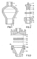
- the pre-column shown in the longitudinal sectional view of Figure 1 consists of one assembly and is made of stainless steel.
- the cylindrical central part 1 converges conically towards the two ends, the part 2 converging more strongly in the direction of the upstream end 3 than the part 4 in the direction of the downstream end 5.
- the upstream end 3 has internal screwthread into which a nipple having external screwthread can be screwed.
- An inlet tube for the liquid to be chromatographed can be connected to said nipple.
- the downstream end has external screwthread with which the pre-column can be screwed into a coupling member, as shown for example in Figure 6, and has a projecting circumferential edge or ridge 6 which forms a mount for a gasket.
- FIGs 2 and 3 are cross-sectional views of pre-columns according to the invention which are composed of two parts, namely vessels 70 and 54, respectively, and covers 48 and 55, respectively.
- the cover of the pre-column shown in Figure 2 has a nipple 71 to which an inlet tube can be connected through which liquid can reach the interior of the column via central bore 72.
- the cover has external screwthread 73 with which it can be screwed into the vessel having internal screwthread 74 up to a gasket 75 which fits in a mount 76 of the vessel.
- the gasket 75 in which a filter of sintered metal 50 is mounted, is shown on an enlarged scale in the drawing.
- the vessel 70 at the downstream end has an external circumferential ridge 77 which forms a mount for a gasket, and has screwthread 78 with which the column can be screwed into a coupling member, for example, as shown in Figures 7 and 8.
- the column tapers conically towards the two ends, towards the upstream end at an angle of 75°, towards the downstream end at an angle of 27°.
- the vessel at the downstream end again has externally a circumferential ridge 87 and screwthread 88.
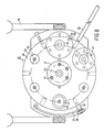
- Figure 4 is a plan view of a coupling member of a device for a liquid chromatography system to which a pre-column can be connected at 96.
- the coupling member comprises two concentric disks 7 and 8, also of stainless steel, disk 7 being rotatable about a bearing boss 9. The disks are clamped one on the other by the same boss 9 which is constructed as a bolt and is screwed through disk 7.
- Circular gaskets (for example, 10 and 11) of teflon which have an approximately circular cross-section are present between the two disks in grooves recessed in one of the disks.
- the circular gaskets are present between the disks and are provided around the bores (see hereinafter) in the disks.
- the connection aperture for the pre-column 96 has external screwthread so that the column can be screwed into it up to a sealing gasket 12 of reinforced teflon.
- the aperture 96 is narrowed to form a bore having a smaller diameter, while a filter of sintered metal 90 which is disk-shaped is present between the connection aperture and the bore.
- a handle 13 is provided on the outer edge of the same disk in which the connection aperture for the pre-column is recessed.
- Said disk furthermore comprises a nipple 14 for the connection to an inlet tube for conditioning liquid.
- a conditioning liquid is used to condition the separating column or columns prior to the chromatography process.
- a handle 15 is connected by means of two bolts, which handle can be fixed at its end 16 remote from the disk in a stand.
- An insert 18 for the connection to a separating column and having a central bore is present in a mount 17 of the same disk.
- This latter disk moreover comprises a nipple 19 for the connection to an outlet tube for waste liquid.
- The- disk furthermore comprises an abutment plate and pin 20, 21, as a result of which the rotational distance of the disks relative to each other necessary to make the apertures in the disks communicate with each other can more easily be determined.
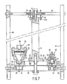
- the device shown in Figures 7 and 8 for a liquid chromatography system comprises a coupling member 22 consisting of two concentric stainless steel disks which are rotatable about a shaft 23 which has bearings at each end and in which disks apertures are recessed.
- the same teflon gaskets are present as described before the Figures 4-6 embodiment.
- the upper disk 24 is connected to a flange 26 of the central shaft 23 by means of bolts 25.
- the upper disk is rotatable relative to the lower disk, the shaft also rotating.
- Six apertures are recessed in the upper disk and are provided with screwthread so that either pre-columns (at 29,30 and 31) or, as at 32, inserts .
- the upper disk can be rotated with respect to the lower disk by means of a handle 36.
- the lower disk 28 furthermore comprises a locking device for the upper disk 24, comprising a resilient arm 37 having a pawl 61 which falls into apertures recessed in the outer edge of the upper disk.
- the lower disk At its outer edge the lower disk is screwed into a stand 39, comprising two diametrically oppositely located rod-shaped elements 40 extending parallel to the central shaft 23.
- two circular stainless steel plates 41, 42 are connected to the central shaft 23, the uppermost 41 of which being connected to the rod-shaped elements 40 of the stand by means of connection bars or spokes 43.
- the plates are sealingly clamped one on top of the other, circular teflon gaskets being provided between the plates as was the case with the disks of the coupling member.
- the lower plate 42 is rigidly secured to the bearing shaft 23 by means of bolts'44, and hence rotates with the upper disk 24 of the coupling member 23.
- Both plates 41 and 42 comprise nipples 27, 27a which are connected to bores provided in the plates.
- the nipples in the lower plate 42 can be connected by means of liquid tubes to the nipples or pre-columns in the upper disk 24 of the coupling member 22; the nipples in the upper plate 41 can be connected to reservoirs containing different liquids, for example, conditioning liquid, liquid to be chromatographed and various elution liquids.
- the device shown in Figures 7 and 8 is excellently suitable for an automatic chromatography process, because between conditioning, loading the pre-column or columns with trace components to be separated, and various elutions, no inlet tubes need be detached. Any desired liquid can be introduced into one of the pre-columns or separating columns by a simple rotation of the upper coupling disk.
- the column is sealingly connected to the elongated bore 62 of the aperture 29 recessed in the upper coupling disk 24 by means of a teflon gasket 53.
- Column 46 consists of two parts (54 and 55) which are connected together by means of bolts 56.
- filters of sintered metal 57, 58 are also present in column 46, while the sealing to the upper coupling disk 24 is formed by a teflon gasket 59.
- the column communicates at the downstream end with aperture 63 in disk 24.
- the carrier material for example a hydrophobated silica gel, for example Corasil, Nucleosil, Zorbax or Lichroprep (reg. trade marks) is enclosed between two filters of sintered metal in the column.
- An inert filler in this case glass beads, is provided on the filter in the conical part on the side of the upstream end of the column.
- the pre-column is connected to the coupling device shown in Figures 5-6 or in Figures 7-8. In the device shown in Figures 7-8 more pre-columns are used according to the invention.
- the device further comprises one or more separating columns which are preferably filled with the same type of carrier material.
- conditioning liquid is rinsed through the columns and collected in a waste vessel.
- the pre-column is then loaded with the material to be chromatographed for example, a urine sample, by causing this material to flow through the pre-column which is connected to an outlet tube.
- the pre-column is connected to a separating column, after which the column is eluted.
- a so-called gradient elution is preferably used, which means that during the elution process the composition of the eluent is varied.
- the elution rate i.e.
- the rate at which the eluent is pumped through the columns depends on the dimensions of pre-column(s) and separating column(s), on the material to be chromatographed, the carrier material and the elution liquid.
- the elution is preferably carried out at room temperature; during the elution the pressure in the columns and coupling device may increase to 20 to 30 MPa, even to 40 MPa.
- the detection of the trace components may take place in various manners, for example, by means of spectroscopic methods such as UV-spectroscopy. In most of the cases, however, too many chromo- phorous "impurities" are present in the eluate to be able to successfully use a UV-measurement.
- a radioactivity-measurement is used.
- the chemical compound to be examined usually a medicament
- radioactive labelled carbon or hydrogen: 14C or 3 H By measuring the emitted radioactivity, both the chemical compound itself and also possible metabolites thereof which comprise the labelled fragment, can be detected. This detection may take place “on-line” in the eluate flow, or "off-line", i.e. in the collected eluate fractions.
- the former method is more rapid, the "off-line" detection method usually gives more accurate results.
- Isoxsuprine and metabolites hereof in urine 200 ml of urine were subjected to the above-described chromatography process.
- Isoxsuprine or p - hydroxy - a - [1 - ⁇ (1 - methyl - 2 - phenoxyethyl)amino ⁇ - ethyl]benzylalcohol is a substance having a vasodilating activity.
- the medicament and the metabolites hereof were present in traces in the sample to be chromatographed, namely in an overall quantity of a few micrograms.
- a stainless steel column according to the invention was used of the type as shown in Figure 3 having a capacity of 27 ml.
- Nucleosil (reg. trade mark) 30 C 8 a hydrophobated silica gel.
- the separating column had an inside diameter of 9 mm and a length of 50 cm, and was filled with Zorbax (reg. trade mark) 7 C 8, also a hydrophobated silica gel.
- Isoxsuprine was labelled with 3 H.
- the gradient elution was carried out with a mixture of water and methanol having a methanol content increasing from 0 to 100%. The elution rate was approximately 5 ml per minute.
- the trace components were detected off-line the chromatogram shown in Figure 9 being obtained.
- the measured radioactivity RA in counts per minute is plotted against time in minutes.
- the peak denoted in the chromatogram by I is of Isoxsuprine, the other peaks represent metabolites of Isoxsuprine.
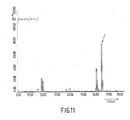
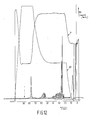
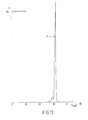
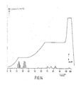
- the pre-column according to the invention was also used in solving various other separating problems, as appears from the chromatograms shown in Figures 11, 12, 13 and 14.
- Figure 11 stainless steel pre-column as shown in Figure 2; capacity 1.5 ml; filler Nucleosil (reg. trade mark) 30 C 8. Separating column: stainless steel; length 500 mm; inside diameter 9 mm; filler Nucleosil (reg. trade mark) 7 C 8. Provided sample: 22 ml of blood plasma of a dog. Elution: gradient elution with a mixture of water and methanol having a methanol content increasing from 0 to 100%. The compound was labelled with 14 C. Detection: off-line; measured radioactivity RA in counts per minute. The peak at T is of the active compound: the other ones are of metabolites.
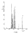
- Figure 12 stainless steel pre-column as shown in Figure 3; capacity 27 ml; filler Nucleosil (reg. trade mark) 7 C 8. Separating column: stainless steel; length 500 mm; inside diameter 9 mm; filler Nucleosil (reg. trade mark) 7 C 8.
- sample 620 ml of urine of a dog.
- Elution gradient elution with a mixture of water and methanol having a methanol content increasing from 0 to 100%.
- the compound was labelled with 14C: Detection: on-line.
- the peak at T is of the active compound; the other ones are of metabolites.
- the gradient profile of the eluent in % methanol is denoted by GP.
- the pressure within the system is denoted by p. This pressure reaches a maximum value of approx. 5400 psi, i.e. approx 35 MPa.
- Figure 13 shows a chromatogram obtained by chromatography of a urine sample to which 0.5 ppb of DES had been added.
- DES or diethylstil- bestrol is a substance having oestrogenic activity.
- Stainless steel pre-column according to the invention having a capacity of 13 ml; filler Lichroprop (reg. trade mark) RP2, a hydrophobated silica gel. Separating column: stainless steel; length 250 mm; inside diameter 9 mm; filler Nucleosil (reg. trade mark) 7 C 8.
- Elution gradient elution with water-methanol having a methanol content increasing from 0 to 100%.
- DES was labelled with 3 H. Detection: off-line. The peak at D is of DES.
- the chromatogram of Figure 14 has been obtained by column chromatography of a urine sample of a rat containing traces of N - (2,6 - difluorobenzoyl) - N' - (4 - trifluoromethylphenyl) urea and metabolites hereof; this urea compound can be used as an insecticide in agriculture, horticulture and forestry.
- Separating column stainless steel; length 500 mm, inside diameter 9 mm; filler Zorbax (reg. trade mark) 7 C 8.
- Elution gradient elution with a mixture of water and methanol having a methanol content increasing from 0 to 100%.
- the compound was labelled with 14C. Detection: on-line.
- the peak at P is of the active compound, the other ones are of metabolites.
- the gradient profile of the eluent in % methanol is denoted by GP.
Landscapes
- Chemical & Material Sciences (AREA)
- Analytical Chemistry (AREA)
- General Health & Medical Sciences (AREA)
- Life Sciences & Earth Sciences (AREA)
- Health & Medical Sciences (AREA)
- Biochemistry (AREA)
- Physics & Mathematics (AREA)
- General Physics & Mathematics (AREA)
- Immunology (AREA)
- Pathology (AREA)
- Chemical Kinetics & Catalysis (AREA)
- Treatment Of Liquids With Adsorbents In General (AREA)
- Organic Low-Molecular-Weight Compounds And Preparation Thereof (AREA)
Claims (7)
Priority Applications (1)
| Application Number | Priority Date | Filing Date | Title |
|---|---|---|---|
| AT83200476T ATE20829T1 (de) | 1982-04-28 | 1983-04-01 | Vorsaeule zum vorkonzentrieren von durch chromatographie zu trennenden stoffen, sowie vorrichtung fuer ein fluessigkeitschromatographiesystem und kupplungsstueck fuer diese vorrichtung. |
Applications Claiming Priority (2)
| Application Number | Priority Date | Filing Date | Title |
|---|---|---|---|
| NL8201757 | 1982-04-28 | ||
| NL8201757 | 1982-04-28 |
Publications (2)
| Publication Number | Publication Date |
|---|---|
| EP0092860A1 EP0092860A1 (fr) | 1983-11-02 |
| EP0092860B1 true EP0092860B1 (fr) | 1986-07-23 |
Family
ID=19839666
Family Applications (1)
| Application Number | Title | Priority Date | Filing Date |
|---|---|---|---|
| EP83200476A Expired EP0092860B1 (fr) | 1982-04-28 | 1983-04-01 | Précolonne pour préconcentrer des substances à séparer par chromatographie, ainsi que dispositif pour un système de chromatographie liquide et un organe de couplage pour ce dispositif |
Country Status (12)
| Country | Link |
|---|---|
| US (1) | US4554071A (fr) |
| EP (1) | EP0092860B1 (fr) |
| JP (1) | JPS58196455A (fr) |
| KR (1) | KR900008957B1 (fr) |
| AT (1) | ATE20829T1 (fr) |
| AU (1) | AU558353B2 (fr) |
| CA (2) | CA1203224A (fr) |
| DE (1) | DE3364639D1 (fr) |
| DK (1) | DK163801C (fr) |
| ES (2) | ES279037Y (fr) |
| IL (1) | IL68480A0 (fr) |
| ZA (1) | ZA832902B (fr) |
Families Citing this family (39)
| Publication number | Priority date | Publication date | Assignee | Title |
|---|---|---|---|---|
| US4719011A (en) * | 1985-03-22 | 1988-01-12 | H. T. Chemicals, Inc. | High pressure liquid chromatography columns |
| DE3606474A1 (de) * | 1986-02-28 | 1987-09-17 | Merck Patent Gmbh | Chromatographievorsaeule |
| JPS6332368A (ja) * | 1986-07-25 | 1988-02-12 | Tosoh Corp | 高密度充填型の濾過装置 |
| JP2766869B2 (ja) * | 1988-03-09 | 1998-06-18 | 扶桑薬品工業株式会社 | 体液材料中の低級カルボン酸の定量法 |
| JP2625001B2 (ja) * | 1988-06-23 | 1997-06-25 | 明文 山田 | 塩化物イオン置換カラム及びこれを用いたフローインジェクション分析装置 |
| DE3842315A1 (de) * | 1988-12-16 | 1990-06-21 | Bodenseewerk Perkin Elmer Co | Anordnung zur anreicherung von probensubstanz fuer spektroskopische zwecke |
| US5246577A (en) * | 1990-05-29 | 1993-09-21 | Millipore Corporation | Apparatus for effecting capillary electrophoresis |
| DE4110730A1 (de) * | 1991-04-03 | 1992-10-15 | Fresenius Ag | Vorrichtung zur auftrennung von zumindest zwei biologischen stoffen in loesung durch adsorption |
| US5338448A (en) * | 1992-10-16 | 1994-08-16 | Sarasep, Inc. | Method of preventing contamination of a chromatography column |
| JPH07198701A (ja) * | 1993-11-26 | 1995-08-01 | Ngk Insulators Ltd | 低圧高速液体クロマトグラフィー用カラム、低圧高速液体クロマトグラフィー用カラム装置及び同カラム装置の使用方法 |
| US5462660A (en) * | 1994-04-22 | 1995-10-31 | The United States Of America As Represented By The Secretary Of Agriculture | High performance liquid chromatography injection system for the simultaneous concentration and analysis of trace components |
| EP0686848A1 (fr) * | 1994-05-09 | 1995-12-13 | Shiseido Company Limited | Chromatograph en phase liquide ayant une colonne micro ou semi-micro |
| ES2103224B1 (es) * | 1994-05-18 | 1998-04-16 | Univ Cordoba | Analizador automatico para el tratamiento previo de muestras liquidas. |
| US6177008B1 (en) * | 1996-08-01 | 2001-01-23 | Merck & Co., Inc. | Dual compartment solid phase extraction cartridge |
| EP1033572A4 (fr) * | 1998-09-18 | 2001-02-07 | Eisai Co Ltd | Colonne pour concentrer un composant dans un echantillon |
| US6458273B1 (en) | 1999-10-29 | 2002-10-01 | Ontogen Corporation | Sample separation apparatus and method for multiple channel high throughput purification |
| US6309541B1 (en) | 1999-10-29 | 2001-10-30 | Ontogen Corporation | Apparatus and method for multiple channel high throughput purification |
| US20020008058A1 (en) * | 1999-06-03 | 2002-01-24 | Kerry D. Nugent | Tapered bore column for high performance liquid chromatography |
| US6358414B1 (en) | 1999-10-29 | 2002-03-19 | Ontogen Corporation | Pressure regulation apparatus and method for multiple channel high throughput purification |
| US6355164B1 (en) | 1999-10-29 | 2002-03-12 | Ontogen Corporation | Sample collection apparatus and method for multiple channel high throughput purification |
| US6723236B2 (en) * | 2002-03-19 | 2004-04-20 | Waters Investments Limited | Device for solid phase extraction and method for purifying samples prior to analysis |
| JP2006153850A (ja) * | 2004-08-31 | 2006-06-15 | Showa Denko Kk | 化合物精製濃縮用具及びそれを用いた化合物の精製濃縮方法 |
| DE102006028126A1 (de) * | 2006-06-15 | 2007-12-20 | Sls Micro Technology Gmbh | Miniaturisierte gaschromatographische Analysevorrichtung mit Probenanreicherung |
| US9005417B1 (en) * | 2008-10-01 | 2015-04-14 | Sandia Corporation | Devices, systems, and methods for microscale isoelectric fractionation |
| US8962346B2 (en) | 2010-07-08 | 2015-02-24 | Sandia Corporation | Devices, systems, and methods for conducting assays with improved sensitivity using sedimentation |
| US9795961B1 (en) | 2010-07-08 | 2017-10-24 | National Technology & Engineering Solutions Of Sandia, Llc | Devices, systems, and methods for detecting nucleic acids using sedimentation |
| US8945914B1 (en) | 2010-07-08 | 2015-02-03 | Sandia Corporation | Devices, systems, and methods for conducting sandwich assays using sedimentation |
| US9261100B2 (en) | 2010-08-13 | 2016-02-16 | Sandia Corporation | Axial flow heat exchanger devices and methods for heat transfer using axial flow devices |
| ES2572914T3 (es) * | 2011-06-03 | 2016-06-03 | Dow Global Technologies Llc | Cromatografía de polímeros |
| US9244065B1 (en) | 2012-03-16 | 2016-01-26 | Sandia Corporation | Systems, devices, and methods for agglutination assays using sedimentation |
| US9803238B1 (en) | 2013-11-26 | 2017-10-31 | National Technology & Engineering Solutions Of Sandia, Llc | Method and apparatus for purifying nucleic acids and performing polymerase chain reaction assays using an immiscible fluid |
| US9702871B1 (en) | 2014-11-18 | 2017-07-11 | National Technology & Engineering Solutions Of Sandia, Llc | System and method for detecting components of a mixture including a valving scheme for competition assays |
| US10254298B1 (en) | 2015-03-25 | 2019-04-09 | National Technology & Engineering Solutions Of Sandia, Llc | Detection of metabolites for controlled substances |
| US9804133B1 (en) * | 2015-08-27 | 2017-10-31 | Mark A. Stone | Method to enable the use of larger injection volumes and to reduce extra-column effects in chromatographic separations |
| US10786755B2 (en) * | 2015-08-27 | 2020-09-29 | Mark A. Stone | Low-retention pre-columns: a straightforward approach to enable larger injection volumes and reduce extra-column effects in HPLC |
| US10981174B1 (en) | 2016-08-04 | 2021-04-20 | National Technology & Engineering Solutions Of Sandia, Llc | Protein and nucleic acid detection for microfluidic devices |
| US10406528B1 (en) | 2016-08-04 | 2019-09-10 | National Technology & Engineering Solutions Of Sandia, Llc | Non-contact temperature control system for microfluidic devices |
| US10786811B1 (en) | 2016-10-24 | 2020-09-29 | National Technology & Engineering Solutions Of Sandia, Llc | Detection of active and latent infections with microfluidic devices and systems thereof |
| US11305272B2 (en) * | 2016-12-13 | 2022-04-19 | Organo Corporation | Ion exchanger filled cartridge and metal removing column |
Family Cites Families (10)
| Publication number | Priority date | Publication date | Assignee | Title |
|---|---|---|---|---|
| US3220164A (en) * | 1962-07-18 | 1965-11-30 | Perkin Elmer Corp | Recirculation chromatography |
| US3578785A (en) * | 1968-02-12 | 1971-05-18 | Sondell Research & Dev Co | Outlet plug and conduit for chromatograph |
| US3782078A (en) * | 1972-02-14 | 1974-01-01 | J Jerpe | Apparatus for chromatographic separations |
| JPS508593A (fr) * | 1973-05-21 | 1975-01-29 | ||
| US4070284A (en) * | 1973-08-20 | 1978-01-24 | Hitachi, Ltd. | Liquid chromatography and apparatus for the same |
| JPS5233595A (en) * | 1975-09-09 | 1977-03-14 | Kusano Kagaku Kikai Seisakusho:Kk | Pressure resistant column for liquid column chromatography |
| JPS5338958A (en) * | 1976-09-22 | 1978-04-10 | Nippon Gakki Seizo Kk | Monostable multi-vibrator circuit |
| US4250035A (en) * | 1978-11-13 | 1981-02-10 | Waters Associates, Inc. | Radial compression of packed beds |
| JPS5570738A (en) * | 1978-11-22 | 1980-05-28 | Kusano Kagaku Kikai Seisakusho:Kk | High pressure glass column for high speed liquid chromatograph |
| FR2491215A1 (fr) * | 1980-09-26 | 1982-04-02 | Prolabo Sa | Dispositif pour associer une precolonne et une colonne en chromatographie, emploi dudit dispositif pour la realisation d'un chromatographe automatique industriel |
-
1983
- 1983-04-01 DE DE8383200476T patent/DE3364639D1/de not_active Expired
- 1983-04-01 AT AT83200476T patent/ATE20829T1/de not_active IP Right Cessation
- 1983-04-01 EP EP83200476A patent/EP0092860B1/fr not_active Expired
- 1983-04-22 AU AU13889/83A patent/AU558353B2/en not_active Ceased
- 1983-04-25 IL IL68480A patent/IL68480A0/xx not_active IP Right Cessation
- 1983-04-25 KR KR1019830001744A patent/KR900008957B1/ko not_active IP Right Cessation
- 1983-04-25 ES ES1983279037U patent/ES279037Y/es not_active Expired
- 1983-04-25 DK DK182383A patent/DK163801C/da not_active IP Right Cessation
- 1983-04-25 ZA ZA832902A patent/ZA832902B/xx unknown
- 1983-04-25 ES ES521816A patent/ES521816A0/es active Granted
- 1983-04-26 CA CA000426761A patent/CA1203224A/fr not_active Expired
- 1983-04-26 CA CA000426760A patent/CA1205751A/fr not_active Expired
- 1983-04-28 JP JP58074233A patent/JPS58196455A/ja active Granted
-
1984
- 1984-09-07 US US06/648,358 patent/US4554071A/en not_active Expired - Lifetime
Also Published As
| Publication number | Publication date |
|---|---|
| CA1205751A (fr) | 1986-06-10 |
| AU558353B2 (en) | 1987-01-29 |
| JPH0546499B2 (fr) | 1993-07-14 |
| DK163801C (da) | 1992-09-07 |
| JPS58196455A (ja) | 1983-11-15 |
| ES279037U (es) | 1984-12-01 |
| ZA832902B (en) | 1984-01-25 |
| KR840004577A (ko) | 1984-10-22 |
| ES279037Y (es) | 1985-06-01 |
| EP0092860A1 (fr) | 1983-11-02 |
| DK182383A (da) | 1983-10-29 |
| US4554071A (en) | 1985-11-19 |
| DK163801B (da) | 1992-04-06 |
| ES8402165A1 (es) | 1984-01-16 |
| CA1203224A (fr) | 1986-04-15 |
| KR900008957B1 (ko) | 1990-12-15 |
| ES521816A0 (es) | 1984-01-16 |
| DK182383D0 (da) | 1983-04-25 |
| DE3364639D1 (en) | 1986-08-28 |
| IL68480A0 (en) | 1983-07-31 |
| ATE20829T1 (de) | 1986-08-15 |
| AU1388983A (en) | 1983-11-03 |
Similar Documents
| Publication | Publication Date | Title |
|---|---|---|
| EP0092860B1 (fr) | Précolonne pour préconcentrer des substances à séparer par chromatographie, ainsi que dispositif pour un système de chromatographie liquide et un organe de couplage pour ce dispositif | |
| Roth et al. | Fully automated high-performance liquid chromatography: A new chromatograph for pharmacokinetic drug monitoring by direct injection of body fluids | |
| US20180356375A1 (en) | Chromatography columns, systems and methods | |
| Scott et al. | Use of microbore columns for the separation of substances of biological origin | |
| US5651885A (en) | Column for liquid chromatography | |
| US5482628A (en) | Column for liquid chromatography | |
| EP1485179B1 (fr) | Dispositif d'extraction en phase solide et procédé de séparation | |
| US4131544A (en) | Macroencapsulated sorbent element and process for using the same | |
| Jentoft et al. | Apparatus for supercritical fluid chromatography with carbon dioxide as the mobile phase | |
| US5472598A (en) | Connection assembly for liquid chromatography columns | |
| US3847550A (en) | Differential chromatographic method | |
| US4476017A (en) | Removable synthesis column | |
| AU1399899A (en) | Liquid chromatography column | |
| Valcárcel et al. | Coupling continuous separation techniques to capillary electrophoresis | |
| US5472612A (en) | Supercritical fluid extraction system and method of operation | |
| JPH02262054A (ja) | 高速液体クロマトグラフ用フィルター | |
| Cappiello et al. | New materials and packing techniques for micro-HPLC packed capillary columns | |
| Fritz et al. | Chromatographic separation of phenols using an acrylic resin | |
| Juergens | HPLC analysis of antiepileptic drugs in blood samples: microbore separation of fourteen compounds | |
| KR940002497B1 (ko) | 카본블랙의 비(非)공극 표면적 측정방법 및 장치 | |
| Jay | Anion contamination of environmental water samples introduced by filter media | |
| EP0944420B1 (fr) | Colonne de chromatographie liquide | |
| Oka et al. | On-line extraction, evaporation, and injection for liquid chromatographic determination of serum corticosteroids | |
| Alvarez et al. | Thin-layer chromatographic collector-eluter | |
| Eckers et al. | Practical microbore column HPLC: System development and drug applications |
Legal Events
| Date | Code | Title | Description |
|---|---|---|---|
| PUAI | Public reference made under article 153(3) epc to a published international application that has entered the european phase |
Free format text: ORIGINAL CODE: 0009012 |
|
| AK | Designated contracting states |
Designated state(s): AT BE CH DE FR GB IT LI LU NL SE |
|
| 17P | Request for examination filed |
Effective date: 19840404 |
|
| GRAA | (expected) grant |
Free format text: ORIGINAL CODE: 0009210 |
|
| AK | Designated contracting states |
Kind code of ref document: B1 Designated state(s): AT BE CH DE FR GB IT LI LU NL SE |
|
| REF | Corresponds to: |
Ref document number: 20829 Country of ref document: AT Date of ref document: 19860815 Kind code of ref document: T |
|
| ITF | It: translation for a ep patent filed |
Owner name: ING. C. GREGORJ S.P.A. |
|
| REF | Corresponds to: |
Ref document number: 3364639 Country of ref document: DE Date of ref document: 19860828 |
|
| ET | Fr: translation filed | ||
| PLBE | No opposition filed within time limit |
Free format text: ORIGINAL CODE: 0009261 |
|
| STAA | Information on the status of an ep patent application or granted ep patent |
Free format text: STATUS: NO OPPOSITION FILED WITHIN TIME LIMIT |
|
| 26N | No opposition filed | ||
| ITTA | It: last paid annual fee | ||
| PGFP | Annual fee paid to national office [announced via postgrant information from national office to epo] |
Ref country code: LU Payment date: 19930407 Year of fee payment: 11 |
|
| PGFP | Annual fee paid to national office [announced via postgrant information from national office to epo] |
Ref country code: AT Payment date: 19930428 Year of fee payment: 11 |
|
| EPTA | Lu: last paid annual fee | ||
| PG25 | Lapsed in a contracting state [announced via postgrant information from national office to epo] |
Ref country code: LU Free format text: LAPSE BECAUSE OF NON-PAYMENT OF DUE FEES Effective date: 19940401 Ref country code: AT Effective date: 19940401 |
|
| EAL | Se: european patent in force in sweden |
Ref document number: 83200476.6 |
|
| REG | Reference to a national code |
Ref country code: CH Ref legal event code: PUE Owner name: HENRI MARIE RUIJTEN |
|
| REG | Reference to a national code |
Ref country code: GB Ref legal event code: 732E |
|
| REG | Reference to a national code |
Ref country code: FR Ref legal event code: TP |
|
| NLS | Nl: assignments of ep-patents |
Owner name: H.M. RUIJTEN TE BUSSUM. |
|
| PGFP | Annual fee paid to national office [announced via postgrant information from national office to epo] |
Ref country code: NL Payment date: 19990429 Year of fee payment: 17 |
|
| PGFP | Annual fee paid to national office [announced via postgrant information from national office to epo] |
Ref country code: FR Payment date: 20000317 Year of fee payment: 18 |
|
| PGFP | Annual fee paid to national office [announced via postgrant information from national office to epo] |
Ref country code: SE Payment date: 20000320 Year of fee payment: 18 Ref country code: DE Payment date: 20000320 Year of fee payment: 18 |
|
| PGFP | Annual fee paid to national office [announced via postgrant information from national office to epo] |
Ref country code: GB Payment date: 20000321 Year of fee payment: 18 |
|
| PGFP | Annual fee paid to national office [announced via postgrant information from national office to epo] |
Ref country code: CH Payment date: 20000322 Year of fee payment: 18 |
|
| PGFP | Annual fee paid to national office [announced via postgrant information from national office to epo] |
Ref country code: BE Payment date: 20000329 Year of fee payment: 18 |
|
| PG25 | Lapsed in a contracting state [announced via postgrant information from national office to epo] |
Ref country code: NL Free format text: LAPSE BECAUSE OF NON-PAYMENT OF DUE FEES Effective date: 20001101 |
|
| NLV4 | Nl: lapsed or anulled due to non-payment of the annual fee |
Effective date: 20001101 |
|
| PG25 | Lapsed in a contracting state [announced via postgrant information from national office to epo] |
Ref country code: GB Free format text: LAPSE BECAUSE OF NON-PAYMENT OF DUE FEES Effective date: 20010401 |
|
| PG25 | Lapsed in a contracting state [announced via postgrant information from national office to epo] |
Ref country code: SE Free format text: LAPSE BECAUSE OF NON-PAYMENT OF DUE FEES Effective date: 20010402 |
|
| PG25 | Lapsed in a contracting state [announced via postgrant information from national office to epo] |
Ref country code: CH Free format text: LAPSE BECAUSE OF NON-PAYMENT OF DUE FEES Effective date: 20010430 Ref country code: FR Free format text: THE PATENT HAS BEEN ANNULLED BY A DECISION OF A NATIONAL AUTHORITY Effective date: 20010430 Ref country code: LI Free format text: LAPSE BECAUSE OF NON-PAYMENT OF DUE FEES Effective date: 20010430 Ref country code: BE Free format text: LAPSE BECAUSE OF NON-PAYMENT OF DUE FEES Effective date: 20010430 |
|
| BERE | Be: lapsed |
Owner name: RUIJTEN HENRI MARIE Effective date: 20010430 |
|
| GBPC | Gb: european patent ceased through non-payment of renewal fee |
Effective date: 20010401 |
|
| EUG | Se: european patent has lapsed |
Ref document number: 83200476.6 |
|
| REG | Reference to a national code |
Ref country code: CH Ref legal event code: PL |
|
| PG25 | Lapsed in a contracting state [announced via postgrant information from national office to epo] |
Ref country code: DE Free format text: LAPSE BECAUSE OF NON-PAYMENT OF DUE FEES Effective date: 20020201 |
|
| REG | Reference to a national code |
Ref country code: FR Ref legal event code: ST |