EP0092853A2 - Verfahren zur Herstellung eines vorgefertigten Gebäudes - Google Patents
Verfahren zur Herstellung eines vorgefertigten Gebäudes Download PDFInfo
- Publication number
- EP0092853A2 EP0092853A2 EP83104757A EP83104757A EP0092853A2 EP 0092853 A2 EP0092853 A2 EP 0092853A2 EP 83104757 A EP83104757 A EP 83104757A EP 83104757 A EP83104757 A EP 83104757A EP 0092853 A2 EP0092853 A2 EP 0092853A2
- Authority
- EP
- European Patent Office
- Prior art keywords
- insulation
- blanket
- assembly
- panels
- structural assembly
- Prior art date
- Legal status (The legal status is an assumption and is not a legal conclusion. Google has not performed a legal analysis and makes no representation as to the accuracy of the status listed.)
- Withdrawn
Links
- 238000000034 method Methods 0.000 title claims abstract description 11
- 230000004888 barrier function Effects 0.000 claims abstract description 5
- 238000009413 insulation Methods 0.000 claims description 70
- 239000012774 insulation material Substances 0.000 claims description 6
- 239000000758 substrate Substances 0.000 claims description 3
- 239000000463 material Substances 0.000 claims description 2
- 230000000712 assembly Effects 0.000 description 10
- 238000000429 assembly Methods 0.000 description 10
- 238000009434 installation Methods 0.000 description 4
- 230000007797 corrosion Effects 0.000 description 3
- 238000005260 corrosion Methods 0.000 description 3
- 230000035515 penetration Effects 0.000 description 3
- 239000007787 solid Substances 0.000 description 3
- XLYOFNOQVPJJNP-UHFFFAOYSA-N water Substances O XLYOFNOQVPJJNP-UHFFFAOYSA-N 0.000 description 3
- 230000006835 compression Effects 0.000 description 2
- 238000007906 compression Methods 0.000 description 2
- 230000008602 contraction Effects 0.000 description 2
- 230000000284 resting effect Effects 0.000 description 2
- 239000007779 soft material Substances 0.000 description 2
- 101100084165 Caenorhabditis elegans prdx-2 gene Proteins 0.000 description 1
- 230000003466 anti-cipated effect Effects 0.000 description 1
- 230000009286 beneficial effect Effects 0.000 description 1
- 238000002788 crimping Methods 0.000 description 1
- 230000006866 deterioration Effects 0.000 description 1
- 230000001627 detrimental effect Effects 0.000 description 1
- 238000005553 drilling Methods 0.000 description 1
- 230000000694 effects Effects 0.000 description 1
- 239000013013 elastic material Substances 0.000 description 1
- 239000000835 fiber Substances 0.000 description 1
- 239000011152 fibreglass Substances 0.000 description 1
- 239000003365 glass fiber Substances 0.000 description 1
- 229910052500 inorganic mineral Inorganic materials 0.000 description 1
- 230000014759 maintenance of location Effects 0.000 description 1
- 238000002844 melting Methods 0.000 description 1
- 230000008018 melting Effects 0.000 description 1
- 239000011707 mineral Substances 0.000 description 1
- 238000003825 pressing Methods 0.000 description 1
- 238000010079 rubber tapping Methods 0.000 description 1
- 239000000565 sealant Substances 0.000 description 1
- 125000006850 spacer group Chemical group 0.000 description 1
- 230000000007 visual effect Effects 0.000 description 1
- 239000011800 void material Substances 0.000 description 1
Images

Classifications
-
- E—FIXED CONSTRUCTIONS
- E04—BUILDING
- E04D—ROOF COVERINGS; SKY-LIGHTS; GUTTERS; ROOF-WORKING TOOLS
- E04D3/00—Roof covering by making use of flat or curved slabs or stiff sheets
- E04D3/36—Connecting; Fastening
- E04D3/3601—Connecting; Fastening of roof covering supported by the roof structure with interposition of a insulating layer
- E04D3/3602—The fastening means comprising elongated profiles installed in or on the insulation layer
-
- E—FIXED CONSTRUCTIONS
- E04—BUILDING
- E04C—STRUCTURAL ELEMENTS; BUILDING MATERIALS
- E04C3/00—Structural elongated elements designed for load-supporting
- E04C3/02—Joists; Girders, trusses, or trusslike structures, e.g. prefabricated; Lintels; Transoms; Braces
- E04C3/04—Joists; Girders, trusses, or trusslike structures, e.g. prefabricated; Lintels; Transoms; Braces of metal
- E04C3/08—Joists; Girders, trusses, or trusslike structures, e.g. prefabricated; Lintels; Transoms; Braces of metal with apertured web, e.g. with a web consisting of bar-like components; Honeycomb girders
-
- E—FIXED CONSTRUCTIONS
- E04—BUILDING
- E04D—ROOF COVERINGS; SKY-LIGHTS; GUTTERS; ROOF-WORKING TOOLS
- E04D13/00—Special arrangements or devices in connection with roof coverings; Protection against birds; Roof drainage ; Sky-lights
- E04D13/16—Insulating devices or arrangements in so far as the roof covering is concerned, e.g. characterised by the material or composition of the roof insulating material or its integration in the roof structure
- E04D13/1606—Insulation of the roof covering characterised by its integration in the roof structure
- E04D13/1612—Insulation of the roof covering characterised by its integration in the roof structure the roof structure comprising a supporting framework of roof purlins or rafters
- E04D13/1618—Insulation of the roof covering characterised by its integration in the roof structure the roof structure comprising a supporting framework of roof purlins or rafters with means for fixing the insulating material between the roof covering and the upper surface of the roof purlins or rafters
-
- E—FIXED CONSTRUCTIONS
- E04—BUILDING
- E04D—ROOF COVERINGS; SKY-LIGHTS; GUTTERS; ROOF-WORKING TOOLS
- E04D3/00—Roof covering by making use of flat or curved slabs or stiff sheets
- E04D3/36—Connecting; Fastening
- E04D3/3607—Connecting; Fastening the fastening means comprising spacer means adapted to the shape of the profiled roof covering
-
- E—FIXED CONSTRUCTIONS
- E04—BUILDING
- E04D—ROOF COVERINGS; SKY-LIGHTS; GUTTERS; ROOF-WORKING TOOLS
- E04D3/00—Roof covering by making use of flat or curved slabs or stiff sheets
- E04D3/36—Connecting; Fastening
- E04D3/3608—Connecting; Fastening for double roof covering or overroofing
-
- F—MECHANICAL ENGINEERING; LIGHTING; HEATING; WEAPONS; BLASTING
- F16—ENGINEERING ELEMENTS AND UNITS; GENERAL MEASURES FOR PRODUCING AND MAINTAINING EFFECTIVE FUNCTIONING OF MACHINES OR INSTALLATIONS; THERMAL INSULATION IN GENERAL
- F16B—DEVICES FOR FASTENING OR SECURING CONSTRUCTIONAL ELEMENTS OR MACHINE PARTS TOGETHER, e.g. NAILS, BOLTS, CIRCLIPS, CLAMPS, CLIPS OR WEDGES; JOINTS OR JOINTING
- F16B35/00—Screw-bolts; Stay-bolts; Screw-threaded studs; Screws; Set screws
- F16B35/04—Screw-bolts; Stay-bolts; Screw-threaded studs; Screws; Set screws with specially-shaped head or shaft in order to fix the bolt on or in an object
- F16B35/041—Specially-shaped shafts
- F16B35/044—Specially-shaped ends
-
- F—MECHANICAL ENGINEERING; LIGHTING; HEATING; WEAPONS; BLASTING
- F16—ENGINEERING ELEMENTS AND UNITS; GENERAL MEASURES FOR PRODUCING AND MAINTAINING EFFECTIVE FUNCTIONING OF MACHINES OR INSTALLATIONS; THERMAL INSULATION IN GENERAL
- F16B—DEVICES FOR FASTENING OR SECURING CONSTRUCTIONAL ELEMENTS OR MACHINE PARTS TOGETHER, e.g. NAILS, BOLTS, CIRCLIPS, CLAMPS, CLIPS OR WEDGES; JOINTS OR JOINTING
- F16B35/00—Screw-bolts; Stay-bolts; Screw-threaded studs; Screws; Set screws
- F16B35/04—Screw-bolts; Stay-bolts; Screw-threaded studs; Screws; Set screws with specially-shaped head or shaft in order to fix the bolt on or in an object
- F16B35/06—Specially-shaped heads
-
- E—FIXED CONSTRUCTIONS
- E04—BUILDING
- E04C—STRUCTURAL ELEMENTS; BUILDING MATERIALS
- E04C3/00—Structural elongated elements designed for load-supporting
- E04C3/02—Joists; Girders, trusses, or trusslike structures, e.g. prefabricated; Lintels; Transoms; Braces
- E04C3/04—Joists; Girders, trusses, or trusslike structures, e.g. prefabricated; Lintels; Transoms; Braces of metal
- E04C2003/0404—Joists; Girders, trusses, or trusslike structures, e.g. prefabricated; Lintels; Transoms; Braces of metal beams, girders, or joists characterised by cross-sectional aspects
- E04C2003/0408—Joists; Girders, trusses, or trusslike structures, e.g. prefabricated; Lintels; Transoms; Braces of metal beams, girders, or joists characterised by cross-sectional aspects characterised by assembly or the cross-section
- E04C2003/0413—Joists; Girders, trusses, or trusslike structures, e.g. prefabricated; Lintels; Transoms; Braces of metal beams, girders, or joists characterised by cross-sectional aspects characterised by assembly or the cross-section being built up from several parts
-
- E—FIXED CONSTRUCTIONS
- E04—BUILDING
- E04C—STRUCTURAL ELEMENTS; BUILDING MATERIALS
- E04C3/00—Structural elongated elements designed for load-supporting
- E04C3/02—Joists; Girders, trusses, or trusslike structures, e.g. prefabricated; Lintels; Transoms; Braces
- E04C3/04—Joists; Girders, trusses, or trusslike structures, e.g. prefabricated; Lintels; Transoms; Braces of metal
- E04C2003/0404—Joists; Girders, trusses, or trusslike structures, e.g. prefabricated; Lintels; Transoms; Braces of metal beams, girders, or joists characterised by cross-sectional aspects
- E04C2003/0408—Joists; Girders, trusses, or trusslike structures, e.g. prefabricated; Lintels; Transoms; Braces of metal beams, girders, or joists characterised by cross-sectional aspects characterised by assembly or the cross-section
- E04C2003/0421—Joists; Girders, trusses, or trusslike structures, e.g. prefabricated; Lintels; Transoms; Braces of metal beams, girders, or joists characterised by cross-sectional aspects characterised by assembly or the cross-section comprising one single unitary part
-
- E—FIXED CONSTRUCTIONS
- E04—BUILDING
- E04C—STRUCTURAL ELEMENTS; BUILDING MATERIALS
- E04C3/00—Structural elongated elements designed for load-supporting
- E04C3/02—Joists; Girders, trusses, or trusslike structures, e.g. prefabricated; Lintels; Transoms; Braces
- E04C3/04—Joists; Girders, trusses, or trusslike structures, e.g. prefabricated; Lintels; Transoms; Braces of metal
- E04C2003/0404—Joists; Girders, trusses, or trusslike structures, e.g. prefabricated; Lintels; Transoms; Braces of metal beams, girders, or joists characterised by cross-sectional aspects
- E04C2003/0426—Joists; Girders, trusses, or trusslike structures, e.g. prefabricated; Lintels; Transoms; Braces of metal beams, girders, or joists characterised by cross-sectional aspects characterised by material distribution in cross section
- E04C2003/043—Joists; Girders, trusses, or trusslike structures, e.g. prefabricated; Lintels; Transoms; Braces of metal beams, girders, or joists characterised by cross-sectional aspects characterised by material distribution in cross section the hollow cross-section comprising at least one enclosed cavity
-
- E—FIXED CONSTRUCTIONS
- E04—BUILDING
- E04C—STRUCTURAL ELEMENTS; BUILDING MATERIALS
- E04C3/00—Structural elongated elements designed for load-supporting
- E04C3/02—Joists; Girders, trusses, or trusslike structures, e.g. prefabricated; Lintels; Transoms; Braces
- E04C3/04—Joists; Girders, trusses, or trusslike structures, e.g. prefabricated; Lintels; Transoms; Braces of metal
- E04C2003/0404—Joists; Girders, trusses, or trusslike structures, e.g. prefabricated; Lintels; Transoms; Braces of metal beams, girders, or joists characterised by cross-sectional aspects
- E04C2003/0426—Joists; Girders, trusses, or trusslike structures, e.g. prefabricated; Lintels; Transoms; Braces of metal beams, girders, or joists characterised by cross-sectional aspects characterised by material distribution in cross section
- E04C2003/0434—Joists; Girders, trusses, or trusslike structures, e.g. prefabricated; Lintels; Transoms; Braces of metal beams, girders, or joists characterised by cross-sectional aspects characterised by material distribution in cross section the open cross-section free of enclosed cavities
-
- E—FIXED CONSTRUCTIONS
- E04—BUILDING
- E04C—STRUCTURAL ELEMENTS; BUILDING MATERIALS
- E04C3/00—Structural elongated elements designed for load-supporting
- E04C3/02—Joists; Girders, trusses, or trusslike structures, e.g. prefabricated; Lintels; Transoms; Braces
- E04C3/04—Joists; Girders, trusses, or trusslike structures, e.g. prefabricated; Lintels; Transoms; Braces of metal
- E04C2003/0404—Joists; Girders, trusses, or trusslike structures, e.g. prefabricated; Lintels; Transoms; Braces of metal beams, girders, or joists characterised by cross-sectional aspects
- E04C2003/0443—Joists; Girders, trusses, or trusslike structures, e.g. prefabricated; Lintels; Transoms; Braces of metal beams, girders, or joists characterised by cross-sectional aspects characterised by substantial shape of the cross-section
- E04C2003/0447—Joists; Girders, trusses, or trusslike structures, e.g. prefabricated; Lintels; Transoms; Braces of metal beams, girders, or joists characterised by cross-sectional aspects characterised by substantial shape of the cross-section circular- or oval-shaped
-
- E—FIXED CONSTRUCTIONS
- E04—BUILDING
- E04C—STRUCTURAL ELEMENTS; BUILDING MATERIALS
- E04C3/00—Structural elongated elements designed for load-supporting
- E04C3/02—Joists; Girders, trusses, or trusslike structures, e.g. prefabricated; Lintels; Transoms; Braces
- E04C3/04—Joists; Girders, trusses, or trusslike structures, e.g. prefabricated; Lintels; Transoms; Braces of metal
- E04C2003/0404—Joists; Girders, trusses, or trusslike structures, e.g. prefabricated; Lintels; Transoms; Braces of metal beams, girders, or joists characterised by cross-sectional aspects
- E04C2003/0443—Joists; Girders, trusses, or trusslike structures, e.g. prefabricated; Lintels; Transoms; Braces of metal beams, girders, or joists characterised by cross-sectional aspects characterised by substantial shape of the cross-section
- E04C2003/0452—H- or I-shaped
-
- E—FIXED CONSTRUCTIONS
- E04—BUILDING
- E04C—STRUCTURAL ELEMENTS; BUILDING MATERIALS
- E04C3/00—Structural elongated elements designed for load-supporting
- E04C3/02—Joists; Girders, trusses, or trusslike structures, e.g. prefabricated; Lintels; Transoms; Braces
- E04C3/04—Joists; Girders, trusses, or trusslike structures, e.g. prefabricated; Lintels; Transoms; Braces of metal
- E04C2003/0404—Joists; Girders, trusses, or trusslike structures, e.g. prefabricated; Lintels; Transoms; Braces of metal beams, girders, or joists characterised by cross-sectional aspects
- E04C2003/0443—Joists; Girders, trusses, or trusslike structures, e.g. prefabricated; Lintels; Transoms; Braces of metal beams, girders, or joists characterised by cross-sectional aspects characterised by substantial shape of the cross-section
- E04C2003/0465—Joists; Girders, trusses, or trusslike structures, e.g. prefabricated; Lintels; Transoms; Braces of metal beams, girders, or joists characterised by cross-sectional aspects characterised by substantial shape of the cross-section square- or rectangular-shaped
-
- E—FIXED CONSTRUCTIONS
- E04—BUILDING
- E04C—STRUCTURAL ELEMENTS; BUILDING MATERIALS
- E04C3/00—Structural elongated elements designed for load-supporting
- E04C3/02—Joists; Girders, trusses, or trusslike structures, e.g. prefabricated; Lintels; Transoms; Braces
- E04C3/04—Joists; Girders, trusses, or trusslike structures, e.g. prefabricated; Lintels; Transoms; Braces of metal
- E04C2003/0404—Joists; Girders, trusses, or trusslike structures, e.g. prefabricated; Lintels; Transoms; Braces of metal beams, girders, or joists characterised by cross-sectional aspects
- E04C2003/0443—Joists; Girders, trusses, or trusslike structures, e.g. prefabricated; Lintels; Transoms; Braces of metal beams, girders, or joists characterised by cross-sectional aspects characterised by substantial shape of the cross-section
- E04C2003/0473—U- or C-shaped
-
- E—FIXED CONSTRUCTIONS
- E04—BUILDING
- E04C—STRUCTURAL ELEMENTS; BUILDING MATERIALS
- E04C3/00—Structural elongated elements designed for load-supporting
- E04C3/02—Joists; Girders, trusses, or trusslike structures, e.g. prefabricated; Lintels; Transoms; Braces
- E04C3/04—Joists; Girders, trusses, or trusslike structures, e.g. prefabricated; Lintels; Transoms; Braces of metal
- E04C2003/0404—Joists; Girders, trusses, or trusslike structures, e.g. prefabricated; Lintels; Transoms; Braces of metal beams, girders, or joists characterised by cross-sectional aspects
- E04C2003/0443—Joists; Girders, trusses, or trusslike structures, e.g. prefabricated; Lintels; Transoms; Braces of metal beams, girders, or joists characterised by cross-sectional aspects characterised by substantial shape of the cross-section
- E04C2003/0482—Z- or S-shaped
-
- E—FIXED CONSTRUCTIONS
- E04—BUILDING
- E04C—STRUCTURAL ELEMENTS; BUILDING MATERIALS
- E04C3/00—Structural elongated elements designed for load-supporting
- E04C3/02—Joists; Girders, trusses, or trusslike structures, e.g. prefabricated; Lintels; Transoms; Braces
- E04C3/04—Joists; Girders, trusses, or trusslike structures, e.g. prefabricated; Lintels; Transoms; Braces of metal
- E04C2003/0486—Truss like structures composed of separate truss elements
- E04C2003/0491—Truss like structures composed of separate truss elements the truss elements being located in one single surface or in several parallel surfaces
-
- E—FIXED CONSTRUCTIONS
- E04—BUILDING
- E04C—STRUCTURAL ELEMENTS; BUILDING MATERIALS
- E04C3/00—Structural elongated elements designed for load-supporting
- E04C3/02—Joists; Girders, trusses, or trusslike structures, e.g. prefabricated; Lintels; Transoms; Braces
- E04C3/04—Joists; Girders, trusses, or trusslike structures, e.g. prefabricated; Lintels; Transoms; Braces of metal
- E04C2003/0486—Truss like structures composed of separate truss elements
- E04C2003/0495—Truss like structures composed of separate truss elements the truss elements being located in several non-parallel surfaces
-
- E—FIXED CONSTRUCTIONS
- E04—BUILDING
- E04D—ROOF COVERINGS; SKY-LIGHTS; GUTTERS; ROOF-WORKING TOOLS
- E04D3/00—Roof covering by making use of flat or curved slabs or stiff sheets
- E04D3/36—Connecting; Fastening
- E04D3/361—Connecting; Fastening by specially-profiled marginal portions of the slabs or sheets
- E04D2003/3615—Separate fastening elements fixed to the roof structure and consisting of parts permitting relative movement to each other, e.g. for thermal expansion
-
- F—MECHANICAL ENGINEERING; LIGHTING; HEATING; WEAPONS; BLASTING
- F16—ENGINEERING ELEMENTS AND UNITS; GENERAL MEASURES FOR PRODUCING AND MAINTAINING EFFECTIVE FUNCTIONING OF MACHINES OR INSTALLATIONS; THERMAL INSULATION IN GENERAL
- F16B—DEVICES FOR FASTENING OR SECURING CONSTRUCTIONAL ELEMENTS OR MACHINE PARTS TOGETHER, e.g. NAILS, BOLTS, CIRCLIPS, CLAMPS, CLIPS OR WEDGES; JOINTS OR JOINTING
- F16B5/00—Joining sheets or plates, e.g. panels, to one another or to strips or bars parallel to them
- F16B5/02—Joining sheets or plates, e.g. panels, to one another or to strips or bars parallel to them by means of fastening members using screw-thread
- F16B5/0275—Joining sheets or plates, e.g. panels, to one another or to strips or bars parallel to them by means of fastening members using screw-thread the screw-threaded element having at least two axially separated threaded portions
-
- Y—GENERAL TAGGING OF NEW TECHNOLOGICAL DEVELOPMENTS; GENERAL TAGGING OF CROSS-SECTIONAL TECHNOLOGIES SPANNING OVER SEVERAL SECTIONS OF THE IPC; TECHNICAL SUBJECTS COVERED BY FORMER USPC CROSS-REFERENCE ART COLLECTIONS [XRACs] AND DIGESTS
- Y10—TECHNICAL SUBJECTS COVERED BY FORMER USPC
- Y10T—TECHNICAL SUBJECTS COVERED BY FORMER US CLASSIFICATION
- Y10T403/00—Joints and connections
- Y10T403/32—Articulated members
- Y10T403/32606—Pivoted
- Y10T403/32951—Transverse pin or stud
-
- Y—GENERAL TAGGING OF NEW TECHNOLOGICAL DEVELOPMENTS; GENERAL TAGGING OF CROSS-SECTIONAL TECHNOLOGIES SPANNING OVER SEVERAL SECTIONS OF THE IPC; TECHNICAL SUBJECTS COVERED BY FORMER USPC CROSS-REFERENCE ART COLLECTIONS [XRACs] AND DIGESTS
- Y10—TECHNICAL SUBJECTS COVERED BY FORMER USPC
- Y10T—TECHNICAL SUBJECTS COVERED BY FORMER US CLASSIFICATION
- Y10T403/00—Joints and connections
- Y10T403/70—Interfitted members
- Y10T403/7075—Interfitted members including discrete retainer
- Y10T403/7077—Interfitted members including discrete retainer for telescoping members
- Y10T403/7079—Transverse pin
- Y10T403/7084—Bolt, rivet, or screw
-
- Y—GENERAL TAGGING OF NEW TECHNOLOGICAL DEVELOPMENTS; GENERAL TAGGING OF CROSS-SECTIONAL TECHNOLOGIES SPANNING OVER SEVERAL SECTIONS OF THE IPC; TECHNICAL SUBJECTS COVERED BY FORMER USPC CROSS-REFERENCE ART COLLECTIONS [XRACs] AND DIGESTS
- Y10—TECHNICAL SUBJECTS COVERED BY FORMER USPC
- Y10T—TECHNICAL SUBJECTS COVERED BY FORMER US CLASSIFICATION
- Y10T403/00—Joints and connections
- Y10T403/71—Rod side to plate or side
- Y10T403/7123—Traversed by connector
Definitions
- the present invention relates to a method of erecting the roof of a pre-fabricated building using a panelling system to provide improved insulating qualities to the building.
- the established method of erecting the roof or wall of a pre-engineered building is to erect the primary structural members; to attach the secondary structural members to the primary structural members; to secure the appropriate bracing members; to roll blanket-type insulation across the secondary structural members; to dispose panel members over the insulation and to connect the panel members and secondary structural members together by fasteners that penetrate the insulation.
- the final step is performed by a workman who stands on top of the panel member and inserts fasteners through the panel member to attach it to the underlying secondary structural member.
- the underlying insulation is compressed between the panel members and the secondary structural members.
- the purpose of the fasteners is to secure the panel members and to transfer tensile, shear or compressive stress from the panel members, which is usually the exterior sheathing or roofing members, to the secondary structural members.
- a compressive stress is created by downwardly directed live loads which are transferred through the insulation, which is generally a compressible but non-elastic material.
- the insulation board is normally made of a soft material, and the compressive force caused by inserting the fasteners may tend to crush it, which can cause dimpling of the single skin panel members, ponding of water in these dimples around the fastener heads and resulting excessive corrosion at these points.
- the use of the insulation boards can create void spaces between the panels and the insulation at the edges of the insulation boards, which is detrimental from a heat transfer standpoint.
- the insulation boards are relatively expensive and are difficult to install, because wind, which is often encountered, frequently dislodges them before the overlying panels can be positioned, or the insulation boards are dislodged by the panels as the panels are being positioned.
- the present invention provides a method of forming a pre-fabricated building structure comprising forming a structural assembly of the pre-fabricated building, applying over at least a portion of said structural assembly an insulating blanket including a flexible layer and an insulation layer of compressible insulation material and applying panels over the insulation blanket, characterised by the steps of acting on said blanket to tautly stretch the blanket over the structural assembly, mounting a panel securing assembly on the structural assembly and applying and securing the panels to the panel securing assembly whereby the panel securing assembly transfers loads from the panels to the structural assembly while the insulation substantially uniformly retains its resistance to heat transfer.
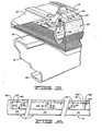
- FIG 1 shows a portion 10 of the roof of a conventional pre-fabricated building modified by using the standoff support device of the present invention, the roof 10 including primary structural members 12, secondary structural members 14 and corrugated roof panels 16.
- the primary structural members 12 comprise vertical columns 18 and the generally horizontal rafters 20 supported by the columns 18 and interconnected by bolts (not shown) to form an apex 22.
- the secondary structural members 14 or purlins have a Z-cross-section formed by oppositely extending flanges 24 and 26.
- the roof panels 16 are fastened indirectly to the purlins 14 which extend substantially the length of the roof 10 and which are connected to the rafters 20 via conventional connectors (not shown).
- Eave struts 28 are supported along the edge of the building by outwardly extending supports 29 which are connected via conventional connectors (not shown) to the vertical columns 18.
- conventional connectors not shown
- Other details of the pre-fabricated building depicted in Figure 1 are either not described or omitted from the drawings in order to simplify the present disclosure.
- the established method for insulating a pre-fabricated building roof is to place rolls of insulated material 30 over the purlins 14 so that the insulation is supported by the flanges 24.
- the roof panels 16 are then positioned directly on top of the insulation 30 and bolted to the flanges 24 in the manner shown in Figure 2A in which a screw 32 extends from the top through the panel 16 and threadingly engages a predrilled hole in the flange 24 of the underlying purlin 14. As the screw 32 is tightened, the panel member is deformed, and a dimple 33 results around the head of the screw 32.
- the insulation 30 which is normally compressible mineral or chopped glass fibre insulation, such as Fiberglass (R.T.M.), and which can be reduced to less than 15 percent of its original thickness as it is constricted between the purlin 14 and the panel member 16.
- FIG. 2B One prior art solution to this heat loss is shown in Figure 2B, in which like numerals designate those elements which are identical to those depicted in Figure 2A.
- An insulation board 36 is disposed above the flange 24 between the insulation 30 and the roof panel 16 so that the screw 32A passes through the insulation board 36, through the insulation 30, and attaches to the flange 24.
- the insulation board 36 serves to spread the compressive force of the fastened roof panel 16 at the screws 32A over a greater area of the insulation 30, and although this is constricted at 34A in the same manner as shown in Figure 2A, the combined thickness of the insulation board 36 and the compressed insulation is greater.
- the insulation 30 is still compressed and there are voids 38 between the insulation board 36, the roof panel 16 and the insulation 30, the result of which is even greater deterioration of the insulating quality at the connecting joints.
- the insulation board 36 is normally made of a relatively soft material, so that it is crushed by the screw 32A, resulting in increased dimpling of the panel 16, and ponding of water in the exaggerated dimples 33A brings about even greater corrosion.
- the roof panels 16 ( Figure 1) are supported by standoff support devices 40 which are secured to the flanges 24 of the purlins 14.
- the roof panels 16 are not attached directly to the underlying purlins as in both Figure 2A and Figure 2B. Rather, the roof panels 16 are attached to the standoff support devices 40 which are attached to the purlins 14 via fasteners that extend through the insulation material 30.
- insulation material 30 is supported on the upper flange 24 of purlin 14 and the standoff support device 40 is fastened to the flange 24 of the purlin 14 by a plurality of fastener assemblies 42.
- the insulation 30 and the standoff support device 40 is shown partially removed at 43 so as to show the fastener assembly 42 more fully.
- the standoff support device 40 comprises a channel shaped spacer member 44 having an upper first support surface 46 and a lower second support surface 48.
- the support member 44 has a plurality of fastener apertures 50 as best shown in Figure 4.
- the fastener assemblies 42 extend through the fastener apertures 50 to attach to the underlying substrate or purlin 14 in the manner described more fully hereinbelow. While the locations of the fastener apertures 50 may assume a variety of layout patterns, the offset pattern shown in Figure 4 is believed to be beneficial in providing greater stability to an imposed load.
- the standoff support device 40 shown in broken view in Figure 4 has a first end 52 and a second end 54, a portion of the first end 52 being shaped in the form of a protruding tag 56.
- a second identical standoff support device 40A is disposed in end-to-end alignment with the support device 40, and its tag 56A is received in the channel web of end 54 of device 40.
- a plurality of standoff support devices interjoin to provide a continuously extending upper or first surface 46 along the length of the supporting purlin 40, thus providing stability of the standoff support devices 40 supported by a single purlin 14, and further providing a guide piece to a workman as he interlocks each standoff support device 40 to those already attached to the underlying purlin during installation.
- a channel support bridge 60 ( Figure 3), provided at the overlapping edges of adjacent roof panels 16, has a bridge portion 62 which is supported at its opposite ends on the first support surface 46 by attachment of clips 64, disposed in appropriately disposed slots 66 (as shown in Figure 4).
- the bridge portion 62 is configured to have a profile which will mate with the overlapping edges of the roof panels 16 which are attached to the panel support bridge via conventional bolts (not shown) after a sealant is disposed therebetween.
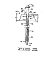
- the fastener assembly 42 depicted in Figure 5 comprises a column 70 having a first end 72 and a second end 74, the column 70 also having a channelway 76 extending between the ends 72 and 74.
- Each of the fastener apertures 50 is upset such that the internal surface 78 of the aperture 50 is flared away from the surface 46 in the manner shown.
- This provides a recess 80 to receive the first end 72 of the column 70, and the first end 72 is wedged or welded in the recess 80.
- the illustrated column 70 is a tube column which is connected to the support member 44 at its first end 72, and which is tapered at its second end 74.
- the channelway 76 is substantially axially aligned and communicates with the respective aperture 50 with which it is associated.
- the fastener assembly 42 also comprises an elongated fastener member 82 which has a first end 84, a body portion 86 and a second end 88.
- the first end 84 has a bolt head configuration for engagement by an appropriately sized wrench for rotating the fastener member 82, and is optionally provided with a washer 90.
- the second end 88 serves as a self-drilling/self-tapping screw and comprises a drill bit end 92, the body portion 86 having a threaded portion 94 adjacent the drill bit end 92.
- the fastener member 82 is disposed with its body portion extending through the fastener aperture 50 and the channelway 76.
- the tapered second end of the column 70 partially closes the channelway 76 sufficiently to receive the drill bit end 92 in a friction fit therewith, permitting the second end 88 to protrude from the end of the channelway 76.
- This arrangement provides for the retention of the fastener member 82 in an assembled position with the column 70, ready for penetration of the insulation material 36 and for securement to the purlin 14.
- the column 70 is shown as having an inwardly crimped portion 96 to assist in retaining the fastener member 82, the crimping being effected once the body portion 86 is positioned in the column at some convenient position clear of the threaded portion 94.
- the dimensional proportions of the fastener assembly are chosen such that the distance between the top surface of the flange 24 and the second support surface 48 of the support member 44, once the fastener member 82 is adequately tightened to the flange 24, is approximately equal to, or somewhat greater than, the thickness of the insulation blanket 30 so that the latter is not compressed.
- the dimensional proportions of the fastener assemblies 40,100 may be altered as desired to accommodate the insulation being installed.
- the insulation blanket is rolled over the purlins so that one or more widths of the blanket extend continuously from one side of the building to the other, with each of the widths of insulation passing over the apex of the building. Once in place, each of the widths of insulation blanket is cut to required length and weighted at each of its ends so as to tautly stretch each width of insulation over the rows of purlins.
- Each standoff support device 40 will be pre-assembled prior to use, so that a fastener assembly 42 js associated with each aperture 50 in the assembled position as depicted in Figure 5.
- the first standoff support device 40 to be placed at the edge of the purlin 14 will be generally aligned with the longitudinal axis of the purlin to which it is to be attached and positioned with the drill bit ends 92 of all of its fastener assemblies 42 resting upon the top layer of the insulation 30, this being in most cases, a moisture impregnable vapour barrier which is normally a vinvl film reinforced with some type of fibre.
- the drill bit ends 92 will easily penetrate the insulation and its vapour barrier, causing minimal disturbance to either the insulation or its vapour barrier. As the fastener assemblies 42 are pushed through the insulation 30, the drill bit ends 92 will come to rest on the flange 24 of the purlin 14.
- the alignment of the longitudinal axis of the initially placed standoff support device 40 can be achieved visually, or the proper alignment can be determined by the use of an aligning tool (not shown).
- This aligning tool is placed so as to abut with the end of a purlin, and it should provide an aligning tang protrusion, similar to the tang 56 shown in Figure 4, which will be receivable within the channel portion of the second end 54 of the standoff support device initially being positioned on the underlying purlin 14.
- an aligning tang protrusion can alternatively be provided by attaching or forming a guide member at one or both ends of each purlin 14, with the guide member having a protruding tang or the like, which serves to guide the placement of the initially positioned standoff support device.
- the second standoff support device 40 can be easily positioned by placing the channel of its second end 54 over the protrudinq.tang 56 of the first end 52 of the already positioned device 40. Once this interlocking step is accomplished, the fastener assemblies 42 of the second standoff support device 40 are pushed through the insulation 30 and secured to the, purlin in the manner described for the first placed standoff support device 40. These steps are repeated until a row of aligned standoff support devices 40 extend the combined distance of the widths of the insulation 30. In like manner, a row of standoff support devices 40 is provided for each of the purlins.
- the roof panels 16 are positioned onto the first support surfaces 46 of the standoff support device 40, and to attach the roof panels 16 to the standoff support devices 40 with conventional screws.
- the installation of the panels 16 is made much easier with the use of the standoff support devices 40 constructed in accordance with the present invention.
- the rows of axially aligned and fixed standoff support devices 40 serve as a solid insulation bridge and provide a solid footing for the panels. Further, they provide the installer with a visual guide to aid in the placement of screw members through the panel members 16, providing confidence that each screw member used to fasten the roof panel 16 will be anchored to underlying solid structural members, which,in this case, will be the underlying standoff support devices 40.
- the pre-penetration integrity of the insulation is substantially maintained since the fastener assemblies 42 cause minimal disturbance to the insulation material.
- Rotational energy applied to the headed ends 84 of the fastener members 82 serve to vibrate the loose insulation fibres, causing the insulation to "fill out", and since the elongated fastener assemblies 42 are relatively small in relation to the supported areas of the standoff support devices 40, the insulation is substantially unchanged from its pre-penetration.
Landscapes
- Engineering & Computer Science (AREA)
- Architecture (AREA)
- Mechanical Engineering (AREA)
- Civil Engineering (AREA)
- Structural Engineering (AREA)
- General Engineering & Computer Science (AREA)
- Connection Of Plates (AREA)
- Building Environments (AREA)
- Roof Covering Using Slabs Or Stiff Sheets (AREA)
Applications Claiming Priority (2)
| Application Number | Priority Date | Filing Date | Title |
|---|---|---|---|
| US93173 | 1979-11-13 | ||
| US06/093,173 US4329823A (en) | 1979-11-13 | 1979-11-13 | Support spacer apparatus |
Related Parent Applications (2)
| Application Number | Title | Priority Date | Filing Date |
|---|---|---|---|
| EP19800902380 Division EP0040239A4 (de) | 1979-11-13 | 1980-11-12 | Abstandshalter. |
| EP80902380.7 Division | 1980-11-12 |
Publications (1)
| Publication Number | Publication Date |
|---|---|
| EP0092853A2 true EP0092853A2 (de) | 1983-11-02 |
Family
ID=22237561
Family Applications (2)
| Application Number | Title | Priority Date | Filing Date |
|---|---|---|---|
| EP19800902380 Ceased EP0040239A4 (de) | 1979-11-13 | 1980-11-12 | Abstandshalter. |
| EP83104757A Withdrawn EP0092853A2 (de) | 1979-11-13 | 1980-11-12 | Verfahren zur Herstellung eines vorgefertigten Gebäudes |
Family Applications Before (1)
| Application Number | Title | Priority Date | Filing Date |
|---|---|---|---|
| EP19800902380 Ceased EP0040239A4 (de) | 1979-11-13 | 1980-11-12 | Abstandshalter. |
Country Status (4)
| Country | Link |
|---|---|
| US (1) | US4329823A (de) |
| EP (2) | EP0040239A4 (de) |
| CA (1) | CA1136825A (de) |
| WO (1) | WO1981001436A1 (de) |
Cited By (5)
| Publication number | Priority date | Publication date | Assignee | Title |
|---|---|---|---|---|
| FR2580906A1 (fr) * | 1985-04-24 | 1986-10-31 | Rossi & Catelli Spa | Procede pour le raffinage de produits alimentaires et installation pour la mise en oeuvre du procede. |
| FR2669667A1 (fr) * | 1990-11-23 | 1992-05-29 | Lr Etango | Cale d'epaisseur preformee autofixable pour toiture. |
| FR2677064A1 (fr) * | 1991-05-28 | 1992-12-04 | Soplachim | Dispositif pour la realisation d'une toiture a partir de plaques. |
| FR2843988A1 (fr) | 2002-09-03 | 2004-03-05 | Materiel D Elevage Forezien | Structure de toiture pour batiment |
| CN102595755A (zh) * | 2012-03-02 | 2012-07-18 | 福州顺康环保科技开发有限公司 | 等离子体发生器固定调节装置 |
Families Citing this family (58)
| Publication number | Priority date | Publication date | Assignee | Title |
|---|---|---|---|---|
| US5857292A (en) * | 1979-11-13 | 1999-01-12 | Harold Simpson, Inc. | Roof support apparatus |
| US4597234A (en) * | 1979-11-13 | 1986-07-01 | Harold Simpson, Inc. | Standing seam roof assembly |
| US4525967A (en) * | 1979-11-13 | 1985-07-02 | Encon Products, Inc. | Support spacer apparatus for a built-up roof |
| US4348846A (en) * | 1980-10-02 | 1982-09-14 | Butler Manufacturing Company | Insulated roof |
| US4446664A (en) * | 1981-03-23 | 1984-05-08 | Harkins Daniel J | Insulation system |
| US4573298A (en) * | 1981-03-23 | 1986-03-04 | Thermal Design, Inc. | Building insulation system |
| USD282627S (en) | 1983-01-31 | 1986-02-18 | Encon Products, Inc. | Support spacer |
| SE444833B (sv) * | 1983-02-10 | 1986-05-12 | Plannja Ab | Anordning vid isolerat yttertak for forankring av en takteckning av plat samt yttertakkonstruktion forsedd med denna anordning |
| US4473984A (en) * | 1983-09-13 | 1984-10-02 | Lopez Donald A | Curtain-wall masonry-veneer anchor system |
| US4651489A (en) * | 1983-10-24 | 1987-03-24 | Amca International | Insulated roofing structure |
| US5737894A (en) * | 1984-01-04 | 1998-04-14 | Harold Simpson, Inc. | Standing seam assembly |
| SE454786B (sv) * | 1984-02-10 | 1988-05-30 | Leif Ekstrom | Anordning for forankring av tva element med mellanrum vid varandra |
| US4747249A (en) * | 1985-11-01 | 1988-05-31 | Amca International Corporation | Subpurlin and attachment assembly |
| US4791770A (en) * | 1985-11-01 | 1988-12-20 | Amca International Corporation | Subpurlin and attachment assembly |
| US4676042A (en) * | 1985-11-01 | 1987-06-30 | Amca International Corporation | Subpurlin and attachment assembly |
| SE458459B (sv) * | 1987-02-16 | 1989-04-03 | Plannja Ab | Foerfarande och anordning vid utlaeggning av profilerad plaat |
| US5636488A (en) * | 1993-06-23 | 1997-06-10 | Stramit Corporation Limited | Panel and clip arrangement |
| FR2713687B1 (fr) * | 1993-12-15 | 1996-03-01 | Smac Acieroid | Dispositif de support d'une surtoiture, et ensemble couverture-surtoiture correspondant. |
| US6301853B1 (en) | 1995-06-07 | 2001-10-16 | Harold Simpson, Inc. | Standing seam roof assembly |
| US7574839B1 (en) | 1995-06-07 | 2009-08-18 | Harold Simpson, Inc. | Roof assembly having increased resistance to sidelap shear |
| EP0767283A1 (de) * | 1995-10-03 | 1997-04-09 | Isover Saint-Gobain | Wasserdichte Dachabdeckung |
| DE19640585C2 (de) | 1996-10-01 | 2001-05-23 | Sfs Ind Holding Ag Heerbrugg | Befestigungselement zum Befestigen von Isolationsbahnen oder -platten und gegebenenfalls zusätzlichen Abdichtungsbahnen auf einem festen Unterbau sowie Verfahren zur Vormontage einer Unterlegscheibe an einem Schraubenschaft |
| US6240682B1 (en) | 1998-10-19 | 2001-06-05 | V.P. Buildings, Inc. | Roof bracket |
| US6247288B1 (en) | 1999-09-09 | 2001-06-19 | Guardian Fiberglass, Inc. | Roof fabric dispensing device |
| US6595455B2 (en) | 2000-10-26 | 2003-07-22 | Guardian Fiberglass, Inc. | Rolled fabric dispensing apparatus and fall protection system and method |
| US6705059B2 (en) | 2001-09-27 | 2004-03-16 | Guardian Fiberglass, Inc. | Rolled fabric carriage apparatus |
| US6694693B2 (en) * | 2002-03-11 | 2004-02-24 | Robert J. Alderman | Insulation block for roof structure |
| AU2002325086B2 (en) * | 2002-03-18 | 2008-05-01 | Bluescope Steel Limited | A roofing system |
| US20050279043A1 (en) * | 2004-06-18 | 2005-12-22 | Joseph Bronner | Wall anchor system and method |
| US20100037552A1 (en) * | 2008-08-13 | 2010-02-18 | Joseph Bronner | Side mounted drill bolt and threaded anchor system for veneer wall tie connection |
| AU2010203122B2 (en) * | 2009-07-21 | 2016-10-06 | Roofing Accessories No 2 Pty Ltd | Building support system |
| US8544228B2 (en) * | 2009-10-27 | 2013-10-01 | Joseph Bronner | Winged anchor and spiked spacer for veneer wall tie connection system and method |
| US8371083B2 (en) * | 2010-09-30 | 2013-02-12 | Bluescope Buildings North America, Inc. | Retrofit roof assembly |
| CN103210161B (zh) * | 2010-11-15 | 2015-07-29 | 蓝野建筑北美有限公司 | 隔热系统和用于对金属屋顶进行隔热的系统 |
| US8621798B2 (en) | 2010-12-27 | 2014-01-07 | Lionel E. Dayton | Construction insulating panel |
| CA2832216C (en) | 2011-04-06 | 2017-07-11 | Bluescope Buildings North America, Inc. | Bridging thermal block system and method |
| US8596010B2 (en) | 2011-05-20 | 2013-12-03 | Mitek Holdings, Inc. | Anchor with angular adjustment |
| US8555596B2 (en) | 2011-05-31 | 2013-10-15 | Mitek Holdings, Inc. | Dual seal tubular anchor for cavity walls |
| US8516763B2 (en) * | 2011-06-02 | 2013-08-27 | Mitek Holdings, Inc. | Thermally isolating tubule for wall anchor |
| US8800241B2 (en) | 2012-03-21 | 2014-08-12 | Mitek Holdings, Inc. | Backup wall reinforcement with T-type anchor |
| US8661766B2 (en) | 2012-06-22 | 2014-03-04 | Mitek Holdings, Inc. | Anchor with angular adjustment |
| USD706127S1 (en) | 2012-07-26 | 2014-06-03 | Mitek Holdings, Inc. | Wing nut anchor having discontinuous threads |
| USD702544S1 (en) | 2012-07-26 | 2014-04-15 | Mitek Holdings, Inc. | Thermal wing nut anchor having continuous threads |
| US8881479B2 (en) * | 2012-08-09 | 2014-11-11 | Bluescope Buildings North America, Inc. | Wall system with vapor barrier securement |
| US8844230B2 (en) * | 2012-09-14 | 2014-09-30 | Daniel J. Harkins | Building insulation system |
| US9441371B1 (en) * | 2012-09-14 | 2016-09-13 | Daniel J. Harkins | Building insulation system |
| CA2973726C (en) * | 2015-01-19 | 2022-12-06 | Basf Se | Wall assembly having a spacer |
| US10407892B2 (en) | 2015-09-17 | 2019-09-10 | Columbia Insurance Company | High-strength partition top anchor and anchoring system utilizing the same |
| USD846973S1 (en) | 2015-09-17 | 2019-04-30 | Columbia Insurance Company | High-strength partition top anchor |
| US20170159285A1 (en) | 2015-12-04 | 2017-06-08 | Columbia Insurance Company | Thermal wall anchor |
| US10385571B2 (en) | 2016-05-24 | 2019-08-20 | American Buildings Company | Seam clips and roof decking systems utilizing the seam clips |
| RU172426U1 (ru) * | 2016-08-24 | 2017-07-07 | Игорь Викторович Прохоров | Металлическая гибкая связь |
| US11180919B1 (en) * | 2018-03-13 | 2021-11-23 | G. Paul Nelson, Jr. | Metal roof/wall apparatus including sliding clips |
| CN108590007A (zh) * | 2018-03-14 | 2018-09-28 | 森特士兴集团股份有限公司 | 一种抗台风、防渗漏的金属屋面系统 |
| JP7307590B2 (ja) * | 2019-05-17 | 2023-07-12 | 日鉄鋼板株式会社 | 二重折板屋根構造、屋根改修構造 |
| FR3097694B1 (fr) * | 2019-06-24 | 2021-07-09 | Schneider Electric Ind Sas | Armoire électrique avec panneau rapporté |
| USD1053389S1 (en) | 2020-03-26 | 2024-12-03 | Nucor Corporation | Support member for roof panel offset |
| US11536034B2 (en) | 2020-03-26 | 2022-12-27 | Nucor Corporation | Insulated roof systems, support members thereof, and method of installing |
Family Cites Families (26)
| Publication number | Priority date | Publication date | Assignee | Title |
|---|---|---|---|---|
| US2256961A (en) * | 1940-01-24 | 1941-09-23 | Ernest W Pearson | Refrigerator car insulation and method of applying it |
| US2590687A (en) * | 1948-06-23 | 1952-03-25 | Robertson Co H H | Building structure |
| US3055147A (en) * | 1955-06-10 | 1962-09-25 | Overly Mfg Company | Roof construction |
| GB885722A (en) | 1957-06-13 | 1961-12-28 | John Ryan Mckee | Improvements in or relating to fasteners for fixing together two structural elements |
| US3031044A (en) * | 1957-11-04 | 1962-04-24 | R C Mahon Company | Fire retardant wall construction |
| US2993110A (en) * | 1958-02-17 | 1961-07-18 | Nelson Stud Welding Division O | Corrosion inhibiting component for metal construction and method of using same |
| US2999571A (en) * | 1958-09-12 | 1961-09-12 | Peter H Huber | Powder-actuated fastener |
| US3019864A (en) * | 1959-10-12 | 1962-02-06 | Tempmaster Corp | Lagging mount |
| US3054482A (en) * | 1961-04-04 | 1962-09-18 | Robertson Co H H | Wall structure |
| US3210896A (en) * | 1963-08-20 | 1965-10-12 | Kenneth D Detman | Weather protector for roofs |
| NL128090C (de) * | 1964-06-18 | 1900-01-01 | ||
| FR1409939A (fr) * | 1964-07-24 | 1965-09-03 | Michelin & Cie | Tige de fixation d'éléments de couverture ondulés pour toitures ou bardages |
| US3394516A (en) * | 1965-07-06 | 1968-07-30 | Armco Steel Corp | Spacer |
| US3474583A (en) * | 1968-09-11 | 1969-10-28 | Robertson Co H H | Insulated metal wall structure |
| DE7012459U (de) * | 1970-04-06 | 1970-08-27 | Grebau Greschbach Ind | Abstandshalter. |
| US3900995A (en) * | 1971-11-22 | 1975-08-26 | Kurt Ehrenberg | Adjustable substructure for installing sheet roof |
| US3803791A (en) * | 1972-12-18 | 1974-04-16 | W Turnbull | Device for and method of mounting wall facings |
| US3850073A (en) * | 1973-03-07 | 1974-11-26 | Berryfast Inc | Fastener |
| CA998266A (en) * | 1973-10-10 | 1976-10-12 | Charles E. Gutshall | Controlled-drive sealing fastener |
| DE2514259C2 (de) | 1975-04-01 | 1987-04-09 | Wolfgang Dipl.rer.pol. 3100 Celle Haacke | Dachkonstruktion mit plattenförmigen Isolierstoffbauelementen sowie Abstandhalter für die Dachkonstruktion |
| FI51728C (fi) | 1976-03-16 | 1977-03-10 | Jarmo Jaervinen | Kiinnike. |
| DE2611395C2 (de) * | 1976-03-18 | 1978-02-16 | Opheis Gmbh & Co | Vorrichtung zum Befestigen profilierter Dacheindeckungsplatten auf einer Dachkonstruktion |
| US4081938A (en) * | 1976-12-13 | 1978-04-04 | Ralph Bertacchi | Standoff insulated panel mounting |
| US4102103A (en) * | 1977-02-14 | 1978-07-25 | Emil Marcmann | Breeching insulation panels and method of construction |
| US4114338A (en) * | 1977-05-09 | 1978-09-19 | Armco Steel Corporation | Reinforcing plate for overlapped joints |
| US4250678A (en) * | 1979-04-30 | 1981-02-17 | Transco, Inc. | Mounting for insulated panel |
-
1979
- 1979-11-13 US US06/093,173 patent/US4329823A/en not_active Expired - Lifetime
-
1980
- 1980-11-12 WO PCT/US1980/001508 patent/WO1981001436A1/en not_active Ceased
- 1980-11-12 EP EP19800902380 patent/EP0040239A4/de not_active Ceased
- 1980-11-12 CA CA000364449A patent/CA1136825A/en not_active Expired
- 1980-11-12 EP EP83104757A patent/EP0092853A2/de not_active Withdrawn
Cited By (9)
| Publication number | Priority date | Publication date | Assignee | Title |
|---|---|---|---|---|
| FR2580906A1 (fr) * | 1985-04-24 | 1986-10-31 | Rossi & Catelli Spa | Procede pour le raffinage de produits alimentaires et installation pour la mise en oeuvre du procede. |
| FR2669667A1 (fr) * | 1990-11-23 | 1992-05-29 | Lr Etango | Cale d'epaisseur preformee autofixable pour toiture. |
| FR2677064A1 (fr) * | 1991-05-28 | 1992-12-04 | Soplachim | Dispositif pour la realisation d'une toiture a partir de plaques. |
| GR920100209A (el) * | 1991-05-28 | 1993-03-31 | Soplachim Sa | Συσκευή για την κατασκευή μιας σκεπής από πλάκες. |
| ES2063640A2 (es) * | 1991-05-28 | 1995-01-01 | Soplachim | Dispositivo para la realizacion de una techumbre a partir de placas. |
| BE1006842A3 (fr) * | 1991-05-28 | 1995-01-03 | Soplachim Sa | Dispositif pour la realisation d'une toiture a partir de plaques. |
| FR2843988A1 (fr) | 2002-09-03 | 2004-03-05 | Materiel D Elevage Forezien | Structure de toiture pour batiment |
| CN102595755A (zh) * | 2012-03-02 | 2012-07-18 | 福州顺康环保科技开发有限公司 | 等离子体发生器固定调节装置 |
| CN102595755B (zh) * | 2012-03-02 | 2014-09-24 | 福州顺康环保科技开发有限公司 | 等离子体发生器固定调节装置 |
Also Published As
| Publication number | Publication date |
|---|---|
| WO1981001436A1 (en) | 1981-05-28 |
| EP0040239A1 (de) | 1981-11-25 |
| EP0040239A4 (de) | 1982-03-22 |
| US4329823A (en) | 1982-05-18 |
| CA1136825A (en) | 1982-12-07 |
Similar Documents
| Publication | Publication Date | Title |
|---|---|---|
| EP0092853A2 (de) | Verfahren zur Herstellung eines vorgefertigten Gebäudes | |
| US4516371A (en) | Insulation and paneling apparatus and method | |
| US4361993A (en) | Frameless enclosure assembly | |
| US4602468A (en) | Roof clip assembly for a roof system | |
| CA1164619A (en) | Insulated roof | |
| US5857292A (en) | Roof support apparatus | |
| US4472920A (en) | Method of insulating and sealing and building | |
| US5901518A (en) | Building insulation system with fall protection | |
| US4528789A (en) | Insulated roof system | |
| US8181410B2 (en) | Insulation system and method for pre-engineered buildings | |
| US4494343A (en) | Structure for retrofitting corrugated building exteriors | |
| EP0129404B1 (de) | Befestigungen, einschliesslich Schrauben und Klemmplatten | |
| US5704170A (en) | Apparatus for roof support | |
| US4597234A (en) | Standing seam roof assembly | |
| US5177922A (en) | Leaktight covering fixed to a framework | |
| US20120255252A1 (en) | Bridging thermal block system and method | |
| US5005323A (en) | Apparatus for securing a roofing support spacer to underlying support structures | |
| US8661763B2 (en) | Purlin brace systems | |
| US4192108A (en) | Frameless metal building | |
| US4525967A (en) | Support spacer apparatus for a built-up roof | |
| CA1180869A (en) | Alternating v-truss roof system and method of erection | |
| JP3729488B2 (ja) | パネルの受金具構造 | |
| GB2063961A (en) | Cladding building structures | |
| JP2017145607A (ja) | 木造陸屋根の支柱取付構造 | |
| EP0035148A1 (de) | Konstruktion zum nachträglichen Ausbau einer gewellten Gebäudeaussenseite |
Legal Events
| Date | Code | Title | Description |
|---|---|---|---|
| PUAI | Public reference made under article 153(3) epc to a published international application that has entered the european phase |
Free format text: ORIGINAL CODE: 0009012 |
|
| 17P | Request for examination filed |
Effective date: 19830514 |
|
| AC | Divisional application: reference to earlier application |
Ref document number: 40239 Country of ref document: EP |
|
| AK | Designated contracting states |
Designated state(s): DE FR GB NL |
|
| STAA | Information on the status of an ep patent application or granted ep patent |
Free format text: STATUS: THE APPLICATION HAS BEEN WITHDRAWN |
|
| 18W | Application withdrawn |
Withdrawal date: 19850125 |
|
| RIN1 | Information on inventor provided before grant (corrected) |
Inventor name: SIMPSON, HAROLD G. |