US4747249A - Subpurlin and attachment assembly - Google Patents
Subpurlin and attachment assembly Download PDFInfo
- Publication number
- US4747249A US4747249A US06/931,401 US93140187A US4747249A US 4747249 A US4747249 A US 4747249A US 93140187 A US93140187 A US 93140187A US 4747249 A US4747249 A US 4747249A
- Authority
- US
- United States
- Prior art keywords
- subpurlin
- assembly
- structural
- roof
- bearing surface
- Prior art date
- Legal status (The legal status is an assumption and is not a legal conclusion. Google has not performed a legal analysis and makes no representation as to the accuracy of the status listed.)
- Expired - Lifetime
Links
- 238000009413 insulation Methods 0.000 claims description 15
- 230000006835 compression Effects 0.000 claims description 9
- 238000007906 compression Methods 0.000 claims description 9
- 238000009434 installation Methods 0.000 abstract description 6
- 230000000712 assembly Effects 0.000 abstract description 5
- 238000000429 assembly Methods 0.000 abstract description 5
- 239000011810 insulating material Substances 0.000 description 8
- 230000003014 reinforcing effect Effects 0.000 description 5
- 239000003351 stiffener Substances 0.000 description 5
- 230000008602 contraction Effects 0.000 description 4
- 239000000463 material Substances 0.000 description 4
- XLYOFNOQVPJJNP-UHFFFAOYSA-N water Substances O XLYOFNOQVPJJNP-UHFFFAOYSA-N 0.000 description 4
- 230000013011 mating Effects 0.000 description 2
- 239000002184 metal Substances 0.000 description 2
- 239000004566 building material Substances 0.000 description 1
- 230000015556 catabolic process Effects 0.000 description 1
- 238000005260 corrosion Methods 0.000 description 1
- 230000007797 corrosion Effects 0.000 description 1
- 230000007423 decrease Effects 0.000 description 1
- 238000006731 degradation reaction Methods 0.000 description 1
- 238000000034 method Methods 0.000 description 1
- 230000000284 resting effect Effects 0.000 description 1
- 238000007789 sealing Methods 0.000 description 1
- 125000006850 spacer group Chemical group 0.000 description 1
- 239000002023 wood Substances 0.000 description 1
Images


Classifications
-
- E—FIXED CONSTRUCTIONS
- E04—BUILDING
- E04D—ROOF COVERINGS; SKY-LIGHTS; GUTTERS; ROOF-WORKING TOOLS
- E04D3/00—Roof covering by making use of flat or curved slabs or stiff sheets
- E04D3/36—Connecting; Fastening
- E04D3/3601—Connecting; Fastening of roof covering supported by the roof structure with interposition of a insulating layer
- E04D3/3602—The fastening means comprising elongated profiles installed in or on the insulation layer
-
- E—FIXED CONSTRUCTIONS
- E04—BUILDING
- E04D—ROOF COVERINGS; SKY-LIGHTS; GUTTERS; ROOF-WORKING TOOLS
- E04D13/00—Special arrangements or devices in connection with roof coverings; Protection against birds; Roof drainage; Sky-lights
- E04D13/16—Insulating devices or arrangements in so far as the roof covering is concerned, e.g. characterised by the material or composition of the roof insulating material or its integration in the roof structure
- E04D13/1606—Insulation of the roof covering characterised by its integration in the roof structure
- E04D13/1612—Insulation of the roof covering characterised by its integration in the roof structure the roof structure comprising a supporting framework of roof purlins or rafters
- E04D13/1618—Insulation of the roof covering characterised by its integration in the roof structure the roof structure comprising a supporting framework of roof purlins or rafters with means for fixing the insulating material between the roof covering and the upper surface of the roof purlins or rafters
-
- E—FIXED CONSTRUCTIONS
- E04—BUILDING
- E04D—ROOF COVERINGS; SKY-LIGHTS; GUTTERS; ROOF-WORKING TOOLS
- E04D3/00—Roof covering by making use of flat or curved slabs or stiff sheets
- E04D3/36—Connecting; Fastening
- E04D3/3607—Connecting; Fastening the fastening means comprising spacer means adapted to the shape of the profiled roof covering
Definitions
- This invention relates to metal building systems and, more particularly, to an intermediate subpurlin for spacing roof panels above an underlying support structure
- a typical roof structure for metal buildings includes a structural support system covered by a plurality of overlapping roof panels.
- Roof panels are generally formed from sheet materials to define ribs and other contours which provide rigidity and strength to the panels. Mating ribs may be provided where panels overlap for improved interlocking and weather integrity.
- the structural support system and the roof panels may experience dimensional changes from thermal expansion and contraction. There is frequently differential movement between the roof panels and underlying structure. Where the roof panels are rigidly fixed to the underlying structure, stresses and physical deformation can be produced in the roof panels, particularly along panel widths perpendicular to the panel ribs.
- the roof panels are fastened to the underlying structure at low points or valleys in the panel contour. Water run-off and collection also occur along the panel valleys. Thus, the valley locations where fasteners penetrate the roof panels are often the source of water leakage and of roof panel degradation.
- a building roof structure may also include an insulating layer between the structural support system and the overlying roof panels.
- the thickness of the insulating layer may be considerably reduced where the roof panels are fixed to the structure. Compressing the insulating layer thickness greatly decreases the insulating effectiveness of the layer.
- U.S. Pat. No. 4,114,338 to Beck teaches a reinforcing plate for use beneath end lapped thin gauge sheets to provide structural support adjacent the joints for improved sealing.
- the reinforcing plate is elevated above the underlying insulation and is fastened to an underlying purlin through downwardly depending flanges having mounting slots therein.
- the roofing sheets are fixed to the reinforcing plates along valleys where water run-off and collection can occur.
- a subpurlin is provided in a contour effective to support roof panels without compressing underlying insulation while providing elevated fastening support areas and having a clip for slidably fastening the subpurlin to underlying support structure.
- a connector for interconnecting a subpurlin with a roof structural assembly.
- the connector slidably engages the subpurlin to permit thermal expansion and contraction of the roof deck panels attached to the subpurlin.
- the connector is also provided with a boss which spaces the sliding bearing surface above the roof structural assembly to permit insulation to be placed between the roof structural assembly and the subpurlin.
- the surface area of the contact surface between the boss and the roof structural assembly is much less than the bearing surface on which the subpurlin slides to minimize the compression of the insulation at the point of attachment between the connector and the roof structural assembly.
- a subpurlin for interconnecting a roof structural assembly and roof deck panels.
- the subpurlin is formed as an elongate member defining a plurality of slotted openings, each having a length which is effective to accommodate expansion and contraction movements of the roof deck panels relative to the underlying structural assembly.
- a connector is provided for slidably engaging the elongate member adjacent the roof structural assembly and beneath the roof deck panels.
- the connector includes a washer defining a bearing surface, and a ferrule which slidably engages a slotted opening in the elongate member, where the ferrule has a length which is effective to maintain the washer above the opening and in spaced relationship with the elongate member.
- a method of assembly is also provided for forming an insulated roof structure over a plurality of underlying structural members.
- Insulating material is placed above and generally transverse to the structural members.
- a first subpurlin is placed above the insulating material and along one of the structural members, where the subpurlin has a plurality of low cell areas adjacent the structural member which define respective expansion slots therethrough, and a plurality of high cell areas extending above the insulating material.
- the subpurlin includes a plurality of spanner sections between and supported by the low cell areas.
- Bearing surfaces are formed above the expansion slots and spaced above the slots on ferrules extending through the slots. The bearing surfaces are fastened to the structural members through the ferrules, each of the ferrules maintaining its associated bearing surface spaced above the expansion slot.
- An improved building assembly having a plurality of overhead structural members, an insulating layer, and a plurality of overlapping external roof panels, where a plurality of subpurlins are provided for supporting and spacing the roof panels above the structural members.
- Connectors attach the subpurlins to the structural members in a manner which enables relative thermal movement between the roof panels and the structural members.
- Each subpurlin is an elongate member defining a plurality of slotted openings, each having a length which is effective to accommodate the expansion and contraction movement of the roof deck panels relative to the structural assembly.
- the connector slidably engages the elongate subpurlin adjacent the roof structural assembly and beneath the roof deck panels.
- Each connector includes a washer which defines a bearing surface and a ferrule which slidably engages a subpurlin slotted opening and which has a length effective to maintain the washer above the opening in a spaced apart relationship with the elongate member.
- FIG. 1 is a pictorial illustration of one embodiment of a subpurlin in accordance with the present invention.
- FIG. 2 is a pictorial illustration of one embodiment of a subpurlin fastening clip.
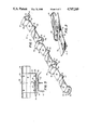
- FIG. 3 is a side elevation in partial cutaway of an installed subpurlin with clip.
- FIG. 4 is an exploded side view of an installation showing a sequence of assembly.
- FIG. 5 is a pictorial illustration of a building component assembly incorporating embodiments of the present invention.
- FIG. 6 is a perspective view of the underside of a connector forming one embodiment of the present invention illustrating the boss spacing the subpurlin sliding surface above the roof structural assembly.
- FIG. 7 is a bottom plan view of the connector.
- FIG. 8 is a side view of the connector mounted on the roof structural assembly illustrating the minimal compression of the insulation between the connector and the roof structural assembly.
- FIG. 9 is an end view of the connector mounted to the roof structural assembly illustrating the minimum compression of the insulation therebetween.
- Subpurlin 10 is formed as an elongate member having a lap end 12 and rib end 14. Lap end 12 mates with the rib end 14 of an adjacent subpurlin 10, as hereinafter explained.
- subpurlin 10 is about 36 inches long and three inches wide, a size consistent with conventional building materials.
- Subpurlin 10 defines a plurality of expansion slots 16 along its length.
- An expansion slot is included at lap end 12 and rib end 14 and at intermediate locations where subpurlin 10 contacts the underlying support structure.
- the configuration of the elongate subpurlin 10 includes intermediate bearing stiffeners 22, high cell ribs 24, low cell ribs 26 and connecting spanner sections 28.
- Spanner sections 28 are supported above underlying structural members by flanges at lap end 12 and rib end 14, by intermediate bearing stiffeners 22, and by low cell ribs 26.
- Bearing stiffeners 22 serve to provide the desired rigidity to spanner sections 28 at desired locations.
- Reinforcing embossments 18 provide additional strength at locations where subpurlin 10 is bent.
- Preferably low cell ribs 26 further define slots 16. Slots 16 have a length which is effective to enable relative thermal expansion movements to occur between the overlying roof structure and the underling structural members, as hereinafter explained.
- High cell ribs 24 may be provided in a variety of configurations. It is desirable, however, that the selected configuration be compatible with elongate ribs of the overlying roof deck panels to provide for attaching the deck panels to the high cell ribs 24.
- slider assembly 30 for joining subpurlin 10 with the underlying structural members.
- Slider tab 32 is formed as a ferrule for engaging expansion slots 16 in subpurlin 10 (see FIG. 1).
- Washer 34 is placed above ferrule 32 and defines a bearing surface for use in fastening the assembly together, as hereinafter explained.
- washer 34 is supported above ferrule 32 by connecting biasing arms 38 to form a unitary connector assembly 30 which is convenient for field installation.
- connecting slider assembly 30 is installed by urging washer 34 above a low cell rib area 26 of subpurlin 10 and along low cell rib 26 until ferrule 32 is engaged through expansion slot 16.
- Bottom sliding surface 36 may then be dimensionally formed to have the same length as the width of subpurlin 10 so that alignment is easily accomplished, either visually or by feel.
- Structural bearing surface 40 is placed adjacent an underlying structural assembly member, a fastener is inserted through washer 34 and ferrule 32, and the fastener is rotated to secure washer 34 against ferrule 32. While a threaded fastener 52 is shown, any suitable fastener can be used to suit the structural assembly member. A nail could be used when the structural assembly member is wood, for example.
- ferrule 32 The dimensions of ferrule 32 are selected such that expansion slot 16 slidably engages ferrule 32 when washer 34 is clamped against ferrule 32. Thus, low cell rib areas 26 slidably engage bottom sliding surface 36 as the assembly is fastened to the underlying support structure.
- Structural member 50 may be a purlin or may be a primary structural member such as a bar joist.
- Biasing arms 38 have been spread to move connecting slider assembly 30 about rib end 14 (as shown in FIG. 1) until ferrule 32 has engaged through expansion slot 16 (not shown).
- Structural bearing surface 40 of slider assembly 30 is placed adjacent structural member 50 and fastener 52 is installed to secure washer 34 adjacent ferrule 32 and connector assembly 30 to structural member 50.
- rib end 14 is fastened, but not clamped, to structural member 50 wherein expansion slot 16 (not shown) can slide about ferrule 32 and beneath washer 34 over sliding surface 36 to accommodate relative movement between the overlying roof panel and structural member 50.
- expansion slot 16 (not shown) can slide about ferrule 32 and beneath washer 34 over sliding surface 36 to accommodate relative movement between the overlying roof panel and structural member 50.
- a rib of roof panel 56 has been placed over high cell rib 24 adjacent rib end 14 and fastened to high cell rib 24 by fastener 58.
- FIG. 4 A typical installation sequence for installing subpurlins 10 and overlying roof panels 56 is shown in FIG. 4.
- a first subpurlin 10 is fastened to structural member 50 at intermediate low cell rib 26 with fastener 52 secured through connecting slider assembly 30.
- Intermediate bearing stiffeners 22 support spanner sections 28 above support member 50, forming insulation space 60 to accommodate insulating material without compressing the insulating material.
- Roof panel 56 is secured to high cell ribs 24 of subpurlin 10 with fastener 58. Installation of subpurlin 10 is completed except rib end 14 is not secured to support member 50 and the adjoining roof panel is not secured to high cell rib 24 adjacent rib end 14.
- Adjoining subpurlin 10a is next installed. Lap end 12a is placed adjacent rib end 14. Connector slider assembly 30a may be slipped over both flange areas where the ferrule 32 (FIG. 2) passes through the mating expansion slots (not shown) of lap end 12a and rib end 14. Fastener 52a now fixes slider assembly 30a to support member 50. Subpurlin 10a is then fixed along support member 50 by successively fastening slider assemblies 30b with fasteners 52b until rib end 14a is reached.
- subpurlin 10a is the last subpurlin in a given sheet run (i.e., the distance from eave to endlap, eave to ridge, etc.), then installation is completed by installing slider assembly 30c with fastener 52c. Otherwise the next subpurlin is placed adjacent rib end 14a, as hereinabove described.
- Roof sheets 56 and 56a are fastened to subpurlins 10 and 10a with fasteners 58, 58a, 58b at high cell ribs 24, 24a. It will be appreciated that fasteners 58, 58a, 58b are fixed to raised locations of roof sheet panels 56, 56a such that water properly drains away from fasteners 58, 58a, 58b and does not accumulate in a manner to cause leakage or corrosion of roof panel material adjacent the fasteners.
- FIG. 5 A pictorial illustration of a subpurlin assembly according to the present invention and installed on a structural support member having a layer of insulating material is shown in FIG. 5.
- Subpurlin 10 has been placed along support member 50 and fixed to support member 50 by fasteners fixed through connector slider assemblies 30.
- Low cell ribs 26 and bearing stiffeners 22 support spanner sections 28 above insulation 62 without any substantial compression of insulation 62.
- High cell ribs 24 extend above insulation 62 to support overlying roof panels (not shown) above insulation 62.
- the overlying roof panels (not shown) will be fastened to subpurlins 10.
- Subpurlins 10 will be slidingly fixed to support member 50 through connecting slider assemblies 30. Relative thermal movements transverse to support member 50 occur without producing strains on overlapping longitudinal ribs of the overlying roof panels 56 (not shown).
- the connector spaces the bottom sliding surface 36 on which the subpurlin 10 rests above the structural assembly member 50. This spacing is achieved by the boss 102 which forms part of the connector 30 and extends downwardly from the material forming the bottom sliding surface 36. As can be seen, the boss 102 tapers downwardly and inwardly at ends 104 to reduce the surface area of the structural bearing surface 40 actually resting on the structural assembly member 50. This minimizes the compression of the insulating material 100 yet provides a stable and secure attachment for the subpurlin on the structural assembly member.
- the bottom sliding surface 36 is 31/4" long to accommodate the 3" width of the subpurlin 10.
- the surface 36 is 11/4" wide to provide an adequate support surface for the subpurlin.
- the structural bearing surface 40 of the boss 102 is reduced to a contact surface with the structural assembly member 50 of only 5/16" wide by 11/2" long.
- the height of the boss was approximately 1/4", which is approximately the distance from the top of the structural assembly member 50 to the bottom sliding surface 36. With insulation of, for example, 5" uncompressed thickness, the use of the connector minimizes the necessary compression in order to provide a rigid connection between the subpurlins and the structural assembly members 50.
- the connector 30 is stamped from a single sheet of material into the shape as shown in the drawings and described herein.
Abstract
Description
Claims (5)
Priority Applications (1)
| Application Number | Priority Date | Filing Date | Title |
|---|---|---|---|
| US06/931,401 US4747249A (en) | 1985-11-01 | 1987-01-14 | Subpurlin and attachment assembly |
Applications Claiming Priority (2)
| Application Number | Priority Date | Filing Date | Title |
|---|---|---|---|
| US06/794,076 US4676042A (en) | 1985-11-01 | 1985-11-01 | Subpurlin and attachment assembly |
| US06/931,401 US4747249A (en) | 1985-11-01 | 1987-01-14 | Subpurlin and attachment assembly |
Related Parent Applications (1)
| Application Number | Title | Priority Date | Filing Date |
|---|---|---|---|
| US06/794,076 Continuation-In-Part US4676042A (en) | 1985-11-01 | 1985-11-01 | Subpurlin and attachment assembly |
Publications (1)
| Publication Number | Publication Date |
|---|---|
| US4747249A true US4747249A (en) | 1988-05-31 |
Family
ID=27121471
Family Applications (1)
| Application Number | Title | Priority Date | Filing Date |
|---|---|---|---|
| US06/931,401 Expired - Lifetime US4747249A (en) | 1985-11-01 | 1987-01-14 | Subpurlin and attachment assembly |
Country Status (1)
| Country | Link |
|---|---|
| US (1) | US4747249A (en) |
Cited By (8)
| Publication number | Priority date | Publication date | Assignee | Title |
|---|---|---|---|---|
| US20100251652A1 (en) * | 2009-04-07 | 2010-10-07 | Golden Matthew V | Vibration Isolation Mounting Clip |
| US20110173913A1 (en) * | 2010-01-19 | 2011-07-21 | Stan Bodsford | Insulated building structure and apparatus therefor |
| US8479460B1 (en) * | 2009-08-18 | 2013-07-09 | Consolidated Systems, Inc. | High shear roof deck system |
| US20140083037A1 (en) * | 2011-04-06 | 2014-03-27 | Bluescope Buildings North America, Inc. | Wall Insulation Systems And Stanchion |
| US20150292209A1 (en) * | 2012-11-16 | 2015-10-15 | Bluescope Steel Limited | End lap system for roof cladding sheets |
| AU2018219971B2 (en) * | 2008-06-25 | 2020-02-06 | Bluescope Steel Limited | Spacer |
| US10801197B2 (en) * | 2015-01-19 | 2020-10-13 | Basf Se | Wall assembly having a spacer |
| US11536034B2 (en) * | 2020-03-26 | 2022-12-27 | Nucor Corporation | Insulated roof systems, support members thereof, and method of installing |
Citations (13)
| Publication number | Priority date | Publication date | Assignee | Title |
|---|---|---|---|---|
| US3031044A (en) * | 1957-11-04 | 1962-04-24 | R C Mahon Company | Fire retardant wall construction |
| US3332186A (en) * | 1963-05-22 | 1967-07-25 | Solvay | System for securing corrugated sheeting |
| US3394516A (en) * | 1965-07-06 | 1968-07-30 | Armco Steel Corp | Spacer |
| US3975880A (en) * | 1975-04-28 | 1976-08-24 | All-State Industries, Inc. | Sheet metal batten roof or siding |
| US3998019A (en) * | 1975-08-18 | 1976-12-21 | Illinois Tool Works Inc. | Roof panel fastener and joint construction |
| US4081938A (en) * | 1976-12-13 | 1978-04-04 | Ralph Bertacchi | Standoff insulated panel mounting |
| US4114338A (en) * | 1977-05-09 | 1978-09-19 | Armco Steel Corporation | Reinforcing plate for overlapped joints |
| US4329823A (en) * | 1979-11-13 | 1982-05-18 | Encon Products, Inc. | Support spacer apparatus |
| US4361993A (en) * | 1979-11-13 | 1982-12-07 | Encon Products, Inc. | Frameless enclosure assembly |
| US4406106A (en) * | 1979-04-05 | 1983-09-27 | Dinges Kenneth N | Concealed fastener panel construction and method of installation |
| US4466224A (en) * | 1982-06-18 | 1984-08-21 | H. H. Robertson Company | Two-piece attachment clip for insulated roof or wall structure |
| US4486998A (en) * | 1982-05-07 | 1984-12-11 | H. H. Robertson Company | Concealed fastener roof or wall structure and method of assembly |
| US4651489A (en) * | 1983-10-24 | 1987-03-24 | Amca International | Insulated roofing structure |
-
1987
- 1987-01-14 US US06/931,401 patent/US4747249A/en not_active Expired - Lifetime
Patent Citations (13)
| Publication number | Priority date | Publication date | Assignee | Title |
|---|---|---|---|---|
| US3031044A (en) * | 1957-11-04 | 1962-04-24 | R C Mahon Company | Fire retardant wall construction |
| US3332186A (en) * | 1963-05-22 | 1967-07-25 | Solvay | System for securing corrugated sheeting |
| US3394516A (en) * | 1965-07-06 | 1968-07-30 | Armco Steel Corp | Spacer |
| US3975880A (en) * | 1975-04-28 | 1976-08-24 | All-State Industries, Inc. | Sheet metal batten roof or siding |
| US3998019A (en) * | 1975-08-18 | 1976-12-21 | Illinois Tool Works Inc. | Roof panel fastener and joint construction |
| US4081938A (en) * | 1976-12-13 | 1978-04-04 | Ralph Bertacchi | Standoff insulated panel mounting |
| US4114338A (en) * | 1977-05-09 | 1978-09-19 | Armco Steel Corporation | Reinforcing plate for overlapped joints |
| US4406106A (en) * | 1979-04-05 | 1983-09-27 | Dinges Kenneth N | Concealed fastener panel construction and method of installation |
| US4329823A (en) * | 1979-11-13 | 1982-05-18 | Encon Products, Inc. | Support spacer apparatus |
| US4361993A (en) * | 1979-11-13 | 1982-12-07 | Encon Products, Inc. | Frameless enclosure assembly |
| US4486998A (en) * | 1982-05-07 | 1984-12-11 | H. H. Robertson Company | Concealed fastener roof or wall structure and method of assembly |
| US4466224A (en) * | 1982-06-18 | 1984-08-21 | H. H. Robertson Company | Two-piece attachment clip for insulated roof or wall structure |
| US4651489A (en) * | 1983-10-24 | 1987-03-24 | Amca International | Insulated roofing structure |
Cited By (13)
| Publication number | Priority date | Publication date | Assignee | Title |
|---|---|---|---|---|
| AU2018219971B2 (en) * | 2008-06-25 | 2020-02-06 | Bluescope Steel Limited | Spacer |
| US8549809B2 (en) * | 2009-04-07 | 2013-10-08 | Kinetics Noise Control, Inc. | Vibration isolation mounting clip |
| US20100251652A1 (en) * | 2009-04-07 | 2010-10-07 | Golden Matthew V | Vibration Isolation Mounting Clip |
| US8479460B1 (en) * | 2009-08-18 | 2013-07-09 | Consolidated Systems, Inc. | High shear roof deck system |
| US8739486B2 (en) * | 2010-01-19 | 2014-06-03 | Stan Bodsford | Insulated building structure and apparatus therefor |
| US20110173913A1 (en) * | 2010-01-19 | 2011-07-21 | Stan Bodsford | Insulated building structure and apparatus therefor |
| US20140083037A1 (en) * | 2011-04-06 | 2014-03-27 | Bluescope Buildings North America, Inc. | Wall Insulation Systems And Stanchion |
| US9493947B2 (en) * | 2011-04-06 | 2016-11-15 | Richard R. McClure | Wall insulation systems and stanchion |
| US20150292209A1 (en) * | 2012-11-16 | 2015-10-15 | Bluescope Steel Limited | End lap system for roof cladding sheets |
| US10087633B2 (en) * | 2012-11-16 | 2018-10-02 | Bluescope Steel Limited | End lap system for roof cladding sheets |
| US10801197B2 (en) * | 2015-01-19 | 2020-10-13 | Basf Se | Wall assembly having a spacer |
| US11536034B2 (en) * | 2020-03-26 | 2022-12-27 | Nucor Corporation | Insulated roof systems, support members thereof, and method of installing |
| US11939771B2 (en) | 2020-03-26 | 2024-03-26 | Nucor Corporation | Insulated roof systems, support members thereof, and method of installing |
Similar Documents
| Publication | Publication Date | Title |
|---|---|---|
| US4651489A (en) | Insulated roofing structure | |
| US4495743A (en) | Standing seam roof system | |
| US4466224A (en) | Two-piece attachment clip for insulated roof or wall structure | |
| US5363624A (en) | Roofing and siding system | |
| US4476658A (en) | Standing seam roof system | |
| GB2122234A (en) | Insulated roof | |
| EP0119077B1 (en) | Roof insulation retention | |
| US4089145A (en) | Metal roof construction | |
| US4435937A (en) | Concealed fastener support for interlocked channel section panels | |
| US4747249A (en) | Subpurlin and attachment assembly | |
| US4676042A (en) | Subpurlin and attachment assembly | |
| US4914886A (en) | Device for laying out profiled sheet | |
| US4297825A (en) | Strut for space frames | |
| US4791770A (en) | Subpurlin and attachment assembly | |
| US4506479A (en) | Roof or wall covering and mounting member for a gutter bracket | |
| US6272807B1 (en) | Rain directional panel | |
| US2428361A (en) | Roofing | |
| US4574549A (en) | Adjustable roof insulation system | |
| GB2117026A (en) | Roof underlining and method of erection | |
| JP2633003B2 (en) | Thatched roof structure | |
| JPH0338334Y2 (en) | ||
| GB2279089A (en) | Clips for corrugated cladding sheets | |
| JP2898244B2 (en) | Support structure for folded roof | |
| JP2544069Y2 (en) | Terrace roof | |
| JPH0718817Y2 (en) | Mounting structure for metal roof plate |
Legal Events
| Date | Code | Title | Description |
|---|---|---|---|
| FEPP | Fee payment procedure |
Free format text: PAYOR NUMBER ASSIGNED (ORIGINAL EVENT CODE: ASPN); ENTITY STATUS OF PATENT OWNER: LARGE ENTITY |
|
| STCF | Information on status: patent grant |
Free format text: PATENTED CASE |
|
| FPAY | Fee payment |
Year of fee payment: 4 |
|
| CC | Certificate of correction | ||
| FPAY | Fee payment |
Year of fee payment: 8 |
|
| AS | Assignment |
Owner name: UNITED DOMINION INDUSTRIES, INC., NORTH CAROLINA Free format text: CHANGE OF NAME;ASSIGNOR:AMCA INTERNATIONAL CORPORATION;REEL/FRAME:009453/0176 Effective date: 19900425 |
|
| AS | Assignment |
Owner name: VP BUILDINGS, INC., TENNESSEE Free format text: ASSIGNMENT OF ASSIGNORS INTEREST;ASSIGNOR:UNITED DOMINION INDUSTRIES, INC.;REEL/FRAME:009808/0410 Effective date: 19970702 |
|
| FPAY | Fee payment |
Year of fee payment: 12 |
|
| AS | Assignment |
Owner name: VARCO PRUDEN TECHNOLOGIES, INC., TENNESSEE Free format text: ASSIGNMENT OF ASSIGNORS INTEREST;ASSIGNOR:VP BUILDINGS, INC.;REEL/FRAME:012590/0039 Effective date: 20020107 |