EP0091151B1 - A rail vehicle disc brake caliper - Google Patents
A rail vehicle disc brake caliper Download PDFInfo
- Publication number
- EP0091151B1 EP0091151B1 EP83200408A EP83200408A EP0091151B1 EP 0091151 B1 EP0091151 B1 EP 0091151B1 EP 83200408 A EP83200408 A EP 83200408A EP 83200408 A EP83200408 A EP 83200408A EP 0091151 B1 EP0091151 B1 EP 0091151B1
- Authority
- EP
- European Patent Office
- Prior art keywords
- brake
- base frame
- brake lever
- lever
- disc
- Prior art date
- Legal status (The legal status is an assumption and is not a legal conclusion. Google has not performed a legal analysis and makes no representation as to the accuracy of the status listed.)
- Expired
Links
Images

Classifications
-
- F—MECHANICAL ENGINEERING; LIGHTING; HEATING; WEAPONS; BLASTING
- F16—ENGINEERING ELEMENTS AND UNITS; GENERAL MEASURES FOR PRODUCING AND MAINTAINING EFFECTIVE FUNCTIONING OF MACHINES OR INSTALLATIONS; THERMAL INSULATION IN GENERAL
- F16D—COUPLINGS FOR TRANSMITTING ROTATION; CLUTCHES; BRAKES
- F16D55/00—Brakes with substantially-radial braking surfaces pressed together in axial direction, e.g. disc brakes
- F16D55/02—Brakes with substantially-radial braking surfaces pressed together in axial direction, e.g. disc brakes with axially-movable discs or pads pressed against axially-located rotating members
- F16D55/22—Brakes with substantially-radial braking surfaces pressed together in axial direction, e.g. disc brakes with axially-movable discs or pads pressed against axially-located rotating members by clamping an axially-located rotating disc between movable braking members, e.g. movable brake discs or brake pads
- F16D55/224—Brakes with substantially-radial braking surfaces pressed together in axial direction, e.g. disc brakes with axially-movable discs or pads pressed against axially-located rotating members by clamping an axially-located rotating disc between movable braking members, e.g. movable brake discs or brake pads with a common actuating member for the braking members
- F16D55/2245—Brakes with substantially-radial braking surfaces pressed together in axial direction, e.g. disc brakes with axially-movable discs or pads pressed against axially-located rotating members by clamping an axially-located rotating disc between movable braking members, e.g. movable brake discs or brake pads with a common actuating member for the braking members in which the common actuating member acts on two levers carrying the braking members, e.g. tong-type brakes
-
- B—PERFORMING OPERATIONS; TRANSPORTING
- B61—RAILWAYS
- B61H—BRAKES OR OTHER RETARDING DEVICES SPECIALLY ADAPTED FOR RAIL VEHICLES; ARRANGEMENT OR DISPOSITION THEREOF IN RAIL VEHICLES
- B61H15/00—Wear-compensating mechanisms, e.g. slack adjusters
-
- B—PERFORMING OPERATIONS; TRANSPORTING
- B61—RAILWAYS
- B61H—BRAKES OR OTHER RETARDING DEVICES SPECIALLY ADAPTED FOR RAIL VEHICLES; ARRANGEMENT OR DISPOSITION THEREOF IN RAIL VEHICLES
- B61H5/00—Applications or arrangements of brakes with substantially radial braking surfaces pressed together in axial direction, e.g. disc brakes
Definitions
- This invention relates to a rail vehicle disc brake caliper, which includes a base frame with a pivotally attached brake lever and is to be suspended from an underframe or bogie of the vehicle, the end portions of the base frame and the brake lever, respectively, on either side of a disc to be braked being provided with brake pads on pad holders, a fluid operated brake cylinder, which acts on the brake lever, being attached to the base frame, and a slack adjuster of the rotary, lever type arranged with its rotary part on a shaft pivotally arranged on the base frame.
- a slack adjuster of the type referred to above is well known in the art and is normally used as a force-transmitting and slack adjusting means in automotive brake systems of the S-cam type frequently used for heavy vehicles, such as trucks and buses.
- Such slack adjusters were earlier manual but are nowadays more often automatic; both types are possible in the present case, but the automatic one is preferred.
- slack adjusters of this type have also earlier been used for railway disc brake purposes, a typical example thereof being shown in DE-A-1 960 066. More recently an automatic slack adjuster of the type in question specially adapted for railway purposes has been designed; such an adjuster is shown in US-A-4 234 064 and may be used in the present disc brake arrangement.
- a disc brake arrangement including a slack adjuster of the type referred to and constituting the closest prior art is shown in Figs 3 and 4 of EP-A-0 046 619.
- a disc brake caliper of the type defined above may be improved in that, according to the invention, the free arm of the slack adjuster is connected to the piston rod of the brake cylinder so that it both transmits the brake force and adjusts the slack and the shaft is provided with a radial projection, which is force-transmittingly connected to the brake lever.
- a slack adjuster of the rotary, lever type makes it possible to attain an increased leverage and an extremely compact disc brake caliper. Due to the fact that slack adjusters of this type are produced in large quantities for the demanding automotive industry, a cheap and reliable design may be obtained.
- the "rotary part” of the slack adjuster is arranged on a pivoting shaft.
- This "rotary part” in an automotive slack adjuster of the type in question is normally a worm wheel; it may however equally well, depending on the design, be any force-delivering part, which performs its slack adjusting function by small rotational movement relative to the lever itself.
- the design has to be simple and sturdy, and sensitive parts shall be protected from the harsh environment as much as possible.
- the base frame comprises two connected plates, the radial projection and the brake lever being arranged between these two plates, and in that a bracket is attached to the base frame, the brake cylinder being attached to a flange of this bracket and the slack adjuster being protected thereby.
- the brake lever extends past and partly around the shaft and is actuated by the radial projection at the side of the shaft generally facing from the pivot point of the brake lever in the base frame.
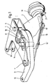
- Fig. 1 is a perspective and partly cut-away view of a disc brake caliper according to the invention
- Fig. 2 is a top view of the same caliper with associated brake pads cooperating with a brake disc
- Fig. 3 is a side view of the same caliper to a somewhat reduced scale with a brake pad holder and with suspension means.
- a disc brake caliper includes as main parts a generally U-shaped base frame 1, a bracket 2 attached to the base frame, and a brake lever 3 pivotally connected to the base frame by means of a pivot 4.
- This pivot 4 in the form of a screw joint also attaches the bracket 2 to the base frame 1 together with a screw joint 5.
- This caliper is intended for suspension from a rail vehicle underframe or bogie (for example by means described below and shown in Fig. 3) in the vicinity of a brake disc 6, which is mounted on a wheel axle of the vehicle in a way known per se. With minor modifications of the caliper it may quite as well be intended for cooperation with wheel-mounted brake discs.
- the free end portions of the base frame 1 and the brake lever 3, respectively, are provided with a pad holder 7 having a replaceable brake pad 8.
- the two pad holders 7 are pivotally mounted in holes 9 in the base frame 1 and in a hole 10 in the brake lever 3.
- the pad holder 7 at the base frame 1 may be fixedly attached thereto.
- each pad holder 7 is provided with a suspension link 11 (Fig. 3), whereas a central suspension bracket 12 is movably attached to an attachment 13 held to the base frame 1 by means of the screw joints 4 and 5.
- a suspension link 11 Fig. 3
- a central suspension bracket 12 is movably attached to an attachment 13 held to the base frame 1 by means of the screw joints 4 and 5.
- the base frame 1 is provided with a substantially centrally located pivot shaft 14, which is journalled in the two plates of the U-shaped base frame 1 and has a spined end extending out from the lower side of the base frame past the bracket 2.
- an automatic slack adjuster 15 which is well known in the automotive brake art and is normally used as a brake force-transmitting and slack adjusting lever in an S-cam drum brake system for heavy road vehicles, such as trucks and buses.
- the slack adjuster can be defined as being of the rotary, lever type, as the slack adjusting function results in a small rotary motion of a splined worm wheel of the adjuster and thus in this case of the pivot shaft 14.
- a pneumatic brake cylinder 16 is attached to a reinforcing flange 2' of the bracket 2, and its outgoing push rod 16' is connected to the end of the slack adjuster 15, as can be seen in Fig. 3.
- the pivot shaft 14 is provided with a small fixed arm or radial projection 17 between the two plates of the base frame 1.
- This projection 17 extends towards the brake disc 6 in the initial position with new brake pads 8 in the caliper.
- the projection 17 may have performed a turning or rotation of 90° in the clockwise direction, as viewed in Fig. 2, due to the slack adjusting function of the slack adjuster 15.
- the brake lever 3 extends past and partly around the pivot shaft 14 and is connected to the radial projection 17 by means of connecting links 18.
- the ratio between the effective lengths of the slack adjuster 15 and the radial projection 17 multiplied by the ratio between the effective lengths of the two arms of the brake lever 3 is the total ratio or leverage in the shown caliper. This total ratio may be considerable and is in the order of 4.5 with the shown geometry, whereas a direct connection of the brake lever 3 to the piston rod 16' of the brake cylinder 16 would have given a ratio in the order of 1.5 with otherwise unchanged geometry.
- the original position of the radial projection 17 may be restored by manual rotation of a reset nut 15' on the slack adjuster 15.
- the used automatic slack adjuster 15 is manufactured at comparatively low cost and may be regarded as a well functioning machine element, it may be replaced by a manual slack adjuster of the type more commonly used earlier in the automotive industry or even by a simple arm, if the slack adjusting function is not required at all.
- Another modification would be to alter the means for transmitting the forces between the radial projection 17 and the brake lever 3.
- a cam arrangement replacing the connecting links 18 would be feasible, although it would be difficult to obviate excessive leverage fluctuations.
- the pivot shaft 14 is said to be "centrally located” but may - as a further modification - have another location in the base frame 1, which also instead of being U-shaped can consist of two connected plates or have a similar design.
Landscapes
- Engineering & Computer Science (AREA)
- Mechanical Engineering (AREA)
- General Engineering & Computer Science (AREA)
- Braking Arrangements (AREA)
Applications Claiming Priority (2)
| Application Number | Priority Date | Filing Date | Title |
|---|---|---|---|
| SE8202163A SE8202163L (sv) | 1982-04-05 | 1982-04-05 | Skivbromstang for ett jernvegsfordon |
| SE8202163 | 1982-04-05 |
Publications (2)
| Publication Number | Publication Date |
|---|---|
| EP0091151A1 EP0091151A1 (en) | 1983-10-12 |
| EP0091151B1 true EP0091151B1 (en) | 1986-06-25 |
Family
ID=20346468
Family Applications (1)
| Application Number | Title | Priority Date | Filing Date |
|---|---|---|---|
| EP83200408A Expired EP0091151B1 (en) | 1982-04-05 | 1983-03-24 | A rail vehicle disc brake caliper |
Country Status (8)
| Country | Link |
|---|---|
| US (1) | US4497392A (pt) |
| EP (1) | EP0091151B1 (pt) |
| JP (1) | JPS58184327A (pt) |
| AU (1) | AU1309183A (pt) |
| BR (1) | BR8301716A (pt) |
| CA (1) | CA1197794A (pt) |
| DE (1) | DE3364251D1 (pt) |
| SE (1) | SE8202163L (pt) |
Families Citing this family (10)
| Publication number | Priority date | Publication date | Assignee | Title |
|---|---|---|---|---|
| GB8815374D0 (en) * | 1988-06-28 | 1988-08-03 | Westinghouse Brake & Signal | Brake equipment |
| DE4431353C1 (de) * | 1994-09-02 | 1996-03-28 | Knorr Bremse Systeme | Bremszangeneinheit für Scheibenbremsen von Fahrzeugen, insbesondere Schienenfahrzeugen |
| DE602004015613D1 (de) * | 2004-10-25 | 2008-09-18 | Meritor Heavy Vehicle Braking | Bremshebelanordnung für Motorfahrzeug und Verfahren zur Montage |
| US20090071768A1 (en) * | 2004-11-17 | 2009-03-19 | Brian Anthony Paulsen | Mechanical Disc Braking Assembly |
| JP4804791B2 (ja) * | 2005-05-10 | 2011-11-02 | ナブテスコ株式会社 | 鉄道車両用ディスクブレーキ装置 |
| JP4939441B2 (ja) * | 2008-01-04 | 2012-05-23 | 曙ブレーキ工業株式会社 | ブレーキアーム支持構造 |
| JP5880003B2 (ja) * | 2011-12-14 | 2016-03-08 | 新日鐵住金株式会社 | 鉄道車両用キャリパブレーキ装置 |
| SE537115C2 (sv) * | 2012-07-05 | 2015-01-20 | Scania Cv Ab | Lagerkonsolkonfiguration för trumbroms och metod för montering av en lagerkonsolkonfiguration |
| WO2014103883A1 (ja) | 2012-12-26 | 2014-07-03 | ナブテスコ株式会社 | 鉄道車両用ディスクブレーキ装置 |
| DE102013114525A1 (de) * | 2013-12-19 | 2015-06-25 | Pintsch Bubenzer Gmbh | Anschlaganordnung und Bremseinrichtung mit einer solchen |
Family Cites Families (8)
| Publication number | Priority date | Publication date | Assignee | Title |
|---|---|---|---|---|
| US3189128A (en) * | 1962-09-07 | 1965-06-15 | Budd Co | Disc brake installation |
| GB1108940A (en) * | 1964-08-15 | 1968-04-10 | Girling Ltd | Disc brake |
| CH489386A (de) * | 1969-03-17 | 1970-04-30 | Bromsregulator Svenska Ab | Bremsaggregat an einem Schienenfahrzeug |
| US3628635A (en) * | 1969-05-10 | 1971-12-21 | Kiyokazu Yoshigai | Bicycle brake |
| DE1960066A1 (de) * | 1969-11-29 | 1971-06-03 | Knorr Bremse Gmbh | Scheibenbremsbetaetigungsvorrichtung |
| US4022300A (en) * | 1976-08-19 | 1977-05-10 | Dayton-Walther Corporation | Mechanical disc brake |
| GB1597631A (en) * | 1978-01-06 | 1981-09-09 | Westinghouse Brake & Signal | Slack adjuster mechanism |
| SE435262B (sv) * | 1980-08-27 | 1984-09-17 | Sab Ind Ab | Skivbromsarrangemang for ett jernvegsfordon |
-
1982
- 1982-04-05 SE SE8202163A patent/SE8202163L/ not_active Application Discontinuation
-
1983
- 1983-03-24 DE DE8383200408T patent/DE3364251D1/de not_active Expired
- 1983-03-24 EP EP83200408A patent/EP0091151B1/en not_active Expired
- 1983-03-29 US US06/480,108 patent/US4497392A/en not_active Expired - Fee Related
- 1983-03-31 CA CA000425083A patent/CA1197794A/en not_active Expired
- 1983-03-31 AU AU13091/83A patent/AU1309183A/en not_active Abandoned
- 1983-04-04 BR BR8301716A patent/BR8301716A/pt not_active IP Right Cessation
- 1983-04-05 JP JP58058826A patent/JPS58184327A/ja active Pending
Also Published As
| Publication number | Publication date |
|---|---|
| JPS58184327A (ja) | 1983-10-27 |
| DE3364251D1 (en) | 1986-07-31 |
| SE8202163L (sv) | 1983-10-06 |
| EP0091151A1 (en) | 1983-10-12 |
| CA1197794A (en) | 1985-12-10 |
| US4497392A (en) | 1985-02-05 |
| BR8301716A (pt) | 1983-12-13 |
| AU1309183A (en) | 1983-10-13 |
Similar Documents
| Publication | Publication Date | Title |
|---|---|---|
| US5069312A (en) | Handbrake for single-cylinder truck-mounted railway car brake | |
| EP0046619B1 (en) | A rail vehicle disc brake arrangement | |
| AU600538B2 (en) | Single-cylinder, truck-mounted brake assembly | |
| EP0091151B1 (en) | A rail vehicle disc brake caliper | |
| CA1270211A (en) | Single-cylinder truck-mounted brake assembly | |
| US4034858A (en) | Support structure for a disc brake caliper | |
| US4491340A (en) | Vehicle wheel axle and brake mounting assembly | |
| US8006812B2 (en) | Disc brake caliper | |
| US3917032A (en) | Single mount and guide pin for a caliper of a disc brake assembly | |
| JPH10505038A (ja) | 車両、特にレール車両のディスクブレーキのためのブレーキキャリパユニット | |
| EP1827944A1 (en) | Disk brake arranged tmx | |
| JP2002535565A (ja) | ハブ支持体 | |
| US5205383A (en) | Reaction force type disk brake | |
| CA2195063C (en) | Brake bracket assembly | |
| JPS62255627A (ja) | 円板ブレ−キ | |
| US4511019A (en) | Spot-type disc brake, in particular for automotive vehicles | |
| EP0018050B2 (en) | A railway vehicle brake block holder | |
| EP0025290B1 (en) | Railway brakes | |
| JP4718422B2 (ja) | ディスクブレーキ | |
| US4527666A (en) | Rail vehicle disc brake arrangement | |
| CA2156881C (en) | Steer axle brake assembly | |
| US3696892A (en) | Brake head-centering device for railway brake apparatus | |
| JPH05147511A (ja) | ブレーキブロツクホルダを備える車両ブレーキ作動器 | |
| EP0077586B1 (en) | A railway vehicle brake block holder | |
| JPH106990A (ja) | 鉄道車両用台車のブレーキ装置 |
Legal Events
| Date | Code | Title | Description |
|---|---|---|---|
| PUAI | Public reference made under article 153(3) epc to a published international application that has entered the european phase |
Free format text: ORIGINAL CODE: 0009012 |
|
| AK | Designated contracting states |
Designated state(s): DE FR GB IT |
|
| 17P | Request for examination filed |
Effective date: 19831121 |
|
| ITF | It: translation for a ep patent filed |
Owner name: CALVANI SALVI E VERONELLI S.R.L. |
|
| GRAA | (expected) grant |
Free format text: ORIGINAL CODE: 0009210 |
|
| STAA | Information on the status of an ep patent application or granted ep patent |
Free format text: STATUS: THE PATENT HAS BEEN GRANTED |
|
| AK | Designated contracting states |
Kind code of ref document: B1 Designated state(s): DE FR GB IT |
|
| REF | Corresponds to: |
Ref document number: 3364251 Country of ref document: DE Date of ref document: 19860731 |
|
| ET | Fr: translation filed | ||
| PLBE | No opposition filed within time limit |
Free format text: ORIGINAL CODE: 0009261 |
|
| 26N | No opposition filed | ||
| PGFP | Annual fee paid to national office [announced via postgrant information from national office to epo] |
Ref country code: FR Payment date: 19900223 Year of fee payment: 8 |
|
| ITTA | It: last paid annual fee | ||
| PGFP | Annual fee paid to national office [announced via postgrant information from national office to epo] |
Ref country code: GB Payment date: 19900331 Year of fee payment: 8 |
|
| PGFP | Annual fee paid to national office [announced via postgrant information from national office to epo] |
Ref country code: DE Payment date: 19900515 Year of fee payment: 8 |
|
| PG25 | Lapsed in a contracting state [announced via postgrant information from national office to epo] |
Ref country code: GB Effective date: 19910324 |
|
| ITPR | It: changes in ownership of a european patent |
Owner name: CESSIONE;SAB WABCO HOLDINGS BV |
|
| REG | Reference to a national code |
Ref country code: FR Ref legal event code: TP Ref country code: FR Ref legal event code: CD |
|
| GBPC | Gb: european patent ceased through non-payment of renewal fee | ||
| PG25 | Lapsed in a contracting state [announced via postgrant information from national office to epo] |
Ref country code: FR Effective date: 19911129 |
|
| PG25 | Lapsed in a contracting state [announced via postgrant information from national office to epo] |
Ref country code: DE Effective date: 19920101 |
|
| REG | Reference to a national code |
Ref country code: FR Ref legal event code: ST |