EP0090358B1 - Pile à combustible - Google Patents
Pile à combustible Download PDFInfo
- Publication number
- EP0090358B1 EP0090358B1 EP83102946A EP83102946A EP0090358B1 EP 0090358 B1 EP0090358 B1 EP 0090358B1 EP 83102946 A EP83102946 A EP 83102946A EP 83102946 A EP83102946 A EP 83102946A EP 0090358 B1 EP0090358 B1 EP 0090358B1
- Authority
- EP
- European Patent Office
- Prior art keywords
- electrode
- noble metal
- fuel cell
- particles
- water
- Prior art date
- Legal status (The legal status is an assumption and is not a legal conclusion. Google has not performed a legal analysis and makes no representation as to the accuracy of the status listed.)
- Expired
Links
Images


Classifications
-
- H—ELECTRICITY
- H01—ELECTRIC ELEMENTS
- H01M—PROCESSES OR MEANS, e.g. BATTERIES, FOR THE DIRECT CONVERSION OF CHEMICAL ENERGY INTO ELECTRICAL ENERGY
- H01M4/00—Electrodes
- H01M4/86—Inert electrodes with catalytic activity, e.g. for fuel cells
- H01M4/88—Processes of manufacture
- H01M4/8803—Supports for the deposition of the catalytic active composition
- H01M4/881—Electrolytic membranes
-
- H—ELECTRICITY
- H01—ELECTRIC ELEMENTS
- H01M—PROCESSES OR MEANS, e.g. BATTERIES, FOR THE DIRECT CONVERSION OF CHEMICAL ENERGY INTO ELECTRICAL ENERGY
- H01M4/00—Electrodes
- H01M4/86—Inert electrodes with catalytic activity, e.g. for fuel cells
- H01M4/8663—Selection of inactive substances as ingredients for catalytic active masses, e.g. binders, fillers
- H01M4/8668—Binders
-
- H—ELECTRICITY
- H01—ELECTRIC ELEMENTS
- H01M—PROCESSES OR MEANS, e.g. BATTERIES, FOR THE DIRECT CONVERSION OF CHEMICAL ENERGY INTO ELECTRICAL ENERGY
- H01M4/00—Electrodes
- H01M4/86—Inert electrodes with catalytic activity, e.g. for fuel cells
- H01M4/88—Processes of manufacture
- H01M4/8825—Methods for deposition of the catalytic active composition
- H01M4/8842—Coating using a catalyst salt precursor in solution followed by evaporation and reduction of the precursor
-
- H—ELECTRICITY
- H01—ELECTRIC ELEMENTS
- H01M—PROCESSES OR MEANS, e.g. BATTERIES, FOR THE DIRECT CONVERSION OF CHEMICAL ENERGY INTO ELECTRICAL ENERGY
- H01M4/00—Electrodes
- H01M4/86—Inert electrodes with catalytic activity, e.g. for fuel cells
- H01M4/90—Selection of catalytic material
- H01M4/92—Metals of platinum group
-
- H—ELECTRICITY
- H01—ELECTRIC ELEMENTS
- H01M—PROCESSES OR MEANS, e.g. BATTERIES, FOR THE DIRECT CONVERSION OF CHEMICAL ENERGY INTO ELECTRICAL ENERGY
- H01M8/00—Fuel cells; Manufacture thereof
- H01M8/02—Details
- H01M8/0289—Means for holding the electrolyte
-
- H—ELECTRICITY
- H01—ELECTRIC ELEMENTS
- H01M—PROCESSES OR MEANS, e.g. BATTERIES, FOR THE DIRECT CONVERSION OF CHEMICAL ENERGY INTO ELECTRICAL ENERGY
- H01M8/00—Fuel cells; Manufacture thereof
- H01M8/08—Fuel cells with aqueous electrolytes
-
- H—ELECTRICITY
- H01—ELECTRIC ELEMENTS
- H01M—PROCESSES OR MEANS, e.g. BATTERIES, FOR THE DIRECT CONVERSION OF CHEMICAL ENERGY INTO ELECTRICAL ENERGY
- H01M8/00—Fuel cells; Manufacture thereof
- H01M8/10—Fuel cells with solid electrolytes
- H01M8/1009—Fuel cells with solid electrolytes with one of the reactants being liquid, solid or liquid-charged
-
- H—ELECTRICITY
- H01—ELECTRIC ELEMENTS
- H01M—PROCESSES OR MEANS, e.g. BATTERIES, FOR THE DIRECT CONVERSION OF CHEMICAL ENERGY INTO ELECTRICAL ENERGY
- H01M8/00—Fuel cells; Manufacture thereof
- H01M8/10—Fuel cells with solid electrolytes
- H01M8/1004—Fuel cells with solid electrolytes characterised by membrane-electrode assemblies [MEA]
-
- Y—GENERAL TAGGING OF NEW TECHNOLOGICAL DEVELOPMENTS; GENERAL TAGGING OF CROSS-SECTIONAL TECHNOLOGIES SPANNING OVER SEVERAL SECTIONS OF THE IPC; TECHNICAL SUBJECTS COVERED BY FORMER USPC CROSS-REFERENCE ART COLLECTIONS [XRACs] AND DIGESTS
- Y02—TECHNOLOGIES OR APPLICATIONS FOR MITIGATION OR ADAPTATION AGAINST CLIMATE CHANGE
- Y02E—REDUCTION OF GREENHOUSE GAS [GHG] EMISSIONS, RELATED TO ENERGY GENERATION, TRANSMISSION OR DISTRIBUTION
- Y02E60/00—Enabling technologies; Technologies with a potential or indirect contribution to GHG emissions mitigation
- Y02E60/30—Hydrogen technology
- Y02E60/50—Fuel cells
-
- Y—GENERAL TAGGING OF NEW TECHNOLOGICAL DEVELOPMENTS; GENERAL TAGGING OF CROSS-SECTIONAL TECHNOLOGIES SPANNING OVER SEVERAL SECTIONS OF THE IPC; TECHNICAL SUBJECTS COVERED BY FORMER USPC CROSS-REFERENCE ART COLLECTIONS [XRACs] AND DIGESTS
- Y02—TECHNOLOGIES OR APPLICATIONS FOR MITIGATION OR ADAPTATION AGAINST CLIMATE CHANGE
- Y02P—CLIMATE CHANGE MITIGATION TECHNOLOGIES IN THE PRODUCTION OR PROCESSING OF GOODS
- Y02P70/00—Climate change mitigation technologies in the production process for final industrial or consumer products
- Y02P70/50—Manufacturing or production processes characterised by the final manufactured product
Definitions
- This invention relates to a fuel cell using methanol as a fuel, and more particularly to an improvement of a fuel cell using an electrolyte ion exchange membrane.
- a fuel cell using an electrolyte ion exchange membrane is disclosed, for example, in Japanese Patent Application Kokai (Laid-open) No. 56-138874, where catalyst particles are fixed to the surface of an ion exchange membrane, and the ion exchange membrane and an electrode are integrated into one body.
- the procedures for fixing catalyst particles to the surface of an ion exchange membrane are described in detail therein together with the prior art ones. According to one of the procedures disclosed therein, the surface of an ion exchange membrane is roughened and catalyst particles are fixed to ther roughened surface, where a binder such as polytetrafluoroethylene, etc. is required when the amount of catalyst particles to be fixed exceeds about 2 mg/cm 2 .
- an electrode material comprising metal or alloy powder and a resin binder is distributed onto the surface of an ion exchange resin membrane and integrated with the ion exchange resin membrane at an elevated temperature under pressure.
- All of the integrated electrodes disclosed in Japanese Patent Application Kokai (Laid-open) No. 56-138874 are hydrophilic on the electrode surfaces, and even if polytetrafluoroethylene having a water-repellent property is used as a binder, the electrode surfaces are substantially hydrophilic and not water-repellent.
- the integrated electrode having catalyst particles integrated with an ion exchange membrane so far proposed is hydrophilic, and is not suitable for an oxidizer electrode (or cathode or air electrode) of a fuel cell using methanol as fuel, because, in the case of using such an oxidizer electrode, a three-phase boundary is hardly obtainable among catalyst particles (solid), a fuel (liquid) and an oxidizer (gas) with the result of a poor cell performance.
- An object of the present invention is to provide a fuel cell with an integrated electrode having catalyst particles fixed to an ion exchange membrane and using methanol as a fuel, where the three-phase boundary is readily obtainable with an oxidizer electrode.
- Another object of the present invention is to provide a methanol fuel cell with an oxidizer electrode having water-repellent particles and catalyst particles finely distributed by the presence of the water-repellent particles.
- water-repellent particles and noble metal particles having a catalytic action are supported on one side of an ion exchange membrane to provide an oxidizer electrode, whereas noble metal particles having a catalytic action are supported on the other side thereof to provide a fuel electrode. That is, an oxidizer electrode and a fuel electrode are integrally formed on one side and another side, respectively, of an ion exchange membrane.
- the air electrode of methanol fuel cell must be water-repellent and have a three-phase boundary, i.e. an interface of liquid phase-solid phase-gas phase, when the relevant reaction is taken into account.
- the fuel electrode (sometimes called an anode or a methanol electrode) must be hydrophilic.
- a methanol fuel cell having an integrated electrode which comprises an oxidizer electrode having a water-repellent property on one side of an electrolyte ion - exchange membrane, and a fuel electrode having a hydrophilic property on the other side thereof, while noble metal catalyst particles are fixed to both sides thereof, has a considerably distinguished cell performance over the fuel cell having a hydrophilic oxidizer electrode and fuel electrode integrated with an ion exchange membrane.
- the difference between these cells is larger than that in cell performance between a methanol fuel cell having integrated hydrophilic electrodes and a methanol fuel cell having unintegrated electrodes and ion exchange membrane.
- the distinguished cell performance of the present fuel cell can tie due to a combination of the oxidizer electrode having a water-repellent property with the integration of the electrodes with an ion exchange membrane.
- an oxidizer electrode contains water-repellent particles and is made water-repellent by the water-repellent particles.
- the water-repellent particles can include polytetrafluoroethylene, styrene-divinylbenzene co- polymer, polyethylene and fluorocarbon, etc. It is necessary that the water-repellent particles exist at least on the surface of an oxidizer electrode. The water-repellent particles can be distributed throughout the entire oxidizer electrode. It is desirable that the water-repellent particles have a particle size of 0.1-1 pm. If the particle size is too small, the water-repellent particles are liable to coagulate, whereas, if too large, the water repellency becomes too strong to form the three-phase boundary.
- noble metal particles As catalyst particles for both oxidizer electrode and fuel electrode, and it is desirable to use at least one of platinum, ruthenium, palladium and rhodium of the periodic table, Group VIII as the noble metal particles.
- platinum is desirable as the catalyst particles for an oxidizer electrode, and a mixture of platinum and ruthenium is desirable as the catalyst particle for a fuel electrode.
- binders In integral formation of an oxidizer electrode or a fuel electrode on the surface of an ion exchange membrane, various binders can be used, for example, polytetrafluoroethylene.
- the most appropriate procedure for integral formation of an oxidizer electrode on the surface of an ion exchange membrane is a composite coating procedure, and likewise the most preferable procedure for integration of an oxidizer electrode on the surface of an ion exchange membrane is a chemical plating procedure.
- a binder By utilizing these plating procedures, use of a binder can be omitted, and furthermore noble metal particles can be made to exist in a very fine state.
- Composite coating can be carried out by contacting one side of an ion exchange membrane with a solution containing noble metal and water-repellent particles and contacting the other side with a reducing agent solution, thereby conducting chemical plating.
- the noble metal particles and the water-repellent particles are supported on the surface of the ion exchange membrane on the side contacted with the solution containing the noble metal and the water-repellent particles.
- the ion exchange membrane is washed with water and d ried, whereby the ion exchange membrane integrated with the oxidizer electrode can be obtained.
- the noble metal particles can be distributed on the surface of the ion exchange membrane in a very fine and uniform state.
- the resulting platinum particles have particle sizes of 7 ⁇ 0.5 nm, which are considerably smaller than those obtained by chemical plating with a chloroplatinic acid solution containing no water-repellent particles, i.e. 9-12 nm.
- Integrated formation of a fuel electrode on the other side of the ion exchange membrane can be also carried out by substantially same chemical plating as in formation of an oxidizer electrode. In this case, it is not necessary to add water-repellent particles to the solution containing noble metal, or rather such addition must be avoided. Except for this difference, the fuel electrode can be formed by chemical plating in quite same manner as in forming the oxidizer electrode.
- the fuel electrode thus formed can usually have noble metal particles having particle sizes of 9-12 nm. In most cases, the noble metal particles supported on the surface of an ion exchange membrane by composite coating have particle sizes of 6 ⁇ 8 nm.
- platinum particles are used as noble metal, a further difference appears in behavior of platinum particles between the case of supporting it on an ion exchange membrane by dispersion plating and the case by chemical plating with no addition of the water-repellent particles. That is, platinum black is formed when the water-repellent particles are used, whereas platinum particles have a metallic luster when no such water-repellent particles are used.
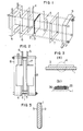
- a methanol fuel cell has a methanol electrode (fuel electrode) 2 and an air electrode (oxidizer electrode) 3 at one side and another side, respectively, of an ion exchange membrane 1 as an electrolyte.
- the ion exchange membrane 1, the methanol electrode 2 and the air electrode 3 are integrated into one body, and thus there is no contact resistance between the electrodes 2 and 3 and the ion exchange membrane 1 with the result of prevention of cell performance from lowering due to the contact resistance between the electrodes and the ion exchange membrane. Furthermore, the present fuel cell has no such problems that a carbon dioxide gas as a reaction product at the methanol electrode 2 is retained between the methanol electrode 2 and the ion exchange membrane 1 to disturb the electrode reaction or to increase the resistance at the interfaces.
- Numeral 4 is a current collector at the methanol electrode, 5 a current collector at the air electrode, 6 a sealant for methanol fuel chamber, 7 a sealant for air chamber, 8 a methanol fuel chamber, and 9 an air chamber. It is desirable to use a strongly acidic ion exchange membrane as the ion exchange membrane.
- Electricity is generated in a methanol fuel cell in the following manner.
- a 3 M H 2 S0 4 solution is mixed with methanol to make the concentration of 1 mole/I, and the resulting solution is introduced into the methanol fuel chamber 8, while air or oxygen is introduced into the air chamber 9 and keeping the cell temperature at 50°-60°C, whereby an electric current can be immediately withdrawn therefrom into an outer circuit.
- methanol is oxidized at the methanol electrode 2 to produce carbon dioxide gas, hydrogen ions and electrons.
- the thus formed hydrogen ions migrate through the strongly acidic ion exchange membrane 1 and react with oxygen and electrons from the outer circuit at the air electrode 3 to form water.
- An ion exchange membrane 1 of styrene-divinylbenzene co-polymer system having sulfonate groups was used.
- a reducing agent solution was provided in a chamber in contact with the membrane 1 at one side and a platinum catalyst solution in a chamber in contact with the other side of the membrane 1, and the catalyst was fixed to the membrane 1 by chemical plating.
- the reducing agent solution was a 5 mol.% hydrazine solution ⁇
- the catalyst solution was a 0.5 mol.% chloroplatinic acid solution containing 1.5 wt.% of water-repellent particles (Polyflon Dispersion D-1, made by Daikin Kogyo K.K., Japan).
- the chemical plating was carried out at room temperature for 2 hours, and the membrane was washed with water and left standing at room temperature until the electrode catalyst on the membrane 1 was dried.
- the thus prepared electrode catalyst formed an air electrode 3 as tightly fixed to the ion exchange membrane 1 together with the water-repellent particles, as shown in Fig. 3(a), and the catalyst surface had a water-repellent property.
- platinum electrode catalyst 35 and water-repellent particles 36 were supported on the ion exchange membrane 1, where the platinum electrode catalyst 35 turned platinum black, which means that a kind of composite coating was carried out.
- X-ray diffraction of platinum electrode catalyst 35 as the catalyst revealed that the primary particles of the catalyst had a particle size of 77A, the amount of supported platinum was 5 mg/cm 2 , and the water-repellent particles had particle sizes of 0.2-0.4 pm.
- the thus obtained ion exchange membrane 1 integrated with the air electrode 3 was subjected to single electrode measurement to determine relationship between a current density and an air electrode potential.
- the results are shown by curve a in Fig. 4, where an open circuit potential was 0.99 V and an air electrode potential at the current density of 5 mA/cm 2 was 0.72 V.
- a 0.5 mol.% chloroplatinic acid solution was used as a catalyst solution, and an electrode catalyst containing no water-repellent particles was supported on one side of the ion exchange membrane 1 under the same conditions as in Test Example 1.
- Platinum supported as the electrode catalyst had a metallic luster and was readily wettable with water.
- X-ray diffraction of the thus obtained platinum revealed that the primary particles of the catalyst had a particle size of 9.2 nm, and the amount of supported platinum was 5 mg/ cm 2.
- the thus obtained membrane was subjected to single electrode measurement as an air electrode, and the results are shown by curve 6 in Fig. 4, where an open circuit voltage was 0.91 V, but the air electrode potential was rapidly lowered by outputting a current, and was 0.4 V at the current density of 0.25 mA/cm 2 .
- Test Example 1 Comparison in performance between Test Examples 1 and 2 revealed that according to Test Example 1 of using an air electrode 3 having both water-repellent particles 36 and platinum electrode catalyst 35 on one side of the ion exchange membrane 1 had a remarkably improved performance as an air electrode for a methanol fuel cell. This seems due to the fact that a three-phase boundary was readily formed.
- a mixture of 0.5 mol.% of chloroplatinic acid and 0.5 mol.% of ruthenium chloride was used as a catalyst solution, and an electrode catalyst was supported on other side of : ion exchange membrane 1 under the same conditions as in Test Example 1 to obtain a methanol electrode 2.
- a platinum electrode catalyst containing no ruthenium was supported on other side of ion exchange membrane 1 in the same manner as in Test Example 2 to obtain a methanol electrode, and the thus obtained membrane was subjected to single electrode measurement.
- the results are shown by curve d in Fig. 6, where an open circuit voltage was 0.2 9 V, and a methanol electrode potential at the current density of 2.5 mA/cm 2 was 0.7 V.
- Water-repellent particles and platinum electrode catalyst were supported on one side of ion exchange membrane in the same manner as in Test Example 1 to form an air electrode 3 and then an electrode catalyst consisting of two components, platinum and ruthenium, was supported on the other side of the ion exchange membrane 1 in the same manner as in Test Example 3 to obtain a methanol electrode 2.
- the ion exchange membrane 1 integrated with the air electrode 3 on one side and with the methanol electrode 2 on the other side, as shown in Fig. 5 was assembled into a methanol fuel cell having the structure shown in Fig. 1 and subjected to cell performance measurement. The results are shown in Fig.
- Fig. 7 is a diagram showing relationship between a current density and a cell voltage, where an open circuit voltage was 0.83 V, and a cell voltage at the current density of 5 mA/cm 2 was 0.22 V. It has been found that a good cell performance was obtained.
- the same chloroplatinic acid solution as used in Test Example 1 was reduced with hydrazine to obtain platinum black, and the platinum black was mixed with water-repellent particles (Polyflon Dispersion D-1, made by Daikin Kogyo K.K., Japan) to obtain an air electrode catalyst.
- the catalyst contained 10 wt.% of the water-repellent particles as a water repellent and a binder.
- the catalyst was applied to a tantalum wire netting as a current collector at a platinum rate of 5 mg/cm 2 to obtain an air electrode.
- the same catalyst solution as used in Test Example 3 was reduced with hydrazine and mixed with the said water-repellent particles to obtain a methanol electrode catalyst, which contained 5 wt.% of the water-repellent particles as a binder.
- the thus obtained catalyst was applied to a tantalum wire netting at a platinum rate of 5 mg/cm 2 to obtain a methanol electrode.
- the thus obtained two electrodes were placed on one side and the other side, respectively, of an ion exchange resin membrane of styrene-divinylbenzene co-polymer having sulfonate groups and assembled into a fuel cell having the structure shown in fig. 2 and subjected to cell performance measurement.
- the results are shown in Fig. 8.
- the cell had an open circuit voltage of 0.75 V and a cell voltage of 0.14 V at the current density of 5 mA/cm 2 .
- an integrated air electrode 4 is provided by supporting water-repellent particles 36 and platinum electrode catalyst 35 on one side of an ion exchange membrane 5, whereby a three-phase boundary can be readily formed and a performance of air electrode for a methanol fuel cell can be greatly increased.
- an electrode catalyst consisting of two components, i.e. platinum and ruthenium, is supported on the other side of ion exchange membrane 1 to form an integrated methanol electrode 2. No clearance can be provided between the ion exchange membrane 1 and the electrodes 2 and 3, whereby the contact resistance can be considerably reduced.
- a cell assembling time can be reduced to above 1/5 of that required for assembling a fuel cell from separately'prepared air electrode, methanol electrode and ion exchange membrane.
- the contact resistance can be greatly reduced between the ion exchange membrane and the electrodes to improve the cell performance and also the assembling work.
Landscapes
- Chemical & Material Sciences (AREA)
- Chemical Kinetics & Catalysis (AREA)
- Electrochemistry (AREA)
- General Chemical & Material Sciences (AREA)
- Engineering & Computer Science (AREA)
- Manufacturing & Machinery (AREA)
- Life Sciences & Earth Sciences (AREA)
- Sustainable Development (AREA)
- Sustainable Energy (AREA)
- Materials Engineering (AREA)
- Inert Electrodes (AREA)
- Fuel Cell (AREA)
Claims (19)
Applications Claiming Priority (2)
| Application Number | Priority Date | Filing Date | Title |
|---|---|---|---|
| JP49804/82 | 1982-03-26 | ||
| JP57049804A JPS58165266A (ja) | 1982-03-26 | 1982-03-26 | 燃料電池 |
Publications (3)
| Publication Number | Publication Date |
|---|---|
| EP0090358A2 EP0090358A2 (fr) | 1983-10-05 |
| EP0090358A3 EP0090358A3 (en) | 1986-01-15 |
| EP0090358B1 true EP0090358B1 (fr) | 1988-07-06 |
Family
ID=12841324
Family Applications (1)
| Application Number | Title | Priority Date | Filing Date |
|---|---|---|---|
| EP83102946A Expired EP0090358B1 (fr) | 1982-03-26 | 1983-03-24 | Pile à combustible |
Country Status (4)
| Country | Link |
|---|---|
| US (1) | US4478917A (fr) |
| EP (1) | EP0090358B1 (fr) |
| JP (1) | JPS58165266A (fr) |
| DE (1) | DE3377318D1 (fr) |
Families Citing this family (60)
| Publication number | Priority date | Publication date | Assignee | Title |
|---|---|---|---|---|
| JPS60189174A (ja) * | 1984-03-07 | 1985-09-26 | Hitachi Ltd | 燃料電池 |
| DE3618840A1 (de) * | 1986-06-04 | 1987-12-10 | Basf Ag | Methanol/luft-brennstoffzellen |
| JPH0624635B2 (ja) * | 1987-05-19 | 1994-04-06 | ヤンマーディーゼル株式会社 | メタノール系燃料電池用の高活性触媒粉末とこれを用いた高活性電極の製造方法 |
| GB8724543D0 (en) * | 1987-10-20 | 1987-11-25 | Johnson Matthey Plc | Demonstrating & studying operation of fuel cell |
| US4769297A (en) * | 1987-11-16 | 1988-09-06 | International Fuel Cells Corporation | Solid polymer electrolyte fuel cell stack water management system |
| US5286580A (en) * | 1990-02-09 | 1994-02-15 | Osaka Gas Company Limited | Fuel electrode for solid electrolyte fuel cells and a method for manufacture of the electrode |
| AU8547391A (en) * | 1990-08-08 | 1992-03-02 | Physical Sciences, Inc. | Generation of electricity with fuel cell using alcohol fuel |
| US5132193A (en) * | 1990-08-08 | 1992-07-21 | Physical Sciences, Inc. | Generation of electricity with fuel cell using alcohol fuel |
| JPH06176771A (ja) * | 1991-09-13 | 1994-06-24 | Tanaka Kikinzoku Kogyo Kk | 燃料電池用イオン交換膜の構造 |
| US5773162A (en) * | 1993-10-12 | 1998-06-30 | California Institute Of Technology | Direct methanol feed fuel cell and system |
| US5599638A (en) | 1993-10-12 | 1997-02-04 | California Institute Of Technology | Aqueous liquid feed organic fuel cell using solid polymer electrolyte membrane |
| US6703150B2 (en) | 1993-10-12 | 2004-03-09 | California Institute Of Technology | Direct methanol feed fuel cell and system |
| EP1498973A1 (fr) * | 1994-10-18 | 2005-01-19 | The University Of Southern California | Cellule de combustible organique avec un additif d'électrocatalyseur |
| US5672439A (en) * | 1995-12-18 | 1997-09-30 | Ballard Power Systems, Inc. | Method and apparatus for reducing reactant crossover in an electrochemical fuel cell |
| US5789091C1 (en) * | 1996-11-19 | 2001-02-27 | Ballard Power Systems | Electrochemical fuel cell stack with compression bands |
| US5928806A (en) * | 1997-05-07 | 1999-07-27 | Olah; George A. | Recycling of carbon dioxide into methyl alcohol and related oxygenates for hydrocarbons |
| US5904740A (en) * | 1997-06-03 | 1999-05-18 | Motorola, Inc. | Fuel for liquid feed fuel cells |
| USRE39556E1 (en) * | 1997-11-20 | 2007-04-10 | Relion, Inc. | Fuel cell and method for controlling same |
| US6030718A (en) * | 1997-11-20 | 2000-02-29 | Avista Corporation | Proton exchange membrane fuel cell power system |
| US6096449A (en) * | 1997-11-20 | 2000-08-01 | Avista Labs | Fuel cell and method for controlling same |
| AU5865500A (en) * | 1999-02-26 | 2000-09-28 | Symyx Technologies, Inc. | Platinum-ruthenium-palladium alloys for use as a fuel cell catalyst |
| JP2003515236A (ja) | 1999-11-17 | 2003-04-22 | ネア・パワー・システムズ・インコーポレイテッド | シリコン基板および/またはゾルゲル法で誘導された担体構造を有する燃料電池 |
| US6492052B2 (en) * | 1999-12-17 | 2002-12-10 | The Regents Of The University Of California | Air breathing direct methanol fuel cell |
| US6458479B1 (en) * | 1999-12-17 | 2002-10-01 | The Regents Of The University Of California | Air breathing direct methanol fuel cell |
| CN1255894C (zh) * | 2000-01-18 | 2006-05-10 | 特拉维夫大学未来技术发展有限合伙公司 | 燃料 |
| US6468682B1 (en) | 2000-05-17 | 2002-10-22 | Avista Laboratories, Inc. | Ion exchange membrane fuel cell |
| US7326480B2 (en) | 2000-05-17 | 2008-02-05 | Relion, Inc. | Fuel cell power system and method of controlling a fuel cell power system |
| WO2001094450A2 (fr) | 2000-06-02 | 2001-12-13 | Sri International | Composition polymerique |
| AU2002220168A1 (en) * | 2000-11-14 | 2002-05-27 | The Regents Of The University Of California | Air breathing direct methanol fuel cell |
| US6632553B2 (en) * | 2001-03-27 | 2003-10-14 | Mti Microfuel Cells, Inc. | Methods and apparatuses for managing effluent products in a fuel cell system |
| US7316855B2 (en) | 2001-06-01 | 2008-01-08 | Polyfuel, Inc. | Fuel cell assembly for portable electronic device and interface, control, and regulator circuit for fuel cell powered electronic device |
| ATE400904T1 (de) | 2001-06-01 | 2008-07-15 | Polyfuel Inc | Austauschbare brennstoffpatrone, brennstoffzellenaggregat mit besagter brennstoffpatrone für tragbare elektronische geräte und entsprechendes gerät |
| JP3798276B2 (ja) * | 2001-08-16 | 2006-07-19 | 三菱電機株式会社 | 電気化学素子及び電気化学素子装置 |
| US6981877B2 (en) * | 2002-02-19 | 2006-01-03 | Mti Microfuel Cells Inc. | Simplified direct oxidation fuel cell system |
| US7049014B1 (en) | 2002-03-05 | 2006-05-23 | H Power Corporation | Direct secondary alcohol fuel cells |
| US7132188B2 (en) * | 2002-04-04 | 2006-11-07 | The Board Of Trustees Of The University Of Illinois | Fuel cells and fuel cell catalysts |
| US7785728B2 (en) * | 2002-04-04 | 2010-08-31 | The Board Of Trustees Of The University Of Illinois | Palladium-based electrocatalysts and fuel cells employing such electrocatalysts |
| US7740974B2 (en) | 2002-04-04 | 2010-06-22 | The Board Of Trustees Of The University Of Illinois | Formic acid fuel cells and catalysts |
| US7282282B2 (en) * | 2002-04-04 | 2007-10-16 | The Board Of Trustees Of The University Of Illinois | Organic fuel cells and fuel cell conducting sheets |
| US6908500B2 (en) * | 2002-04-08 | 2005-06-21 | Motorola, Inc. | System and method for controlling gas transport in a fuel cell |
| WO2004042839A2 (fr) | 2002-05-13 | 2004-05-21 | Polyfuel, Inc. | Copolymeres blocs conducteurs d'ions |
| US7354679B2 (en) | 2002-05-13 | 2008-04-08 | Polyfuel, Inc. | Ion conductive random copolymers |
| AU2003237849B2 (en) | 2002-05-13 | 2009-07-02 | Polyfuel, Inc. | Sulfonated copolymer |
| US7141322B2 (en) * | 2002-06-27 | 2006-11-28 | H Power Corporation | Alcohol fueled direct oxidation fuel cells |
| US20040062980A1 (en) * | 2002-09-30 | 2004-04-01 | Xiaoming Ren | Fluid management component for use in a fuel cell |
| US7282291B2 (en) | 2002-11-25 | 2007-10-16 | California Institute Of Technology | Water free proton conducting membranes based on poly-4-vinylpyridinebisulfate for fuel cells |
| US7407721B2 (en) * | 2003-04-15 | 2008-08-05 | Mti Microfuel Cells, Inc. | Direct oxidation fuel cell operating with direct feed of concentrated fuel under passive water management |
| US20040209133A1 (en) * | 2003-04-15 | 2004-10-21 | Hirsch Robert S. | Vapor feed fuel cell system with controllable fuel delivery |
| US20050170224A1 (en) * | 2003-04-15 | 2005-08-04 | Xiaoming Ren | Controlled direct liquid injection vapor feed for a DMFC |
| US7282293B2 (en) * | 2003-04-15 | 2007-10-16 | Mti Microfuel Cells Inc. | Passive water management techniques in direct methanol fuel cells |
| US7261966B2 (en) * | 2003-06-30 | 2007-08-28 | Zongshen Pem Power Systems Inc. | Apparatus and method for conducting fluid in a fuel cell and fuel cell employing same |
| US7306869B2 (en) * | 2003-12-02 | 2007-12-11 | Mti Microfuel Cells Inc. | Electrostatically actuated shutter and array for use in a direct oxidation fuel cell |
| US7323267B2 (en) * | 2004-10-07 | 2008-01-29 | Tekion, Inc. | Liquid feed fuel cell with nested sealing configuration |
| US20060292407A1 (en) * | 2004-12-15 | 2006-12-28 | Dominic Gervasio | Microfluidic fuel cell system and method for portable energy applications |
| GB0510119D0 (en) * | 2005-05-18 | 2005-06-22 | Johnson Matthey Plc | Polymer dispersion and electrocatalyst ink |
| JP5298405B2 (ja) | 2006-04-14 | 2013-09-25 | トヨタ自動車株式会社 | 燃料電池用膜電極接合体の製造方法 |
| US8465881B2 (en) * | 2007-12-20 | 2013-06-18 | Daimler Ag | Compression apparatus for fuel cell stack |
| DE102012014459B4 (de) | 2012-07-21 | 2018-02-08 | Forschungszentrum Jülich GmbH | Spannmittel für einen Brennstoffzellenstapel sowie Verfahren zum Verspannen eines Brennstoffzellenstapels |
| CN104084196B (zh) * | 2014-07-04 | 2016-01-27 | 哈尔滨工程大学 | 碳化的载Pd中空阴离子交换树脂微球H2O2电还原催化剂的制备方法 |
| CA2989410C (fr) | 2015-06-19 | 2023-10-24 | Ballard Power Systems Inc. | Assemblage de pile a combustible avec bandes de compression le long de surface planes de l'assemblage |
Citations (1)
| Publication number | Priority date | Publication date | Assignee | Title |
|---|---|---|---|---|
| US4272353A (en) * | 1980-02-29 | 1981-06-09 | General Electric Company | Method of making solid polymer electrolyte catalytic electrodes and electrodes made thereby |
Family Cites Families (13)
| Publication number | Priority date | Publication date | Assignee | Title |
|---|---|---|---|---|
| GB1143883A (fr) * | 1900-01-01 | |||
| US3134697A (en) * | 1959-11-03 | 1964-05-26 | Gen Electric | Fuel cell |
| GB1013703A (en) * | 1962-09-20 | 1965-12-22 | Commw Scient Ind Res Org | Improvements relating to fuel cells |
| US3423228A (en) * | 1965-03-22 | 1969-01-21 | Gen Electric | Deposition of catalytic noble metals |
| US3411954A (en) * | 1965-09-30 | 1968-11-19 | Leesona Corp | Method of making electrodes |
| US3668014A (en) * | 1968-06-10 | 1972-06-06 | Leesona Corp | Electrode and method of producing same |
| US3706602A (en) * | 1969-12-18 | 1972-12-19 | Hooker Chemical Corp | Fuel cell electrode structure utilizing capillary action |
| JPS54154048A (en) * | 1978-05-26 | 1979-12-04 | Hitachi Ltd | Disolving fuel battery |
| IT1212303B (it) * | 1978-07-10 | 1989-11-22 | Elche Ltd | Accumulatore redox. |
| US4215183A (en) * | 1979-01-02 | 1980-07-29 | General Electric Company | Wet proofed conductive current collector for the electrochemical cells |
| IT1130955B (it) * | 1980-03-11 | 1986-06-18 | Oronzio De Nora Impianti | Procedimento per la formazione di elettroci sulle superficie di membrane semipermeabili e sistemi elettrodo-membrana cosi' prodotti |
| JPS575266A (en) * | 1980-06-13 | 1982-01-12 | Hitachi Ltd | Manufacture of fuel electrode for fuel cell |
| US4390603A (en) * | 1981-06-30 | 1983-06-28 | Hitachi, Ltd. | Methanol fuel cell |
-
1982
- 1982-03-26 JP JP57049804A patent/JPS58165266A/ja active Granted
-
1983
- 1983-03-24 EP EP83102946A patent/EP0090358B1/fr not_active Expired
- 1983-03-24 DE DE8383102946T patent/DE3377318D1/de not_active Expired
- 1983-03-25 US US06/479,097 patent/US4478917A/en not_active Expired - Lifetime
Patent Citations (1)
| Publication number | Priority date | Publication date | Assignee | Title |
|---|---|---|---|---|
| US4272353A (en) * | 1980-02-29 | 1981-06-09 | General Electric Company | Method of making solid polymer electrolyte catalytic electrodes and electrodes made thereby |
Also Published As
| Publication number | Publication date |
|---|---|
| EP0090358A3 (en) | 1986-01-15 |
| JPH0413827B2 (fr) | 1992-03-10 |
| EP0090358A2 (fr) | 1983-10-05 |
| JPS58165266A (ja) | 1983-09-30 |
| US4478917A (en) | 1984-10-23 |
| DE3377318D1 (en) | 1988-08-11 |
Similar Documents
| Publication | Publication Date | Title |
|---|---|---|
| EP0090358B1 (fr) | Pile à combustible | |
| Oetjen et al. | Performance data of a proton exchange membrane fuel cell using H 2/CO as fuel gas | |
| US4248682A (en) | Carbon-cloth-based electrocatalytic gas diffusion electrodes, assembly and electrochemical cells comprising the same | |
| US4039409A (en) | Method for gas generation utilizing platinum metal electrocatalyst containing 5 to 60% ruthenium | |
| US4293396A (en) | Thin carbon-cloth-based electrocatalytic gas diffusion electrodes, and electrochemical cells comprising the same | |
| US5523177A (en) | Membrane-electrode assembly for a direct methanol fuel cell | |
| EP0253459A2 (fr) | Electrodes pour cellules électrochimiques à électrolyte d'oxydes solides | |
| US6828056B2 (en) | Electrode catalyst composition, electrode, and membrane electrode assembly for electrochemical cells | |
| CA2380976A1 (fr) | Structures anodiques de pile a combustible offrant une tolerance a l'inversion de tension | |
| RU2414772C2 (ru) | Структуры для газодиффузионных электродов | |
| EP2193565B1 (fr) | Système de pile à combustible | |
| JP2000012043A (ja) | 固体高分子電解質型燃料電池用電極触媒、並びに該触媒を用いた電極、電解質膜―電極接合体および固体高分子電解質型燃料電池 | |
| JPH09167622A (ja) | 電極触媒およびそれを用いた固体高分子型燃料電池 | |
| JP2836275B2 (ja) | 液体燃料電池用触媒の製造方法及びその電極の製造方法 | |
| EP0580072B1 (fr) | Electrode à diffusion gazeuse et réacteur électrochimique utilisant celle-ci | |
| US6864011B2 (en) | Fuel-cell electrode and method of manufacturing the fuel-cell electrode | |
| US20030031916A1 (en) | Fuel cell electrode | |
| JP7399582B2 (ja) | カソード触媒層、並びに、膜電極接合体及び燃料電池 | |
| JP2007141477A (ja) | 触媒材料及びそれを用いた電解質膜−電極接合体と燃料電池 | |
| US20030190517A1 (en) | Fuel cell | |
| JPH11135136A (ja) | 固体高分子電解質型燃料電池 | |
| US11901565B2 (en) | Fuel cell electrode catalyst, method for selecting the same, and fuel cell including the same | |
| JPH027399B2 (fr) | ||
| JP5535773B2 (ja) | 固体高分子型燃料電池用膜−電極構造体 | |
| JPH06231773A (ja) | 燃料電池 |
Legal Events
| Date | Code | Title | Description |
|---|---|---|---|
| PUAI | Public reference made under article 153(3) epc to a published international application that has entered the european phase |
Free format text: ORIGINAL CODE: 0009012 |
|
| AK | Designated contracting states |
Designated state(s): CH DE FR GB LI NL |
|
| 17P | Request for examination filed |
Effective date: 19841220 |
|
| PUAL | Search report despatched |
Free format text: ORIGINAL CODE: 0009013 |
|
| AK | Designated contracting states |
Designated state(s): CH DE FR GB LI NL |
|
| 17Q | First examination report despatched |
Effective date: 19870119 |
|
| GRAA | (expected) grant |
Free format text: ORIGINAL CODE: 0009210 |
|
| AK | Designated contracting states |
Kind code of ref document: B1 Designated state(s): CH DE FR GB LI NL |
|
| REF | Corresponds to: |
Ref document number: 3377318 Country of ref document: DE Date of ref document: 19880811 |
|
| ET | Fr: translation filed | ||
| PLBE | No opposition filed within time limit |
Free format text: ORIGINAL CODE: 0009261 |
|
| STAA | Information on the status of an ep patent application or granted ep patent |
Free format text: STATUS: NO OPPOSITION FILED WITHIN TIME LIMIT |
|
| 26N | No opposition filed | ||
| PGFP | Annual fee paid to national office [announced via postgrant information from national office to epo] |
Ref country code: FR Payment date: 19971217 Year of fee payment: 16 |
|
| PGFP | Annual fee paid to national office [announced via postgrant information from national office to epo] |
Ref country code: GB Payment date: 19971224 Year of fee payment: 16 |
|
| PGFP | Annual fee paid to national office [announced via postgrant information from national office to epo] |
Ref country code: NL Payment date: 19971231 Year of fee payment: 16 |
|
| PGFP | Annual fee paid to national office [announced via postgrant information from national office to epo] |
Ref country code: CH Payment date: 19980120 Year of fee payment: 16 |
|
| PGFP | Annual fee paid to national office [announced via postgrant information from national office to epo] |
Ref country code: DE Payment date: 19980331 Year of fee payment: 16 |
|
| PG25 | Lapsed in a contracting state [announced via postgrant information from national office to epo] |
Ref country code: GB Free format text: LAPSE BECAUSE OF NON-PAYMENT OF DUE FEES Effective date: 19990324 |
|
| PG25 | Lapsed in a contracting state [announced via postgrant information from national office to epo] |
Ref country code: LI Free format text: LAPSE BECAUSE OF NON-PAYMENT OF DUE FEES Effective date: 19990331 Ref country code: CH Free format text: LAPSE BECAUSE OF NON-PAYMENT OF DUE FEES Effective date: 19990331 |
|
| PG25 | Lapsed in a contracting state [announced via postgrant information from national office to epo] |
Ref country code: NL Free format text: LAPSE BECAUSE OF NON-PAYMENT OF DUE FEES Effective date: 19991001 |
|
| REG | Reference to a national code |
Ref country code: CH Ref legal event code: PL |
|
| GBPC | Gb: european patent ceased through non-payment of renewal fee |
Effective date: 19990324 |
|
| PG25 | Lapsed in a contracting state [announced via postgrant information from national office to epo] |
Ref country code: FR Free format text: LAPSE BECAUSE OF NON-PAYMENT OF DUE FEES Effective date: 19991130 |
|
| NLV4 | Nl: lapsed or anulled due to non-payment of the annual fee |
Effective date: 19991001 |
|
| REG | Reference to a national code |
Ref country code: FR Ref legal event code: ST |
|
| PG25 | Lapsed in a contracting state [announced via postgrant information from national office to epo] |
Ref country code: DE Free format text: LAPSE BECAUSE OF NON-PAYMENT OF DUE FEES Effective date: 20000101 |