EP2193565B1 - Système de pile à combustible - Google Patents
Système de pile à combustible Download PDFInfo
- Publication number
- EP2193565B1 EP2193565B1 EP08833982.5A EP08833982A EP2193565B1 EP 2193565 B1 EP2193565 B1 EP 2193565B1 EP 08833982 A EP08833982 A EP 08833982A EP 2193565 B1 EP2193565 B1 EP 2193565B1
- Authority
- EP
- European Patent Office
- Prior art keywords
- fuel cell
- anode
- catalyst
- poison
- cell system
- Prior art date
- Legal status (The legal status is an assumption and is not a legal conclusion. Google has not performed a legal analysis and makes no representation as to the accuracy of the status listed.)
- Active
Links
- 239000000446 fuel Substances 0.000 title claims description 100
- 239000003054 catalyst Substances 0.000 claims description 84
- 239000010411 electrocatalyst Substances 0.000 claims description 55
- 239000000758 substrate Substances 0.000 claims description 42
- 238000005201 scrubbing Methods 0.000 claims description 40
- OKTJSMMVPCPJKN-UHFFFAOYSA-N Carbon Chemical compound [C] OKTJSMMVPCPJKN-UHFFFAOYSA-N 0.000 claims description 36
- 239000012528 membrane Substances 0.000 claims description 30
- 229910052799 carbon Inorganic materials 0.000 claims description 29
- BASFCYQUMIYNBI-UHFFFAOYSA-N platinum Chemical compound [Pt] BASFCYQUMIYNBI-UHFFFAOYSA-N 0.000 claims description 26
- 229910052707 ruthenium Inorganic materials 0.000 claims description 17
- KJTLSVCANCCWHF-UHFFFAOYSA-N Ruthenium Chemical compound [Ru] KJTLSVCANCCWHF-UHFFFAOYSA-N 0.000 claims description 16
- 230000000607 poisoning effect Effects 0.000 claims description 16
- 231100000572 poisoning Toxicity 0.000 claims description 15
- UGFAIRIUMAVXCW-UHFFFAOYSA-N Carbon monoxide Chemical compound [O+]#[C-] UGFAIRIUMAVXCW-UHFFFAOYSA-N 0.000 claims description 14
- 229910002091 carbon monoxide Inorganic materials 0.000 claims description 14
- 229910052697 platinum Inorganic materials 0.000 claims description 13
- 229920001343 polytetrafluoroethylene Polymers 0.000 claims description 13
- 239000000376 reactant Substances 0.000 claims description 13
- 239000001257 hydrogen Substances 0.000 claims description 12
- 229910052739 hydrogen Inorganic materials 0.000 claims description 12
- 239000004810 polytetrafluoroethylene Substances 0.000 claims description 12
- 231100000614 poison Toxicity 0.000 claims description 11
- -1 polytetrafluoroethylene Polymers 0.000 claims description 11
- 239000002574 poison Substances 0.000 claims description 10
- UFHFLCQGNIYNRP-UHFFFAOYSA-N Hydrogen Chemical compound [H][H] UFHFLCQGNIYNRP-UHFFFAOYSA-N 0.000 claims description 9
- VYPSYNLAJGMNEJ-UHFFFAOYSA-N Silicium dioxide Chemical compound O=[Si]=O VYPSYNLAJGMNEJ-UHFFFAOYSA-N 0.000 claims description 6
- GWEVSGVZZGPLCZ-UHFFFAOYSA-N Titan oxide Chemical compound O=[Ti]=O GWEVSGVZZGPLCZ-UHFFFAOYSA-N 0.000 claims description 6
- 229920000554 ionomer Polymers 0.000 claims description 6
- 150000001768 cations Chemical class 0.000 claims description 5
- 229910001930 tungsten oxide Inorganic materials 0.000 claims description 4
- 229910021536 Zeolite Inorganic materials 0.000 claims description 3
- PNEYBMLMFCGWSK-UHFFFAOYSA-N aluminium oxide Inorganic materials [O-2].[O-2].[O-2].[Al+3].[Al+3] PNEYBMLMFCGWSK-UHFFFAOYSA-N 0.000 claims description 3
- HNPSIPDUKPIQMN-UHFFFAOYSA-N dioxosilane;oxo(oxoalumanyloxy)alumane Chemical compound O=[Si]=O.O=[Al]O[Al]=O HNPSIPDUKPIQMN-UHFFFAOYSA-N 0.000 claims description 3
- 239000000377 silicon dioxide Substances 0.000 claims description 3
- 239000010457 zeolite Substances 0.000 claims description 3
- QGLKJKCYBOYXKC-UHFFFAOYSA-N nonaoxidotritungsten Chemical compound O=[W]1(=O)O[W](=O)(=O)O[W](=O)(=O)O1 QGLKJKCYBOYXKC-UHFFFAOYSA-N 0.000 claims description 2
- UONOETXJSWQNOL-UHFFFAOYSA-N tungsten carbide Chemical compound [W+]#[C-] UONOETXJSWQNOL-UHFFFAOYSA-N 0.000 claims description 2
- 210000004027 cell Anatomy 0.000 description 82
- 102100034256 Mucin-1 Human genes 0.000 description 24
- 238000002047 photoemission electron microscopy Methods 0.000 description 24
- 229920001483 poly(ethyl methacrylate) polymer Polymers 0.000 description 24
- 239000000463 material Substances 0.000 description 18
- 239000007789 gas Substances 0.000 description 17
- XLYOFNOQVPJJNP-UHFFFAOYSA-N water Substances O XLYOFNOQVPJJNP-UHFFFAOYSA-N 0.000 description 15
- 239000000203 mixture Substances 0.000 description 13
- 229910001868 water Inorganic materials 0.000 description 13
- 230000003197 catalytic effect Effects 0.000 description 10
- 238000009792 diffusion process Methods 0.000 description 10
- 239000007800 oxidant agent Substances 0.000 description 8
- 230000001590 oxidative effect Effects 0.000 description 8
- 238000007254 oxidation reaction Methods 0.000 description 7
- OKKJLVBELUTLKV-UHFFFAOYSA-N Methanol Chemical compound OC OKKJLVBELUTLKV-UHFFFAOYSA-N 0.000 description 6
- 238000005868 electrolysis reaction Methods 0.000 description 6
- 239000012530 fluid Substances 0.000 description 6
- 230000003647 oxidation Effects 0.000 description 6
- 238000007789 sealing Methods 0.000 description 6
- 102100025532 Male-enhanced antigen 1 Human genes 0.000 description 5
- 229910002848 Pt–Ru Inorganic materials 0.000 description 4
- 239000000853 adhesive Substances 0.000 description 4
- 230000001070 adhesive effect Effects 0.000 description 4
- 229910045601 alloy Inorganic materials 0.000 description 4
- 239000000956 alloy Substances 0.000 description 4
- 239000007795 chemical reaction product Substances 0.000 description 4
- 229910002804 graphite Inorganic materials 0.000 description 4
- 239000010439 graphite Substances 0.000 description 4
- 150000002431 hydrogen Chemical class 0.000 description 4
- 238000011068 loading method Methods 0.000 description 4
- VNWKTOKETHGBQD-UHFFFAOYSA-N methane Chemical compound C VNWKTOKETHGBQD-UHFFFAOYSA-N 0.000 description 4
- 230000009467 reduction Effects 0.000 description 4
- KDLHZDBZIXYQEI-UHFFFAOYSA-N Palladium Chemical compound [Pd] KDLHZDBZIXYQEI-UHFFFAOYSA-N 0.000 description 3
- 239000006230 acetylene black Substances 0.000 description 3
- 239000011230 binding agent Substances 0.000 description 3
- 239000006229 carbon black Substances 0.000 description 3
- 238000010586 diagram Methods 0.000 description 3
- 238000003487 electrochemical reaction Methods 0.000 description 3
- PCHJSUWPFVWCPO-UHFFFAOYSA-N gold Chemical compound [Au] PCHJSUWPFVWCPO-UHFFFAOYSA-N 0.000 description 3
- 229910052737 gold Inorganic materials 0.000 description 3
- 239000010931 gold Substances 0.000 description 3
- 230000002209 hydrophobic effect Effects 0.000 description 3
- 239000012535 impurity Substances 0.000 description 3
- 229910044991 metal oxide Inorganic materials 0.000 description 3
- 150000004706 metal oxides Chemical class 0.000 description 3
- 230000037361 pathway Effects 0.000 description 3
- CFQCIHVMOFOCGH-UHFFFAOYSA-N platinum ruthenium Chemical compound [Ru].[Pt] CFQCIHVMOFOCGH-UHFFFAOYSA-N 0.000 description 3
- 239000000126 substance Substances 0.000 description 3
- 239000010937 tungsten Substances 0.000 description 3
- 229910052721 tungsten Inorganic materials 0.000 description 3
- 229920000049 Carbon (fiber) Polymers 0.000 description 2
- 239000004215 Carbon black (E152) Substances 0.000 description 2
- XEEYBQQBJWHFJM-UHFFFAOYSA-N Iron Chemical compound [Fe] XEEYBQQBJWHFJM-UHFFFAOYSA-N 0.000 description 2
- ZOKXTWBITQBERF-UHFFFAOYSA-N Molybdenum Chemical compound [Mo] ZOKXTWBITQBERF-UHFFFAOYSA-N 0.000 description 2
- PXHVJJICTQNCMI-UHFFFAOYSA-N Nickel Chemical compound [Ni] PXHVJJICTQNCMI-UHFFFAOYSA-N 0.000 description 2
- 229910002830 PrOx Inorganic materials 0.000 description 2
- ATJFFYVFTNAWJD-UHFFFAOYSA-N Tin Chemical compound [Sn] ATJFFYVFTNAWJD-UHFFFAOYSA-N 0.000 description 2
- CLBRCZAHAHECKY-UHFFFAOYSA-N [Co].[Pt] Chemical compound [Co].[Pt] CLBRCZAHAHECKY-UHFFFAOYSA-N 0.000 description 2
- 150000001450 anions Chemical class 0.000 description 2
- 239000004917 carbon fiber Substances 0.000 description 2
- 239000003575 carbonaceous material Substances 0.000 description 2
- 210000003850 cellular structure Anatomy 0.000 description 2
- 238000006243 chemical reaction Methods 0.000 description 2
- 239000004020 conductor Substances 0.000 description 2
- 238000005260 corrosion Methods 0.000 description 2
- 230000007797 corrosion Effects 0.000 description 2
- 239000008367 deionised water Substances 0.000 description 2
- 229910021641 deionized water Inorganic materials 0.000 description 2
- 239000006185 dispersion Substances 0.000 description 2
- 230000005611 electricity Effects 0.000 description 2
- 229930195733 hydrocarbon Natural products 0.000 description 2
- 150000002430 hydrocarbons Chemical class 0.000 description 2
- 239000003014 ion exchange membrane Substances 0.000 description 2
- 150000002500 ions Chemical class 0.000 description 2
- 229910052751 metal Inorganic materials 0.000 description 2
- 239000002184 metal Substances 0.000 description 2
- 150000001247 metal acetylides Chemical class 0.000 description 2
- 238000000034 method Methods 0.000 description 2
- 229920000609 methyl cellulose Polymers 0.000 description 2
- 239000001923 methylcellulose Substances 0.000 description 2
- 235000010981 methylcellulose Nutrition 0.000 description 2
- 238000002156 mixing Methods 0.000 description 2
- 239000011733 molybdenum Substances 0.000 description 2
- 229910052750 molybdenum Inorganic materials 0.000 description 2
- 229910000510 noble metal Inorganic materials 0.000 description 2
- VVRQVWSVLMGPRN-UHFFFAOYSA-N oxotungsten Chemical class [W]=O VVRQVWSVLMGPRN-UHFFFAOYSA-N 0.000 description 2
- 229910052763 palladium Inorganic materials 0.000 description 2
- 230000010287 polarization Effects 0.000 description 2
- 239000005518 polymer electrolyte Substances 0.000 description 2
- 239000000047 product Substances 0.000 description 2
- WOCIAKWEIIZHES-UHFFFAOYSA-N ruthenium(iv) oxide Chemical compound O=[Ru]=O WOCIAKWEIIZHES-UHFFFAOYSA-N 0.000 description 2
- 239000002002 slurry Substances 0.000 description 2
- 229920001187 thermosetting polymer Polymers 0.000 description 2
- 229910052718 tin Inorganic materials 0.000 description 2
- 239000011135 tin Substances 0.000 description 2
- NECRQCBKTGZNMH-UHFFFAOYSA-N 3,5-dimethylhex-1-yn-3-ol Chemical compound CC(C)CC(C)(O)C#C NECRQCBKTGZNMH-UHFFFAOYSA-N 0.000 description 1
- 229920003934 Aciplex® Polymers 0.000 description 1
- 229920003108 Methocel™ A4M Polymers 0.000 description 1
- 229920000557 Nafion® Polymers 0.000 description 1
- 239000004698 Polyethylene Substances 0.000 description 1
- 239000004642 Polyimide Substances 0.000 description 1
- 239000004743 Polypropylene Substances 0.000 description 1
- 229910002836 PtFe Inorganic materials 0.000 description 1
- 229910002847 PtSn Inorganic materials 0.000 description 1
- 229910019897 RuOx Inorganic materials 0.000 description 1
- CMHKGULXIWIGBU-UHFFFAOYSA-N [Fe].[Pt] Chemical compound [Fe].[Pt] CMHKGULXIWIGBU-UHFFFAOYSA-N 0.000 description 1
- 239000003929 acidic solution Substances 0.000 description 1
- NIXOWILDQLNWCW-UHFFFAOYSA-N acrylic acid group Chemical group C(C=C)(=O)O NIXOWILDQLNWCW-UHFFFAOYSA-N 0.000 description 1
- 230000000712 assembly Effects 0.000 description 1
- 238000000429 assembly Methods 0.000 description 1
- QVGXLLKOCUKJST-UHFFFAOYSA-N atomic oxygen Chemical compound [O] QVGXLLKOCUKJST-UHFFFAOYSA-N 0.000 description 1
- 230000000903 blocking effect Effects 0.000 description 1
- 230000015556 catabolic process Effects 0.000 description 1
- 150000004770 chalcogenides Chemical class 0.000 description 1
- 239000007809 chemical reaction catalyst Substances 0.000 description 1
- 239000011248 coating agent Substances 0.000 description 1
- 238000000576 coating method Methods 0.000 description 1
- 229910017052 cobalt Inorganic materials 0.000 description 1
- 239000010941 cobalt Substances 0.000 description 1
- GUTLYIVDDKVIGB-UHFFFAOYSA-N cobalt atom Chemical compound [Co] GUTLYIVDDKVIGB-UHFFFAOYSA-N 0.000 description 1
- 150000001875 compounds Chemical class 0.000 description 1
- 238000010276 construction Methods 0.000 description 1
- 230000007423 decrease Effects 0.000 description 1
- 239000013530 defoamer Substances 0.000 description 1
- 238000006731 degradation reaction Methods 0.000 description 1
- 230000008021 deposition Effects 0.000 description 1
- 238000006056 electrooxidation reaction Methods 0.000 description 1
- 238000005516 engineering process Methods 0.000 description 1
- 230000002708 enhancing effect Effects 0.000 description 1
- 239000000945 filler Substances 0.000 description 1
- 238000001914 filtration Methods 0.000 description 1
- 239000002737 fuel gas Substances 0.000 description 1
- 238000010574 gas phase reaction Methods 0.000 description 1
- JUWSSMXCCAMYGX-UHFFFAOYSA-N gold platinum Chemical compound [Pt].[Au] JUWSSMXCCAMYGX-UHFFFAOYSA-N 0.000 description 1
- 229920001600 hydrophobic polymer Polymers 0.000 description 1
- 229910052742 iron Inorganic materials 0.000 description 1
- VRIVJOXICYMTAG-IYEMJOQQSA-L iron(ii) gluconate Chemical compound [Fe+2].OC[C@@H](O)[C@@H](O)[C@H](O)[C@@H](O)C([O-])=O.OC[C@@H](O)[C@@H](O)[C@H](O)[C@@H](O)C([O-])=O VRIVJOXICYMTAG-IYEMJOQQSA-L 0.000 description 1
- 239000002648 laminated material Substances 0.000 description 1
- 230000007246 mechanism Effects 0.000 description 1
- 230000005012 migration Effects 0.000 description 1
- 238000013508 migration Methods 0.000 description 1
- 238000012986 modification Methods 0.000 description 1
- 230000004048 modification Effects 0.000 description 1
- ZMCCBULBRKMZTH-UHFFFAOYSA-N molybdenum platinum Chemical compound [Mo].[Pt] ZMCCBULBRKMZTH-UHFFFAOYSA-N 0.000 description 1
- 239000002105 nanoparticle Substances 0.000 description 1
- 229910052759 nickel Inorganic materials 0.000 description 1
- PCLURTMBFDTLSK-UHFFFAOYSA-N nickel platinum Chemical compound [Ni].[Pt] PCLURTMBFDTLSK-UHFFFAOYSA-N 0.000 description 1
- 239000001301 oxygen Substances 0.000 description 1
- 229910052760 oxygen Inorganic materials 0.000 description 1
- FHMDYDAXYDRBGZ-UHFFFAOYSA-N platinum tin Chemical compound [Sn].[Pt] FHMDYDAXYDRBGZ-UHFFFAOYSA-N 0.000 description 1
- ZONODCCBXBRQEZ-UHFFFAOYSA-N platinum tungsten Chemical compound [W].[Pt] ZONODCCBXBRQEZ-UHFFFAOYSA-N 0.000 description 1
- 230000007096 poisonous effect Effects 0.000 description 1
- 229920000728 polyester Polymers 0.000 description 1
- 229920000573 polyethylene Polymers 0.000 description 1
- 229920001721 polyimide Polymers 0.000 description 1
- 229920001155 polypropylene Polymers 0.000 description 1
- 229920001296 polysiloxane Polymers 0.000 description 1
- 239000011148 porous material Substances 0.000 description 1
- 239000000843 powder Substances 0.000 description 1
- 239000010970 precious metal Substances 0.000 description 1
- 230000008569 process Effects 0.000 description 1
- 230000001737 promoting effect Effects 0.000 description 1
- 238000002407 reforming Methods 0.000 description 1
- 238000005245 sintering Methods 0.000 description 1
- 239000007787 solid Substances 0.000 description 1
- 239000006104 solid solution Substances 0.000 description 1
- 239000000243 solution Substances 0.000 description 1
- 239000007921 spray Substances 0.000 description 1
- 229920001169 thermoplastic Polymers 0.000 description 1
- 239000004416 thermosoftening plastic Substances 0.000 description 1
- 229910052723 transition metal Inorganic materials 0.000 description 1
- 150000003624 transition metals Chemical class 0.000 description 1
- WFKWXMTUELFFGS-UHFFFAOYSA-N tungsten Chemical compound [W] WFKWXMTUELFFGS-UHFFFAOYSA-N 0.000 description 1
- 238000005406 washing Methods 0.000 description 1
Images


Classifications
-
- H—ELECTRICITY
- H01—ELECTRIC ELEMENTS
- H01M—PROCESSES OR MEANS, e.g. BATTERIES, FOR THE DIRECT CONVERSION OF CHEMICAL ENERGY INTO ELECTRICAL ENERGY
- H01M4/00—Electrodes
- H01M4/86—Inert electrodes with catalytic activity, e.g. for fuel cells
- H01M4/8647—Inert electrodes with catalytic activity, e.g. for fuel cells consisting of more than one material, e.g. consisting of composites
- H01M4/8657—Inert electrodes with catalytic activity, e.g. for fuel cells consisting of more than one material, e.g. consisting of composites layered
-
- H—ELECTRICITY
- H01—ELECTRIC ELEMENTS
- H01M—PROCESSES OR MEANS, e.g. BATTERIES, FOR THE DIRECT CONVERSION OF CHEMICAL ENERGY INTO ELECTRICAL ENERGY
- H01M4/00—Electrodes
- H01M4/86—Inert electrodes with catalytic activity, e.g. for fuel cells
- H01M4/90—Selection of catalytic material
- H01M4/92—Metals of platinum group
-
- H—ELECTRICITY
- H01—ELECTRIC ELEMENTS
- H01M—PROCESSES OR MEANS, e.g. BATTERIES, FOR THE DIRECT CONVERSION OF CHEMICAL ENERGY INTO ELECTRICAL ENERGY
- H01M8/00—Fuel cells; Manufacture thereof
- H01M8/02—Details
- H01M8/0202—Collectors; Separators, e.g. bipolar separators; Interconnectors
- H01M8/023—Porous and characterised by the material
- H01M8/0234—Carbonaceous material
-
- H—ELECTRICITY
- H01—ELECTRIC ELEMENTS
- H01M—PROCESSES OR MEANS, e.g. BATTERIES, FOR THE DIRECT CONVERSION OF CHEMICAL ENERGY INTO ELECTRICAL ENERGY
- H01M8/00—Fuel cells; Manufacture thereof
- H01M8/04—Auxiliary arrangements, e.g. for control of pressure or for circulation of fluids
- H01M8/04082—Arrangements for control of reactant parameters, e.g. pressure or concentration
- H01M8/04197—Preventing means for fuel crossover
-
- Y—GENERAL TAGGING OF NEW TECHNOLOGICAL DEVELOPMENTS; GENERAL TAGGING OF CROSS-SECTIONAL TECHNOLOGIES SPANNING OVER SEVERAL SECTIONS OF THE IPC; TECHNICAL SUBJECTS COVERED BY FORMER USPC CROSS-REFERENCE ART COLLECTIONS [XRACs] AND DIGESTS
- Y02—TECHNOLOGIES OR APPLICATIONS FOR MITIGATION OR ADAPTATION AGAINST CLIMATE CHANGE
- Y02E—REDUCTION OF GREENHOUSE GAS [GHG] EMISSIONS, RELATED TO ENERGY GENERATION, TRANSMISSION OR DISTRIBUTION
- Y02E60/00—Enabling technologies; Technologies with a potential or indirect contribution to GHG emissions mitigation
- Y02E60/30—Hydrogen technology
- Y02E60/50—Fuel cells
Definitions
- the present disclosure relates to fuel cell systems with increased robustness to cell voltage reversal, electrocatalyst poisoning and catalyst crossover.
- Fuel cells convert fuel and oxidant to electricity and reaction product.
- Proton exchange membrane fuel cells employ a membrane electrode assembly ("MEA") consisting of a proton exchange membrane (“PEM”) (also known as an ionexchange membrane) interposed between an anode and cathode.
- MEA membrane electrode assembly
- PEM proton exchange membrane
- the anode typically includes electrocatalyst and binder, often a dispersion of polytetrafluoroethylene (PTFE) or other hydrophobic polymer, such as described in US 5,395,705 , and may also include a filler (e.g., carbon).
- PTFE polytetrafluoroethylene
- Anodes are also described that comprise electrocatalyst and an ionomer (e.g., US 5,998,057 ) and a mixture of electrocatalyst, ionomer and binder (e.g., US 5,242,765 ).
- ionomer e.g., US 5,998,057
- a mixture of electrocatalyst, ionomer and binder e.g., US 5,242,765
- the presence of ionomer in the electrocatalyst layer effectively increases the electrochemically active surface area of the electrocatalyst, which requires an ionically conductive pathway to the cathode electrocatalyst to generate electric current.
- the cathode may similarly include electrocatalyst and binder.
- the anode and cathode may be bonded or sealed to the PEM to form a single integral unit known as the membrane electrode assembly (MEA).
- MEA membrane electrode assembly
- the MEA is further interposed between two fluid flow plates to form a fuel cell assembly.
- the plates allow access of reactants to the MEA, act as current collectors, and provide support for the adjacent electrodes.
- a plurality of fuel cell assemblies may be combined to form a fuel cell stack.
- fuel cells need to be robust to varying operating conditions, especially in applications that impose numerous on-off cycles and/or require dynamic, load-following power output, such as automotive applications.
- fuel cells need to be robust with respect to electrocatalyst poisoning that may reduce fuel cell performance and/or durability.
- hydrogen fuel is produced by converting a hydrocarbon-based fuel such as methane, or an oxygenated hydrocarbon fuel such as methanol, to hydrogen in a process known as reforming.
- This reformate fuel contains, in addition to hydrogen, small amounts of impurities such as carbon monoxide, typically at levels of around 1%.
- Commercially available fuel may also contain levels of impurities that may poison fuel cell catalyst and reduce fuel cell performance.
- carbon monoxide even at levels of 1-10 ppm, is a severe poison for noble metal electrocatalysts present in the electrodes, particularly platinum, adsorbing to the electrocatalyst layer thereby blocking the electrocatalytic sites.
- electrocatalyst poisons lead to a significant reduction in fuel cell performance.
- a carbon monoxide filter layer either beside the electrocatalyst layer or beside the anode flow field plate, such as that disclosed in US 6,309,769 .
- the carbon monoxide filter layer is formed of ruthenium (e.g. ruthenium disposed on carbon black).
- ruthenium e.g. ruthenium disposed on carbon black.
- fuel cell performance and/or durability may degrade over time.
- fuel cell tolerance to poisoning decreases over time.
- Fuel cells also need to be robust with respect to cell voltage reversals.
- Cell voltage reversal occurs when a fuel cell in a series stack cannot generate sufficient current to keep up with other cells in the series stack.
- Several conditions can lead to voltage reversal in a PEM fuel cell, for example, including insufficient oxidant, insufficient fuel, insufficient water, low or high cell temperatures, and certain problems with cell components or construction.
- Reversal generally occurs when one or more cells experience a more extreme level of one of these conditions compared to other cells in the stack. While each of these conditions can result in negative fuel cell voltages, the mechanisms and consequences of such a reversal may differ depending on which condition caused the reversal.
- Groups of cells within a stack can also undergo voltage reversal and even entire stacks can be driven into voltage reversal by other stacks in an array. Aside from the loss of power associated with one or more cells going into voltage reversal, this situation poses reliability concerns. Undesirable electrochemical reactions may occur, which may detrimentally affect fuel cell components. Component degradation reduces the reliability and performance of the affected fuel cell, and in turn, its associated stack and array.
- Fuel cells can be made more tolerant to cell reversal by promoting water electrolysis over anode component oxidation at the anode. This can be accomplished by incorporating an additional catalyst composition at the anode to promote the water electrolysis reaction, as described in U.S. Pat. No. 6,936,370 .
- water present in the anode catalyst layer can be electrolyzed and oxidation (corrosion) of anode components, including carbon catalyst supports, if present, can occur. It is preferred to have water electrolysis occur rather than component oxidation.
- a catalyst composition that promotes the electrolysis of water more of the current forced through the fuel cell during voltage reversal can be consumed in the electrolysis of water than the oxidation of anode components.
- the catalyst compositions disclosed in U.S. Pat. No. 6,936,370 were Pt-Ru alloys, RuO 2 and other metal oxide mixtures and/or solid solutions including Ru.
- US 2004/0013935 also describes an approach to improving cell voltage reversal tolerance by using anodes employing both a higher catalyst loading (at least 60 wt % catalyst) on an optional corrosion-resistant support, and incorporating certain unsupported catalyst compositions to promote the water electrolysis reaction.
- Disclosed preferred compositions include oxides characterized by the chemical formulae RuO x and IrO x , where x is greater than 1 and particularly about 2, and wherein the atomic ratio of Ru to Ir is greater than about 70:30, and particularly about 90:10.
- Ru has been shown to be unstable under certain fuel cell operating conditions.
- Piela et al. J. Electrochem. Soc., 151 (12), A2053-A2059 (2004 )
- DMFC direct methanol fuel cells
- US 2004/0197627 A1 describes a fuel cell including a MEA, electrically conductive members and electrically conductive fluid distribution elements.
- the electrically conductive members are gas diffusion media and the electrically conductive fluid distribution elements are bipolar plates.
- a PrOx catalyst capable of facilitating and enhancing the reduction of CO, is disposed on surface of the electrically conductive member that is adjacent to a flow field of the electrically conductive fluid distribution element. Alternatively, the PrOx catalyst may also be disposed on a surface of the electrically conductive member that is adjacent the MEA.
- the MEA comprises a PEM, an anode electrode and a cathode electrode.
- the anode electrode and the cathode electrode are comprised of catalyst carbon, wherein the catalyst is a capable of catalyzing the electrochemical oxidation of H 2 and the electrochemical reduction of O 2 .
- WO 02/091504 A1 shows a polymer electrolyte fuel cell with an MEA, which is prepared by application of a catalyst to one side of an ionomeric membrane and a catalyst to the other side of the membrane.
- a backing layer adjacent to the MEA contains a CO oxidation catalyst coated onto the backing layer such that the catalyst sites are available to both CO and O 2 molecules in the gas phase.
- the CO oxidation catalyst adjoins to a gas manifold, through which reformate fuel gas is input.
- the backing layer exhibits gas transport properties.
- US 2004/0045819 A1 describes an anode structure comprising a ruthenium catalyst, a gas diffusion substrate and an electrocatalyst.
- the ruthenium catalyst and the electrocatalyst are arranged such that a reactant gas stream will first contact the ruthenium catalyst and thereafter contact the electrocatalyst.
- a layer of the electrocatalyst is present on a first face of the gas diffusion substrate and the ruthenium catalyst is present on either the second face of the gas diffusion substrate or on the first face of the gas diffusion substrate underneath the layer of the electrocatalyst.
- One embodiment may be summarized as a fuel cell and a reactant supply for supplying a reactant comprising gaseous hydrogen and a poisoning species, to the fuel cell including a membrane electrode assembly, the membrane electrode assembly including a cathode substrate; an anode substrate; a proton exchange membrane disposed between the cathode substrate and the anode substrate; an electrochemically separating sublayer disposed between the proton exchange membrane and the anode substrate; a poison-scrubbing catalyst layer disposed between the electrochemically separating sublayer and the anode substrate; an anode electrocatalyst layer disposed between the proton exchange membrane and the electrochemically separating sublayer; and a cathode electrocatalyst layer disposed between the cathode substrate and the proton exchange membrane.
- the poisoning species may comprise carbon monoxide.
- the electrochemically separating sublayer may be comprised of carbon and polytetrafluoroethylene.
- the electrochemically separating layer omits a cation conducting ionomer or may omit conducting material.
- the electrochemically separating sublayer may be comprised of carbon.
- the poison-scrubbing catalyst may comprise platinum, ruthenium, tin, molybdenum, nickel, gold, iron, cobalt, palladium, gold and combinations thereof.
- the poison-scrubbing catalyst may comprise platinum, ruthenium and combinations thereof.
- the poison-scrubbing catalyst may be supported on a catalyst support.
- the catalyst support may be carbon, tungsten oxide, tungsten carbide, and combinations thereof.
- the catalyst support may be zeolite, silica, alumina, and titania and combinations thereof.
- the poison-scrubbing catalyst loading may be less then about 0.06 mg/cm 2 .
- the anode electrocatalyst may comprise platinum.
- the anode electrocatalyst loading may be less then about 0.06 mg/cm 2 .
- the proton exchange membrane may be perfluorinated membrane, partially-fluorinated membrane and non-fluorinated membrane.
- One embodiment may be summarized as a fuel cell system comprising a fuel cell stack; and a reactant supply for supplying a reactant comprising gaseous hydrogen and a poisoning species, the fuel cell stack including a plurality of fuel cells, each fuel cell comprising a membrane electrode assembly, the membrane electrode assembly including an anode substrate; a cathode substrate; an anode poison-scrubbing catalytic component; an electrochemically separating sublayer; and an anode electrocatalytic component; wherein the poison-scrubbing catalytic component is active at gas-phase reaction sites and the electrocatalytic catalytic component is active at electrochemical reaction sites; wherein the poison-scrubbing catalytic component and the electrocatalytic catalytic component are physically separated by the electrochemically separating sublayer; and the poison-scrubbing and electrocatalytic catalytic components are arranged such that a reactant stream will contact the poison-scrubbing catalytic component and thereafter contact the electrocatalytic catalytic component.
- the poison-scrubbing catalytic component may be one which is capable of treating a reactant stream gas to reduce the concentration of the poisoning species.
- the poisoning species may be carbon monoxide.
- the electrocatalytic component may enhance a rate of an electrochemical reaction greater than a rate associated with carbon.
- the electrocatalytic component may enhance a rate of a hydrogen oxidation reaction greater than a rate associated with carbon.
- layer or sublayer does not necessarily mean a laminate but may mean a coating, spray or decal or other deposition that fully or only partially covers, coats, or impregnates a material.
- hydrophobic is to be understood as a relative term and does not refer to any particular value or scale of hydrophobicity.
- electrochemically separating means preventing cation conductivity or substantially preventing cation conductivity.
- combinations are to be understood to include alloys and mixtures.
- present teachings are particularly suitable for fuel cells and MEAs comprising a PEM, though those of ordinary skill in the art will appreciate that they may be employed with other types of MEAs or fuel cells.
- disposing such catalyst beside the anode flow field plate provides a pathway for the catalyst to wash out of the fuel cell with unused reactant or reaction products. It has further been discovered that disposing the such catalyst between the anode substrate and an electrochemically separating sublayer, prevents such catalyst from being washed out of the fuel cell, therefore preserving the fuel cell's tolerance to both poisoning species in the hydrogen gas fuel, such as carbon monoxide, and the fuel cell's tolerance to cell reversal.
- FIG 1 shows an embodiment of a fuel cell system 10 including MEA 100 disposed between anode flow field plate 20 and cathode flow field plate 30.
- fuel flows from a fuel source providing gas phase hydrogen 40 and enters anode flow field plate and MEA 100.
- MEA 100 is further described below in respect of Figure 2 .
- oxidant flows from oxidant source 50 through the cathode flow field plates 30 and MEA 100. Operation of the fuel cell system 10 is also described below.
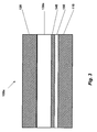
- FIG. 2 shows MEA 100 comprising anode substrate 110, cathode substrate 120 and PEM 130 disposed therebetween.
- Electrochemically separating sublayer 140 is disposed between a poison-scrubbing catalyst layer 150 and an anode electrocatalyst layer 160 which are collectively disposed between the anode substrate 110 and PEM 130 such that anode electrocatalyst layer 160 is more proximate PEM 130 than poison-scrubbing catalyst layer 150.
- MEA 110 further comprises a cathode electrocatalyst layer 170 disposed between cathode substrate 120 and PEM 130.
- Anode and cathode substrates 110, 120 are electrically conductive and porous materials.
- Exemplary suitable anode and cathode substrates 110, 120 include carbon fiber papers, such as the TGP-H or TGP-60 material supplied by Toray Industries, Inc. (Japan) and the AvCarb® material supplied by Ballard Material Products, Inc. (Lowell, MA), as well as perforated flexible expanded graphite sheets.
- a hydrophobic sublayer material such as polytetrafluoroethylene (PTFE) (not shown), may be dispersed in or on the anode or cathode substrate 110, 120.
- PTFE polytetrafluoroethylene
- Poison-scrubbing catalyst layer 150 catalyses a reaction between water and/or oxygen and the fuel poison, such as carbon monoxide, to effectively remove such poisons from the fuel stream before the fuel interacts with the anode electrocatalyst in the anode electrocatalyst layer 160.
- Poison-scrubbing catalyst layer 150 may include catalyst means for scrubbing or entrapping elements and/or compounds that are poisonous (i.e., reduce performance or efficiency) to the fuel cell, for example catalyst materials including agglomerates, mixtures or alloys of platinum-ruthenium (PtRu), platinum-tin (PtSn), platinum-molybdenum (PtMo), platinum-nickel (PtNi), platinum-gold (PtAu), platinum-iron (PtFe), platinum-cobalt (PtCo), platinum-palladium (PtPd), platinum-tungsten (PtW) or gold nanoparticles.
- PtRu platinum-ruthenium
- PtSn platinum-tin
- PtMo platinum-molybdenum
- PtNi platinum-nickel
- PtAu platinum-gold
- PtFe platinum-gold
- PtCo platinum-iron
- PtPd platinum-palladium
- PtW platinum-tungsten
- Poison-scrubbing catalyst materials in the poison-scrubbing catalyst layer 150 may be supported on catalyst support means, for example an electrically conductive carbon support, electrically conductive non-carbon support, electrically semiconductive non-carbon support or may be unsupported.
- electrically conductive carbon supports include Vulcan carbon supplied by Cabot Corp., Boston MA, acetylene black (supplied by Denki Kagaku Kogyo Kabushiki Kaisha, Japan) or others such as graphite or graphitized carbon.
- Exemplary suitable electrically conductive non-carbon supports include metal oxides such as tungsten-oxides (including WO 3 ) or metal carbides such as tungsten carbides (including W 2 C and WC).
- the catalyst support material in the poison-scrubbing catalyst layer 150 (if a catalyst support is employed) may be different from that in the anode electrocatalyst layer.
- Loading of the poison scrubbing catalyst may be 0.06 mg/cm 2 or less depending on the quality of the fuel.
- Poison-scrubbing catalyst layer 150 may further include carbon and may further include PTFE, to increase hydrophobicity.
- Electrochemically separating sublayer 140 may comprise an electrically conductive material such as carbon, graphite or graphitized carbon and may also include PTFE to increase hydrophobicity. Electrochemically separating sublayer 140 should be sufficiently porous or microporous so as to permit the flow of reactants to the anode electrocatalyst layer, permit the flow of product water out of the fuel cell, and should be sufficiently electrically conductive such that resistive losses are reduced to an acceptable level.
- electrochemically separating sublayer 140 electrochemically separates poison-scrubbing catalyst layer 150 from the anode electrocatalyst layer 160, preventing crossover of Ru and Ru species from crossing over the PEM to the cathode. This may be achieved by ensuring no ionomer material from the PEM or acidic solution is located throughout the electrochemically separating sublayer 140.
- Anode and cathode electrocatalyst layers 160, 170 may respectively include any fuel cell reaction catalyst including precious metals, such as platinum, ruthenium, tin, tungsten and molybdenum or mixtures or alloys thereof.
- the anode and cathode electrocatalysts 160, 170 may include a non-noble metal catalyst such as a chalcogenide.
- Anode and cathode electrocatalysts 160, 170 may be supported on an electrically conductive support.
- Exemplary suitable electrically conductive carbon supports include Vulcan carbon supplied by Cabot Corp., Boston MA, acetylene black (supplied by Denki Kagaku Kogyo Kabushiki Kaisha, Japan) or others such as graphite or graphitized carbon.
- Exemplary suitable electrically conductive non-carbon support includes metal oxides such as tungsten-oxides (including WO 3 ) or metal carbides such as tungsten carbides (including W 2 C and WC) and transition metal phosphides such as those disclosed in US patent application 60/829946 entitled "Catalyst Support for Fuel Cell".
- Anode and cathode electrocatalysts 160, 170 may have like or differing compositions.
- One skilled in the art will readily select a suitable anode and cathode electrocatalysts 160, 170 for a given set of fuel cell operating conditions.
- PEM 130 may take the form of membrane means for selectively conducting cations, for example perfluorinated, partially-fluorinated, or non-fluorinated ion exchange membranes.
- Exemplary suitable PEM 130 include Nafion® (supplied by DuPontTM), Gore-Select® (supplied by GoreTM), BAM® (supplied by Ballard Power Systems, Inc., Canada), and Aciplex® (supplied by Asahi Kasei Corp., Japan).
- Nafion® supplied by DuPontTM
- Gore-Select® supplied by GoreTM
- BAM® supplied by Ballard Power Systems, Inc., Canada
- Aciplex® supplied by Asahi Kasei Corp., Japan.
- One skilled in the art will readily select a suitable PEM material for a given set of fuel cell operating conditions.
- Sealing frames may be employed to seal the MEA to the fluid flow plates, provide structural support to the MEA.
- Sealing frames may be polyesters, polyethylenes, polypropylenes, polyimides, and thermosets.
- the sealing frame may be a rigid laminate material that imparts a desired rigidity to the resulting sealed MEA after sealing.
- Sealing frames may also contain a pressure-activated adhesive, such as a silicone or acrylic-based adhesive, or may contain a thermally-activated adhesive that may be a thermoset, a thermoplastic, or combinations thereof.
- a suitable frame material and adhesive material for a given set of fuel cell operating conditions. Sealing frames may further have wing areas including ports for the transport of reactants and reaction products (not shown).
- fuel flows from a fuel source having gas-phase hydrogen 40 and enters anode flow field plate 20.
- Fuel first interacts with the catalyst material in the poison-scrubbing catalyst layer 150 to remove poisoning impurities such as carbon monoxide.
- Fuel then proceeds through the electrochemically separating sublayer 140 to the anode electrocatalyst layer 160 where it is catalyzed to produce ions and electrons in the presence of the PEM 130 as described above. Electrons pass through an external circuit (not shown) to the cathode.
- oxidant flows from oxidant source 50 through the cathode flow field plates 30 and through the cathode substrate 120 where water is produced as described above.
- Electrochemically separating sublayer 140 prevents poison scrubbing catalyst materials from crossing-over into the cathode. Further, disposing the poison scrubbing layer between the anode substrate 110 and the electrochemically separating sublayer 140, prevents catalytic material from washing out of the fuel cell.
- FIG. 3 shows an alternate embodiment, MEA 100a comprising an anode substrate 110, cathode substrate 120, catalyst coated membrane 130a, electrochemically separating sublayer 140, and poison-scrubbing catalyst layer 150.
- Catalyst coated membrane (CCM) 130a includes an anode electrocatalyst layer (not shown) and cathode electrocatalyst layer (not shown) disposed on the two major surfaces of CCM 130.
- MEA 100a may be made by disposing CCM 130a between cathode substrate 110 and anode substrate 120, disposing poison-scrubbing catalyst layer 150 between anode substrate 110 and CCM 130a and disposing separating sublayer between poison-scrubbing catalyst layer 150 and CCM 130a.
- Carbon fiber paper from Toray (TGP-60) was teflonated with a PTFE content of 18% to yield an anode substrate layer.
- Poison-scrubbing layer was prepared as an ink by mixing (a) 500 grams of HiSPEC 5000 (including a 20% Pt and 10% Ru catalyst supported on Vulcan carbon, commercially available from Johnson Matthey), (b) 120 grams of Denka carbon, (c) 266 grams of 60% PTFE solution, (d) 68 grams of methyl cellulose, and (e) 3678 grams of deionized water.
- the poison-scrubbing layer ink was then coated onto anode substrate and was sintered at 365 °C, leaving a Pt-Ru poison-scrubbing catalyst layer.
- the anode substrate with poison-scrubbing layer was then dried at 180 °C under air.
- Electrochemically separating sublayer was prepared by mixing 92.42% deionized water, with 4.54% dry powder Denka carbon black, 1.95% PTFE solids dispersion available from E.I. Dupont, 1.01% Methocel A4M Premium 4000 CPS 2wt% methyl cellulose available from Dow Chemical and a 1.08% Surfynol DF110D defoamer available from St. Lawrence Chemical. The mixture was heated to 80 degrees Celsius for 50 minutes and vacuum degassed for 70 minutes at approximately 200 mbar to produce an ink slurry.
- the sublayer ink slurry was then K-coated on the anode substrate with poison-tolerant layer, dried at room temperature and sintered via a two-step sintering at 250 degrees Celsius and 365 degrees Celsius, each for 10 minutes, leaving a sublayer comprised of 79.5% carbon and 20.5% PTFE.
- a separate catalyst-coated membrane was prepared with an anode electrocatalyst layer and cathode electrocatalyst layer, each comprising carbon-supported platinum disposed on either side.
- the anode substrate (with poison-scrubbing catalyst layer and sublayer), CCM and cathode substrate were bonded at 160 °C and under 20 bar of pressure for 2.5 minutes.
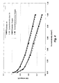
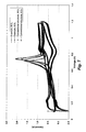
- Figure 4 shows a polarization curve performance comparison of the example structure described above and a conventional structure, comprised of a PEM disposed between a cathode electrocatalyst layer comprising platinum and an anode electrocatalyst layer comprising platinum and ruthenium each respectively disposed between gas diffusion layers.
- the polarization curve shows no negative performance impact of the example structure described above as compared to the conventional structure.
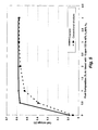
- Figure 5 shows improved carbon monoxide tolerance of the example structure as compared to the conventional structure.
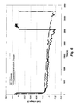
- Figure 6 shows surprisingly improved cell reversal tolerance of the example structure as compared to the conventional structure at -0.2 A/cm 2 .
- Figure 7 shows improved ruthenium crossover of the example structure as compared to the conventional structure.
Landscapes
- Chemical & Material Sciences (AREA)
- Chemical Kinetics & Catalysis (AREA)
- Electrochemistry (AREA)
- General Chemical & Material Sciences (AREA)
- Engineering & Computer Science (AREA)
- Life Sciences & Earth Sciences (AREA)
- Manufacturing & Machinery (AREA)
- Sustainable Development (AREA)
- Sustainable Energy (AREA)
- Materials Engineering (AREA)
- Composite Materials (AREA)
- Inert Electrodes (AREA)
Claims (10)
- Système (10) de pile à combustible comprenant une pile à combustible et une alimentation de réactif destinée à délivrer un réactif comprenant de l'hydrogène gazeux et des espèces empoisonnantes, vers la pile à combustible ; la pile à combustible comprenant un ensemble membrane-électrode (100), l'ensemble membrane-électrode (100) comprenant :un substrat de cathode (120) ;un substrat d'anode (110) ;une membrane d'échange de protons (130) disposée entre le substrat de cathode (120) et le substrat d'anode (110) ;une sous-couche de séparation électrochimique (140) disposée entre la membrane d'échange de protons (130) et le substrat d'anode (110) ;une couche catalytique de lavage de poison (150) disposée entre la sous-couche de séparation électrochimique (140) et le substrat d'anode (110) ;une couche électrocatalytique d'anode (160) disposée entre la membrane d'échange de protons (130) et la sous-couche de séparation électrochimique (140) ;
etune couche électrocatalytique de cathode (170) disposée entre le substrat de cathode (120) et la membrane d'échange de protons (130),caractérisé en ce que la sous-couche de séparation électrochimique (140) ne comprend pas de ionomère conducteur de cation. - Système (10) de pile à combustible selon la revendication 1, dans lequel les espèces empoisonnantes comprennent le monoxyde de carbone.
- Système (10) de pile à combustible selon la revendication 2, dans lequel la sous-couche de séparation électrochimique (140) est composée de carbone et de polytétrafluoroéthylène.
- Système (10) de pile à combustible selon la revendication 3, dans lequel la couche catalytique de lavage de poison (150) comprend un moyen catalytique destiné à laver le poison.
- Système (10) de pile à combustible selon la revendication 3, dans lequel la couche catalytique de lavage de poison (150) comprend au moins l'un parmi le platine, le ruthénium et une combinaison de ceux-ci.
- Système (10) de pile à combustible selon la revendication 3, dans lequel la couche catalytique de lavage de poison (150) est supportée sur un support catalytique.
- Système (10) de pile à combustible selon la revendication 6, dans lequel le support catalytique comprend au moins l'un parmi le carbone, l'oxyde de tungstène, le carbure de tungstène et des combinaisons de ceux-ci.
- Système (10) de pile à combustible selon la revendication 6, dans lequel le support catalytique comprend au moins l'un parmi la zéolite, la silice, l'alumine, le dioxyde de titane et des combinaisons de ceux-ci.
- Système (10) de pile à combustible selon la revendication 3, dans lequel la couche électrocatalytique d'anode (160) comprend du platine.
- Système (10) de pile à combustible selon la revendication 1, dans lequel la sous-couche de séparation électrochimique (140) est en contact physique direct avec la couche catalytique de lavage de poison (150) sur une face de la sous-couche de séparation électrochimique (140), et en contact physique direct avec la couche électrocatalytique d'anode (160) sur une face opposée de la sous-couche de séparation électrochimique (140).
Applications Claiming Priority (2)
| Application Number | Priority Date | Filing Date | Title |
|---|---|---|---|
| US11/860,354 US20090081527A1 (en) | 2007-09-24 | 2007-09-24 | Fuel cell system |
| PCT/US2008/077491 WO2009042665A1 (fr) | 2007-09-24 | 2008-09-24 | Système de pile à combustible |
Publications (2)
| Publication Number | Publication Date |
|---|---|
| EP2193565A1 EP2193565A1 (fr) | 2010-06-09 |
| EP2193565B1 true EP2193565B1 (fr) | 2015-08-26 |
Family
ID=40091361
Family Applications (1)
| Application Number | Title | Priority Date | Filing Date |
|---|---|---|---|
| EP08833982.5A Active EP2193565B1 (fr) | 2007-09-24 | 2008-09-24 | Système de pile à combustible |
Country Status (6)
| Country | Link |
|---|---|
| US (1) | US20090081527A1 (fr) |
| EP (1) | EP2193565B1 (fr) |
| KR (2) | KR101640731B1 (fr) |
| CN (1) | CN101809791B (fr) |
| CA (1) | CA2699727C (fr) |
| WO (1) | WO2009042665A1 (fr) |
Families Citing this family (9)
| Publication number | Priority date | Publication date | Assignee | Title |
|---|---|---|---|---|
| TWI408843B (zh) | 2009-12-24 | 2013-09-11 | Ind Tech Res Inst | 燃料電池流場板及其形成方法 |
| CN102130344B (zh) * | 2010-01-14 | 2013-12-18 | 财团法人工业技术研究院 | 燃料电池流场板及其形成方法 |
| CN103553585B (zh) * | 2013-10-22 | 2016-04-27 | 瑞声声学科技(深圳)有限公司 | 铁氧体陶瓷的制备方法 |
| DE202014002512U1 (de) * | 2014-03-18 | 2015-06-25 | Reinz-Dichtungs-Gmbh | Elektrochemisches System |
| WO2018038986A1 (fr) | 2016-08-25 | 2018-03-01 | Proton Energy Systems, Inc. | Assemblage membrane-électrodes et procédé de fabrication associé |
| US10454114B2 (en) | 2016-12-22 | 2019-10-22 | The Research Foundation For The State University Of New York | Method of producing stable, active and mass-producible Pt3Ni catalysts through preferential co etching |
| US11489186B2 (en) | 2017-01-26 | 2022-11-01 | Typher Yom | Air-water concentration cell |
| US10833343B2 (en) * | 2017-01-26 | 2020-11-10 | Typher Yom | Air-water concentration cell |
| CN114171750A (zh) * | 2021-11-11 | 2022-03-11 | 广东泰极动力科技有限公司 | 一种用于燃料电池膜电极的阳极催化剂及其制备方法 |
Citations (1)
| Publication number | Priority date | Publication date | Assignee | Title |
|---|---|---|---|---|
| US6517962B1 (en) * | 1999-08-23 | 2003-02-11 | Ballard Power Systems Inc. | Fuel cell anode structures for voltage reversal tolerance |
Family Cites Families (19)
| Publication number | Priority date | Publication date | Assignee | Title |
|---|---|---|---|---|
| US4911803A (en) * | 1988-07-19 | 1990-03-27 | Kunz Harold R | Composite hydrogen purification membrane and method for purifying hydrogen |
| US5395705A (en) * | 1990-08-31 | 1995-03-07 | The Dow Chemical Company | Electrochemical cell having an electrode containing a carbon fiber paper coated with catalytic metal particles |
| US5211984A (en) * | 1991-02-19 | 1993-05-18 | The Regents Of The University Of California | Membrane catalyst layer for fuel cells |
| US5242765A (en) * | 1992-06-23 | 1993-09-07 | Luz Electric Fuel Israel Limited | Gas diffusion electrodes |
| GB9507012D0 (en) * | 1995-04-05 | 1995-05-31 | Johnson Matthey Plc | Improved electrode |
| DE19544323A1 (de) * | 1995-11-28 | 1997-06-05 | Magnet Motor Gmbh | Gasdiffusionselektrode für Polymerelektrolytmembran-Brennstoffzellen |
| US5672439A (en) * | 1995-12-18 | 1997-09-30 | Ballard Power Systems, Inc. | Method and apparatus for reducing reactant crossover in an electrochemical fuel cell |
| US5922488A (en) * | 1997-08-15 | 1999-07-13 | Exxon Research And Engineering Co., | Co-tolerant fuel cell electrode |
| US6287717B1 (en) * | 1998-11-13 | 2001-09-11 | Gore Enterprise Holdings, Inc. | Fuel cell membrane electrode assemblies with improved power outputs |
| US6818341B2 (en) | 1998-12-18 | 2004-11-16 | The Regents Of The University Of California | Fuel cell anode configuration for CO tolerance |
| US6300000B1 (en) * | 1999-06-18 | 2001-10-09 | Gore Enterprise Holdings | Fuel cell membrane electrode assemblies with improved power outputs and poison resistance |
| US6936370B1 (en) * | 1999-08-23 | 2005-08-30 | Ballard Power Systems Inc. | Solid polymer fuel cell with improved voltage reversal tolerance |
| US6309769B1 (en) * | 2000-06-30 | 2001-10-30 | Plug Power Inc. | Carbon monoxide filter layer |
| GB0022895D0 (en) * | 2000-09-19 | 2000-11-01 | Johnson Matthey Plc | Anode structure |
| US6756150B2 (en) * | 2002-04-08 | 2004-06-29 | Plug Power Inc. | Fuel cell having a non-electrolytic layer |
| JP3621078B2 (ja) * | 2002-06-20 | 2005-02-16 | 田中貴金属工業株式会社 | 高分子固体電解質形燃料電池の燃料極 |
| US20040013935A1 (en) * | 2002-07-19 | 2004-01-22 | Siyu Ye | Anode catalyst compositions for a voltage reversal tolerant fuel cell |
| US7960072B2 (en) * | 2003-04-04 | 2011-06-14 | GM Global Technology Operations LLC | MEA with catalyst for oxidation of carbon monoxide |
| JP2006054165A (ja) * | 2004-07-15 | 2006-02-23 | Honda Motor Co Ltd | 固体高分子型燃料電池及び固体高分子型燃料電池の製造方法 |
-
2007
- 2007-09-24 US US11/860,354 patent/US20090081527A1/en not_active Abandoned
-
2008
- 2008-09-24 KR KR1020107008789A patent/KR101640731B1/ko active IP Right Grant
- 2008-09-24 CN CN2008801084539A patent/CN101809791B/zh active Active
- 2008-09-24 KR KR1020167011305A patent/KR20160052802A/ko not_active Application Discontinuation
- 2008-09-24 CA CA2699727A patent/CA2699727C/fr active Active
- 2008-09-24 EP EP08833982.5A patent/EP2193565B1/fr active Active
- 2008-09-24 WO PCT/US2008/077491 patent/WO2009042665A1/fr active Application Filing
Patent Citations (1)
| Publication number | Priority date | Publication date | Assignee | Title |
|---|---|---|---|---|
| US6517962B1 (en) * | 1999-08-23 | 2003-02-11 | Ballard Power Systems Inc. | Fuel cell anode structures for voltage reversal tolerance |
Also Published As
| Publication number | Publication date |
|---|---|
| CN101809791A (zh) | 2010-08-18 |
| EP2193565A1 (fr) | 2010-06-09 |
| CA2699727C (fr) | 2016-02-09 |
| CA2699727A1 (fr) | 2009-04-02 |
| CN101809791B (zh) | 2012-10-31 |
| KR20160052802A (ko) | 2016-05-12 |
| US20090081527A1 (en) | 2009-03-26 |
| KR20100058654A (ko) | 2010-06-03 |
| KR101640731B1 (ko) | 2016-07-19 |
| WO2009042665A1 (fr) | 2009-04-02 |
Similar Documents
| Publication | Publication Date | Title |
|---|---|---|
| EP2193565B1 (fr) | Système de pile à combustible | |
| US5795669A (en) | Electrode | |
| US20170098833A1 (en) | Carbon supported catalyst | |
| US8173324B2 (en) | Catalyst | |
| EP3167502B1 (fr) | Conception de cathode pour cellules électrochimiques | |
| US7226689B2 (en) | Method of making a membrane electrode assembly for electrochemical fuel cells | |
| US20020068213A1 (en) | Multiple layer electrode for improved performance | |
| EP3520161B1 (fr) | Design d'électrode de cathode pour les piles à combustible électrochimiques | |
| KR20050083660A (ko) | 연료 전지 전극 | |
| JP2000012043A (ja) | 固体高分子電解質型燃料電池用電極触媒、並びに該触媒を用いた電極、電解質膜―電極接合体および固体高分子電解質型燃料電池 | |
| EP1749322B1 (fr) | Structure d'anode pour pile a combustible | |
| CA2528141C (fr) | Unite membrane-electrodes pour piles a combustible methanol et procede de production correspondant | |
| US20140342262A1 (en) | Fuel Cell | |
| KR20210114052A (ko) | 연료 전지용 척매 | |
| AU2022315863A1 (en) | Oxygen evolution reaction catalyst | |
| US20120189933A1 (en) | Anode catalyst layers for direct oxidation fuel cells |
Legal Events
| Date | Code | Title | Description |
|---|---|---|---|
| PUAI | Public reference made under article 153(3) epc to a published international application that has entered the european phase |
Free format text: ORIGINAL CODE: 0009012 |
|
| 17P | Request for examination filed |
Effective date: 20100319 |
|
| AK | Designated contracting states |
Kind code of ref document: A1 Designated state(s): AT BE BG CH CY CZ DE DK EE ES FI FR GB GR HR HU IE IS IT LI LT LU LV MC MT NL NO PL PT RO SE SI SK TR |
|
| AX | Request for extension of the european patent |
Extension state: AL BA MK RS |
|
| RIN1 | Information on inventor provided before grant (corrected) |
Inventor name: BAI, KYOUNG, J. Inventor name: YE, SIYU Inventor name: HE, PING |
|
| DAX | Request for extension of the european patent (deleted) | ||
| 17Q | First examination report despatched |
Effective date: 20110120 |
|
| RIN1 | Information on inventor provided before grant (corrected) |
Inventor name: BAI, KYOUNG, J. Inventor name: YE, SIYU Inventor name: HE, PING |
|
| GRAP | Despatch of communication of intention to grant a patent |
Free format text: ORIGINAL CODE: EPIDOSNIGR1 |
|
| RIC1 | Information provided on ipc code assigned before grant |
Ipc: H01M 4/86 20060101AFI20150227BHEP Ipc: H01M 4/92 20060101ALI20150227BHEP Ipc: H01M 8/02 20060101ALI20150227BHEP |
|
| INTG | Intention to grant announced |
Effective date: 20150327 |
|
| GRAS | Grant fee paid |
Free format text: ORIGINAL CODE: EPIDOSNIGR3 |
|
| GRAA | (expected) grant |
Free format text: ORIGINAL CODE: 0009210 |
|
| AK | Designated contracting states |
Kind code of ref document: B1 Designated state(s): AT BE BG CH CY CZ DE DK EE ES FI FR GB GR HR HU IE IS IT LI LT LU LV MC MT NL NO PL PT RO SE SI SK TR |
|
| REG | Reference to a national code |
Ref country code: GB Ref legal event code: FG4D |
|
| REG | Reference to a national code |
Ref country code: CH Ref legal event code: EP |
|
| REG | Reference to a national code |
Ref country code: AT Ref legal event code: REF Ref document number: 745652 Country of ref document: AT Kind code of ref document: T Effective date: 20150915 |
|
| REG | Reference to a national code |
Ref country code: IE Ref legal event code: FG4D |
|
| REG | Reference to a national code |
Ref country code: DE Ref legal event code: R096 Ref document number: 602008039835 Country of ref document: DE |
|
| REG | Reference to a national code |
Ref country code: AT Ref legal event code: MK05 Ref document number: 745652 Country of ref document: AT Kind code of ref document: T Effective date: 20150826 |
|
| REG | Reference to a national code |
Ref country code: LT Ref legal event code: MG4D |
|
| PG25 | Lapsed in a contracting state [announced via postgrant information from national office to epo] |
Ref country code: NO Free format text: LAPSE BECAUSE OF FAILURE TO SUBMIT A TRANSLATION OF THE DESCRIPTION OR TO PAY THE FEE WITHIN THE PRESCRIBED TIME-LIMIT Effective date: 20151126 Ref country code: FI Free format text: LAPSE BECAUSE OF FAILURE TO SUBMIT A TRANSLATION OF THE DESCRIPTION OR TO PAY THE FEE WITHIN THE PRESCRIBED TIME-LIMIT Effective date: 20150826 Ref country code: LT Free format text: LAPSE BECAUSE OF FAILURE TO SUBMIT A TRANSLATION OF THE DESCRIPTION OR TO PAY THE FEE WITHIN THE PRESCRIBED TIME-LIMIT Effective date: 20150826 Ref country code: LV Free format text: LAPSE BECAUSE OF FAILURE TO SUBMIT A TRANSLATION OF THE DESCRIPTION OR TO PAY THE FEE WITHIN THE PRESCRIBED TIME-LIMIT Effective date: 20150826 |
|
| REG | Reference to a national code |
Ref country code: NL Ref legal event code: MP Effective date: 20150826 |
|
| PG25 | Lapsed in a contracting state [announced via postgrant information from national office to epo] |
Ref country code: PT Free format text: LAPSE BECAUSE OF FAILURE TO SUBMIT A TRANSLATION OF THE DESCRIPTION OR TO PAY THE FEE WITHIN THE PRESCRIBED TIME-LIMIT Effective date: 20151228 Ref country code: ES Free format text: LAPSE BECAUSE OF FAILURE TO SUBMIT A TRANSLATION OF THE DESCRIPTION OR TO PAY THE FEE WITHIN THE PRESCRIBED TIME-LIMIT Effective date: 20150826 Ref country code: SE Free format text: LAPSE BECAUSE OF FAILURE TO SUBMIT A TRANSLATION OF THE DESCRIPTION OR TO PAY THE FEE WITHIN THE PRESCRIBED TIME-LIMIT Effective date: 20150826 Ref country code: PL Free format text: LAPSE BECAUSE OF FAILURE TO SUBMIT A TRANSLATION OF THE DESCRIPTION OR TO PAY THE FEE WITHIN THE PRESCRIBED TIME-LIMIT Effective date: 20150826 Ref country code: IS Free format text: LAPSE BECAUSE OF FAILURE TO SUBMIT A TRANSLATION OF THE DESCRIPTION OR TO PAY THE FEE WITHIN THE PRESCRIBED TIME-LIMIT Effective date: 20151226 Ref country code: AT Free format text: LAPSE BECAUSE OF FAILURE TO SUBMIT A TRANSLATION OF THE DESCRIPTION OR TO PAY THE FEE WITHIN THE PRESCRIBED TIME-LIMIT Effective date: 20150826 Ref country code: HR Free format text: LAPSE BECAUSE OF FAILURE TO SUBMIT A TRANSLATION OF THE DESCRIPTION OR TO PAY THE FEE WITHIN THE PRESCRIBED TIME-LIMIT Effective date: 20150826 |
|
| PG25 | Lapsed in a contracting state [announced via postgrant information from national office to epo] |
Ref country code: NL Free format text: LAPSE BECAUSE OF FAILURE TO SUBMIT A TRANSLATION OF THE DESCRIPTION OR TO PAY THE FEE WITHIN THE PRESCRIBED TIME-LIMIT Effective date: 20150826 |
|
| PG25 | Lapsed in a contracting state [announced via postgrant information from national office to epo] |
Ref country code: IT Free format text: LAPSE BECAUSE OF FAILURE TO SUBMIT A TRANSLATION OF THE DESCRIPTION OR TO PAY THE FEE WITHIN THE PRESCRIBED TIME-LIMIT Effective date: 20150826 Ref country code: EE Free format text: LAPSE BECAUSE OF FAILURE TO SUBMIT A TRANSLATION OF THE DESCRIPTION OR TO PAY THE FEE WITHIN THE PRESCRIBED TIME-LIMIT Effective date: 20150826 Ref country code: CZ Free format text: LAPSE BECAUSE OF FAILURE TO SUBMIT A TRANSLATION OF THE DESCRIPTION OR TO PAY THE FEE WITHIN THE PRESCRIBED TIME-LIMIT Effective date: 20150826 Ref country code: DK Free format text: LAPSE BECAUSE OF FAILURE TO SUBMIT A TRANSLATION OF THE DESCRIPTION OR TO PAY THE FEE WITHIN THE PRESCRIBED TIME-LIMIT Effective date: 20150826 Ref country code: SK Free format text: LAPSE BECAUSE OF FAILURE TO SUBMIT A TRANSLATION OF THE DESCRIPTION OR TO PAY THE FEE WITHIN THE PRESCRIBED TIME-LIMIT Effective date: 20150826 |
|
| REG | Reference to a national code |
Ref country code: CH Ref legal event code: PL |
|
| REG | Reference to a national code |
Ref country code: DE Ref legal event code: R097 Ref document number: 602008039835 Country of ref document: DE |
|
| PG25 | Lapsed in a contracting state [announced via postgrant information from national office to epo] |
Ref country code: MC Free format text: LAPSE BECAUSE OF FAILURE TO SUBMIT A TRANSLATION OF THE DESCRIPTION OR TO PAY THE FEE WITHIN THE PRESCRIBED TIME-LIMIT Effective date: 20150826 Ref country code: RO Free format text: LAPSE BECAUSE OF FAILURE TO SUBMIT A TRANSLATION OF THE DESCRIPTION OR TO PAY THE FEE WITHIN THE PRESCRIBED TIME-LIMIT Effective date: 20150826 |
|
| REG | Reference to a national code |
Ref country code: IE Ref legal event code: MM4A |
|
| PLBE | No opposition filed within time limit |
Free format text: ORIGINAL CODE: 0009261 |
|
| REG | Reference to a national code |
Ref country code: FR Ref legal event code: ST Effective date: 20160531 |
|
| STAA | Information on the status of an ep patent application or granted ep patent |
Free format text: STATUS: NO OPPOSITION FILED WITHIN TIME LIMIT |
|
| PG25 | Lapsed in a contracting state [announced via postgrant information from national office to epo] |
Ref country code: IE Free format text: LAPSE BECAUSE OF NON-PAYMENT OF DUE FEES Effective date: 20150924 Ref country code: CH Free format text: LAPSE BECAUSE OF NON-PAYMENT OF DUE FEES Effective date: 20150930 Ref country code: LI Free format text: LAPSE BECAUSE OF NON-PAYMENT OF DUE FEES Effective date: 20150930 |
|
| 26N | No opposition filed |
Effective date: 20160530 |
|
| PG25 | Lapsed in a contracting state [announced via postgrant information from national office to epo] |
Ref country code: SI Free format text: LAPSE BECAUSE OF FAILURE TO SUBMIT A TRANSLATION OF THE DESCRIPTION OR TO PAY THE FEE WITHIN THE PRESCRIBED TIME-LIMIT Effective date: 20150826 Ref country code: FR Free format text: LAPSE BECAUSE OF NON-PAYMENT OF DUE FEES Effective date: 20151026 |
|
| PG25 | Lapsed in a contracting state [announced via postgrant information from national office to epo] |
Ref country code: BE Free format text: LAPSE BECAUSE OF FAILURE TO SUBMIT A TRANSLATION OF THE DESCRIPTION OR TO PAY THE FEE WITHIN THE PRESCRIBED TIME-LIMIT Effective date: 20150826 |
|
| PG25 | Lapsed in a contracting state [announced via postgrant information from national office to epo] |
Ref country code: MT Free format text: LAPSE BECAUSE OF FAILURE TO SUBMIT A TRANSLATION OF THE DESCRIPTION OR TO PAY THE FEE WITHIN THE PRESCRIBED TIME-LIMIT Effective date: 20150826 |
|
| PG25 | Lapsed in a contracting state [announced via postgrant information from national office to epo] |
Ref country code: HU Free format text: LAPSE BECAUSE OF FAILURE TO SUBMIT A TRANSLATION OF THE DESCRIPTION OR TO PAY THE FEE WITHIN THE PRESCRIBED TIME-LIMIT; INVALID AB INITIO Effective date: 20080924 Ref country code: BG Free format text: LAPSE BECAUSE OF FAILURE TO SUBMIT A TRANSLATION OF THE DESCRIPTION OR TO PAY THE FEE WITHIN THE PRESCRIBED TIME-LIMIT Effective date: 20150826 |
|
| PG25 | Lapsed in a contracting state [announced via postgrant information from national office to epo] |
Ref country code: GR Free format text: LAPSE BECAUSE OF FAILURE TO SUBMIT A TRANSLATION OF THE DESCRIPTION OR TO PAY THE FEE WITHIN THE PRESCRIBED TIME-LIMIT Effective date: 20150826 Ref country code: CY Free format text: LAPSE BECAUSE OF FAILURE TO SUBMIT A TRANSLATION OF THE DESCRIPTION OR TO PAY THE FEE WITHIN THE PRESCRIBED TIME-LIMIT Effective date: 20150826 |
|
| PG25 | Lapsed in a contracting state [announced via postgrant information from national office to epo] |
Ref country code: TR Free format text: LAPSE BECAUSE OF FAILURE TO SUBMIT A TRANSLATION OF THE DESCRIPTION OR TO PAY THE FEE WITHIN THE PRESCRIBED TIME-LIMIT Effective date: 20150826 |
|
| PG25 | Lapsed in a contracting state [announced via postgrant information from national office to epo] |
Ref country code: LU Free format text: LAPSE BECAUSE OF NON-PAYMENT OF DUE FEES Effective date: 20150924 |
|
| P01 | Opt-out of the competence of the unified patent court (upc) registered |
Effective date: 20230525 |
|
| PGFP | Annual fee paid to national office [announced via postgrant information from national office to epo] |
Ref country code: GB Payment date: 20230927 Year of fee payment: 16 |
|
| PGFP | Annual fee paid to national office [announced via postgrant information from national office to epo] |
Ref country code: DE Payment date: 20230927 Year of fee payment: 16 |