EP0089006B1 - Zuschneidemaschine - Google Patents
Zuschneidemaschine Download PDFInfo
- Publication number
- EP0089006B1 EP0089006B1 EP83102329A EP83102329A EP0089006B1 EP 0089006 B1 EP0089006 B1 EP 0089006B1 EP 83102329 A EP83102329 A EP 83102329A EP 83102329 A EP83102329 A EP 83102329A EP 0089006 B1 EP0089006 B1 EP 0089006B1
- Authority
- EP
- European Patent Office
- Prior art keywords
- cutting
- guide handle
- signal
- cutting tool
- drive
- Prior art date
- Legal status (The legal status is an assumption and is not a legal conclusion. Google has not performed a legal analysis and makes no representation as to the accuracy of the status listed.)
- Expired
Links
- 238000005520 cutting process Methods 0.000 title claims description 126
- 239000000463 material Substances 0.000 claims description 10
- 239000004744 fabric Substances 0.000 claims description 8
- 238000006073 displacement reaction Methods 0.000 claims description 7
- 230000001419 dependent effect Effects 0.000 claims description 4
- 230000008878 coupling Effects 0.000 claims description 3
- 238000010168 coupling process Methods 0.000 claims description 3
- 238000005859 coupling reaction Methods 0.000 claims description 3
- 230000007935 neutral effect Effects 0.000 description 11
- 238000004804 winding Methods 0.000 description 10
- 239000004020 conductor Substances 0.000 description 7
- 238000010276 construction Methods 0.000 description 3
- 238000010586 diagram Methods 0.000 description 3
- 230000006835 compression Effects 0.000 description 2
- 238000007906 compression Methods 0.000 description 2
- 241001267494 Microdes Species 0.000 description 1
- 239000012141 concentrate Substances 0.000 description 1
- 230000005284 excitation Effects 0.000 description 1
- 239000002184 metal Substances 0.000 description 1
- 230000035945 sensitivity Effects 0.000 description 1
- 230000035939 shock Effects 0.000 description 1
- 210000003813 thumb Anatomy 0.000 description 1
Images


Classifications
-
- B—PERFORMING OPERATIONS; TRANSPORTING
- B26—HAND CUTTING TOOLS; CUTTING; SEVERING
- B26D—CUTTING; DETAILS COMMON TO MACHINES FOR PERFORATING, PUNCHING, CUTTING-OUT, STAMPING-OUT OR SEVERING
- B26D5/00—Arrangements for operating and controlling machines or devices for cutting, cutting-out, stamping-out, punching, perforating, or severing by means other than cutting
- B26D5/005—Computer numerical control means
-
- B—PERFORMING OPERATIONS; TRANSPORTING
- B26—HAND CUTTING TOOLS; CUTTING; SEVERING
- B26D—CUTTING; DETAILS COMMON TO MACHINES FOR PERFORATING, PUNCHING, CUTTING-OUT, STAMPING-OUT OR SEVERING
- B26D5/00—Arrangements for operating and controlling machines or devices for cutting, cutting-out, stamping-out, punching, perforating, or severing by means other than cutting
-
- B—PERFORMING OPERATIONS; TRANSPORTING
- B26—HAND CUTTING TOOLS; CUTTING; SEVERING
- B26F—PERFORATING; PUNCHING; CUTTING-OUT; STAMPING-OUT; SEVERING BY MEANS OTHER THAN CUTTING
- B26F1/00—Perforating; Punching; Cutting-out; Stamping-out; Apparatus therefor
- B26F1/38—Cutting-out; Stamping-out
- B26F1/3806—Cutting-out; Stamping-out wherein relative movements of tool head and work during cutting have a component tangential to the work surface
- B26F1/3813—Cutting-out; Stamping-out wherein relative movements of tool head and work during cutting have a component tangential to the work surface wherein the tool head is moved in a plane parallel to the work in a coordinate system fixed with respect to the work
Definitions
- the invention relates to a cutting machine for flat material, in particular fabric cutting machine, with a support table for the flat material, with a support device which can be moved along the support table for a cutting tool which can be rotated about an axis of rotation running perpendicular to the support surface of the table, in particular a butt knife machine, with an associated cutting tool drive, and with a longitudinal drive for moving the support device along the support table and at least one further controllable drive device assigned to the support device for bringing about a controlled movement of the cutting tool relative to the support surface of the support table in a cutting direction predetermined by the orientation of a cutting edge of the cutting tool.
- the invention is concerned with a cutting machine with a bridge that can be moved by the longitudinal drive and spans the support table in the transverse direction, and with a cross slide that is mounted on the bridge and that can be moved relative to it by means of a transverse drive and that carries the cutting tool, the bridge normally being at both ends of the cutting table is supported, but may also only be supported on one side in order to reach over the cutting table in the form of a support arm.
- a cutting temping machine of this type is known, for example, from CH-A 406103 and works as an automatic cutting machine in which the data for the pattern to be cut out are either stored beforehand or obtained during operation by scanning a pattern template, which may be located directly under the fabric, and is scanned by suitable scanning elements, which detect the pattern line to be traversed at a point located at a short distance from the tool cutting edge.
- manually operated cutting machines in which the cutting tool is suspended from a carrying device, which in turn can be moved in the longitudinal direction of the cutting table by means of a part or a bridge.
- a cutting machine is described in DE-UG 81 08 075.1, in which the cutting tool is suspended on a support arm which is slidably supported in a rotatable holder, the holder itself being fastened to a spider-like carriage with three supports, which is longitudinal the cutting table can be moved by hand.
- DE-A 27 03 066 describes a cutting machine, in particular a fabric cutting machine, with a carriage which can be moved in the longitudinal direction of the support table and to which a boom is articulated, which has at least two arms which are connected to one another via a joint with a vertical joint axis, wherein at the free end of the outer arm the cutting device is fastened in such a way that it can be rotated about a vertical axis.
- a disadvantage of the known cutting machines in which the cutting device, in particular a butt knife, is moved manually through the material to be cut, that the operating personnel have to exert considerable forces, at least parts of the carrying device also having to be moved by the operator himself -
- a longitudinal motor drive is also provided, so that the carrying device can be traced in sections by a motor.
- the invention is based on the object of improving a cutting machine of the type specified at the outset in such a way that the work of the operating personnel is facilitated and increased cutting accuracy is achieved.
- a rotary encoder is assigned to the cutting tool, with the aid of which corresponding directional control signals can be generated with the angular position of the cutting tool with respect to its axis of rotation
- a guide handle is provided on the cutting tool with which the cutting tool can be manually moved into the desired position Angular position is rotatable with respect to its axis of rotation
- signal guide devices are assigned to the guide handle, by means of which at least one control signal serving as a start signal for the drive devices can be generated when acting in the handle area and that a controller is provided by which, depending on the directional control signals, the rotary encoder and the At least one control signal of the signal generating devices assigned to the guide handle can be used to generate drive control signals for the drive devices for driving the cutting tool in the cutting direction.
- the decisive advantage of the cutting machine according to the invention is that the operator only bring the cutting tool into the correct angular position and by acting in the grip area, for example by actuating a switch on the guide handle or by touching a sensor that can be reached by gripping the handle with the thumb on Housing of the Cutting tool, must signal that cutting should now take place in the direction of the tool cutting edge, ie in the cutting direction, whereupon the cutting tool is then moved in the desired direction by suitable motor drive devices without the operator having to apply the force required for this.
- the operator can thus concentrate fully on following the pattern lines specified in a suitable manner very precisely.
- a particularly simple way of driving the cutting tool by motor in the desired direction is obtained if the cutting tool is attached, in particular by means of a support arm, to a slide which can be moved along a bridge spanning the cutting table, since in this case those generated by a rotary encoder Signals about the angular position of the cutting tool with respect to its vertical axis of rotation can be converted relatively easily into corresponding x / y coordinate signals for controlling the drive motors.
- the motor drive of the cutting tool can also be easily realized with differently designed carrying devices for the cutting tool if, for example, in the boom cutting machine according to DE-A-27 03 066, corresponding resolvers for the joints of the boom and corresponding drive motors for pivoting the Arms of the boom against each other and opposite the carriage movable in the longitudinal direction of the cutting table.
- Appropriate solutions are known, for example, for the gripping arms of industrial robots, so that this need not be discussed in more detail in the context of the present application.
- this possibility can be realized, for example, in that a radially protruding from the cutting tool housing or a more or less vertically oriented guide handle designed in the manner of a control stick, when cutting in the cutting direction is desired, forwards or inwards is pressed against the cutting tool while, when a return movement is desired, it is moved backwards or is pulled outward from the tool.
- the adjusting movements or displacements of the guide handle or a movable handle part of the same relative to its zero position can be converted into corresponding control signals in various ways, for example by means of limit switches.
- the movements of a handle part of the guide handle are converted into adjusting movements of a rotary or sliding potentiometer or into a rotary movement of a resolver, in order to ultimately obtain control signals which not only indicate whether a cutting movement or a Return movement is desired, but also convey the information about the desired speed at which the cutting tool is to be moved.
- this is achieved in that the output signal of the resolver, which corresponds in amplitude and phase position to the supply voltage of the resolver to the deflection movement of the handle part, is used as an input signal for the x / v rotary encoder, from whose output signals by comparison with a reference voltage having a predetermined phase position, setpoint signals for the drive movements in the x direction and in the y direction can be obtained.
- the guide handle can, regardless of whether it is designed as a radial handle or as a kind of control stick, each have a zero position designed as a latching position and can also be freely pivoted or movable on both sides.
- spring means are provided which resiliently bias the guide handle or a movable handle part thereof into the zero position and generate a restoring force corresponding to the size of the displacement in the direction of the zero position, so that the operator must exert a force.
- the link between the extent of the displacement or the force applied on the one hand and the driving speed on the other hand for the movements in the cutting direction preferably the same as for the return movements, although in principle there is also the possibility that Rewind movements are generally faster than the movements in the cutting direction.
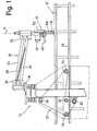
- the flat material from which the blanks are to be made is preferably fabric or webs of fabric, which are laid out in a plurality of layers one above the other on the support table 10, in particular by means of a fabric laying machine, so that several identical blanks are obtained simultaneously in one cutting operation will.
- the flat material is cut to size by means of a cutting tool, in particular by means of a butt knife machine 12, which is mounted on a carrying device and which can be rotated or pivoted about an axis of rotation A coinciding with the tool cutting edge.
- the axis of rotation A runs perpendicular to the generally at least substantially horizontally oriented support surface of the support table.
- the carrying device has a bridge 14 which extends the support table 10 in the transverse direction, i.e. extends over its full width, and which is movable in the longitudinal direction of the support table 10.
- the longitudinal direction is also referred to as the x direction
- the transverse direction is also referred to as the y direction.
- the carrying device also has a cross slide 16 which is in the y direction, i.e. transversely to the support table 10 and thus along the bridge 14. Furthermore, the carrying device has a cantilever arm 18 which has at one end a holder 20 which is fixedly connected to the cross slide 16 and the other end of which has a holder 22 to which the butt knife machine 12 is fastened. Between the two brackets 20 and 22 there are also two parallel supports 24, 26 pivotally connected to the brackets, to which an inclined tension spring 28 is assigned, the ends of which engage the brackets 20 and 22 and which relate to the free end of the cantilever arm 18 generates a certain, upward bias, which counteracts the weight of the knife machine 12.
- the drive of the bridge 14 takes place by means of a longitudinal motor 30 mounted on the bridge, which drives two toothed wheels 34 by means of a chain 32 or also by means of a toothed belt or the like, the chain 32 additionally being guided over deflection rollers 38 , of which at least one should be designed as a tension roller.
- the toothed wheels 34 mesh with a toothed rail 38, which runs along the longitudinal side of the support table 10 facing the viewer in FIG. 1.
- a corresponding toothed rail 38 can also be provided on the opposite longitudinal side of the support table 10, with the toothed wheels 34 corresponding toothed wheels 34 'then interacting with this toothed rail, which are possibly also connected to one another again via a chain and are driven by this chain, and wherein the The chain can be driven via a transverse shaft connected to a deflection roller 36.
- the cross slide 16 is driven by means of a transverse motor 40 which is mounted on the bridge 14, via a chain 42 which is fixedly connected to the cross slide 16 and runs via chain wheels 44 fixedly mounted on the bridge.
- the butt knife machine 12 is driven by a cutting tool drive in the form of a butt knife motor 48 which is flanged directly to the housing 52 of the butt knife machine 12.
- the power supply to the shock knife motor 46 takes place in the usual way via a slip ring arrangement inside the holder 22 and via flexible feed lines, as described for example in DE-A 27 03 066.
- the cutting machine according to the invention operates as a manually operated cutting machine with servo assistance.
- the butt knife machine 12 is designed in a special way, as will be explained in more detail below with reference to FIG. 3.
- a special control is provided, which will also be discussed in more detail below.
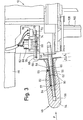
- FIG. 3 shows a detailed illustration of the butt knife machine 12, from which it becomes clear that below the butt knife motor 46 a radial of the housing 52 of the butt knife machine 12 protruding guide handle 48 is provided.
- the guide handle 48 has a rod-shaped holder 50, the inner end of which - on the right in FIG. 3 - is screwed to the housing 52 of the rotary knife machine.
- An axially displaceable grip piece 54 is seated on the holder 50 and is slidably fastened to the holder 50 by means of a countersunk screw 56.
- a shaft part of the holder 50 engages in a stepped central bore 58 of the handle 54, the inner end of the screw 55 being close to a section 58 of reduced diameter of the holder 50 which is between a shoulder 60 of the holder facing the housing 52 50 and a collar 62 provided thereon.
- the handle 54, the central bore 56 of which is longer than the shaft of the holder 50 can be shifted inwards or to the right and outwards or to the left with respect to this shaft with respect to this shaft until the inner end of the screw 55 abuts the shoulder 60 or the collar 62, it being noted that the screw 55 also passes through a sleeve 64 arranged in the bore 56 of the handle 54.
- the stroke a of the handle 54 on both sides is indicated schematically in Fig. 3.
- a bracket 66 is attached, for example welded.
- the bracket 66 is provided with an elongated hole 68, in which a driving pin 70 engages, which is fixedly connected to a toothed rack 72 which is slidably mounted on the housing 52.
- the rack 72 is provided with a groove 74 into which the switching arm 76 of a microswitch 78 can fall when the handle 54 is moved into its neutral position or central position shown in FIG. 3. If the switching arm 76 or a scanning roller provided thereon is located in the groove 74, as shown in FIG. 3, then the microswitch 78 designed as an on / off switch is opened.
- a prestressed compression spring 82 is located between the outer end of the sleeve 64 and a shoulder of the central bore 56 of the grip piece 54 between two disks 80, and the central bore 56 is located in the holder 50 at the height of this shoulder Pin 84 is provided, the ends of which protrude outward beyond the circumference of the shaft.
- a resolver 86 is also mounted on the housing 52 of the rotary knife machine 12, on the shaft of which a pinion 88 is seated, which meshes with the toothed rack 72.
- an inward displacement of the handle 54 causes the pinion 88 to rotate and consequently the shaft of the resolver 86 to rotate in the counterclockwise direction.
- the shaft of the resolver 88 is rotated clockwise. 3
- the microswitch 78 for releasing the drives can be closed by pressing the guide handle 48 or the handle 54, and secondly a signal can be generated with the help of the resolver 86, which corresponds to the force exerted on the handle 48 F is proportional.
- This signal has a predetermined size and phase position in accordance with the usual structure of resolvers, in particular linear resolvers.
- the output signal of the resolver 86 serves as an input signal for an x / v rotary encoder 87, which converts the angle of rotation of the rotary knife machine 12 relative to the holder 22 into two mutually phase-shifted signals which indicate the x component and the y component of a feed movement in the case of the respective correspond to the angular starting position of the straight knife machine 12.
- the impact knife motor 46 is a three-phase motor, which is connected to the three phase conductors of a three-phase network via a three-pole, manually operable switch 90, which can be provided on the housing 52 or optionally also on the holder 22 (not shown) , in which a main switch (not shown) is generally provided, by means of which the internal three-phase network can be completely separated from the public network.
- the three phase conductors are designated in the usual way with the identification letters R, S and T, while the center conductor drawn with a dash-dotted line is designated with the reference symbol Mp.
- an input of a generator 94 and a comparator 96 is also connected via a switch 92.
- the generator 94. generates an alternating voltage based on the mains voltage, which usually has a frequency of 50 Hz. with a significantly higher frequency of 400 Hz, for example, which is applied to one winding of the resolver 86 via two outputs of the generator 94.
- the two connections of the secondary winding of the resolver 86 are connected to the two connections of a primary winding of the x / y encoder 87.
- the two other windings of the rotary encoder 87 are each connected via a pair of conductors to a pair of inputs of a frequency discriminator 98, to which the 400 Hz voltage from the generator 94 is also fed as a reference signal on the input side.
- the generator 98 is provided with two outputs, at which setpoint signals are available which correspond to the desired movement of the rotary knife machine 12 in the x direction and in the y direction. These signals are fed to the comparator 96 on the one hand and to the controller 100 on the other.
- the controller 100 which is also supplied with two signals on the input side, which correspond to the differences between the pairs of target and actual values to be compared in the comparator 96, has two outputs via which the armature current of the two traction motors 30, 40 is supplied whose field windings are fed with fixed currents.
- This supply takes place from a power supply or rectifier part 96a, which is part of the comparator 96.
- two electromagnetic clutches 104, 106 are also fed via a switch 102, which are inserted into the drive connection between the motors 30 and 40 on the bridge 14 or with the cross slide 16.
- a tachometer generator 30a or 40a or the like is also connected to the two motors 30 and 40, via which the required actual value information is supplied to two corresponding inputs of the comparator 96.
- the operator When working with the cutting machine according to the invention, the operator first swivels the butt knife machine 12 on its guide handle 48 into the desired angular position, i.e. normally in the direction in which the cutting edge 108 of the straight knife 110 diametrically opposite the handle 48 points in the cutting direction in which a cut is to be made in the flat material.
- the ram knife machine 12 When the ram knife machine 12 is angularly aligned and when the ram knife motor 46 is turned on, the operator pushes the handle 48 or handle 54 in the cutting direction so that the handle 54 is moved toward the housing 52, thereby turning on the microswitch 78 and a rotation of the resolver 86 which is dependent on the magnitude of the acting force is effected.
- the output signal of the resolver 88 generated in this way is dependent in its amplitude on the angle of rotation and in its phase position on the direction of rotation.
- This signal serves as an input signal for the x / y rotary encoder 87, the two other coils of which are then split into two signals assigned to the x-direction and the y-direction as a function of the angular position of the ram knife machine 12, from their amplitude and phase position compared to that 400 Hz signal generated by generator 94, two setpoint signals are derived.
- the angle information to the rotary encoder 87 is transmitted due to a mechanical connection between the rotary encoder machine 12 and its motor 46, as is indicated by the dashed line between elements 46 and 87 in FIG. 4.
- the setpoint signals from the output of the discriminator 98 are compared in the comparator 96 with the actual value signals from the tachometer generators 30a and 40a in order to generate difference signals which are fed to the controller 100.
- the operator can reverse the drive direction at any time by pulling the handle 54 in order to return the butt knife machine 12 along an existing cut and to make a cut again at the desired location.
- the overrun control described ensures that the operator has to exert only slight forces on the guide handle 48, while the major part of the force required for moving the ram knife machine 12 is applied by the traction motors 30, 40.
- FIG. 5 again shows the rotary knife motor 48 and the rotary angle transmitter 87 mechanically coupled therewith, the switch 90, via which the motor 46 is connected to the three-phase network, being designed as a lockable switch, to which an undervoltage release 111 is assigned, which prevents the cutting tool from starting unexpectedly after a voltage failure when the voltage returns.
- the switch 90 via which the motor 46 is connected to the three-phase network, being designed as a lockable switch, to which an undervoltage release 111 is assigned, which prevents the cutting tool from starting unexpectedly after a voltage failure when the voltage returns.
- the connections to the three-phase network are made via a terminal strip 114, which also has seven connections for the rotary encoder 86 and microde microswitch 78 as well as for a further electrical line (for example reference potential).
- the arrangement of rotary encoder 86 and microswitch 78 is indicated as a block 116.
- Fig. 5 it is also shown in detail that the required voltage of 220 V to earth is obtained with the aid of a transformer 118, the primary side of which is between the phase conductors R and S and the secondary side of which is grounded with the connections U and V in accordance with the applicable regulations .
- Two fuses are provided on the primary side of the transformer 118, as is also the case with the further transformers to be mentioned below on the primary side.
- a corresponding fuse is also inserted in connection U.
- a first transformer 120 between the connections U and V is the primary winding of a first transformer 120, the secondary winding of which has two connections 1 ', 2', at which an AC voltage of 24 V is available, which is supplied to the comparator 96, which is shown in FIG. 6 is shown, where the connections 1 'and 2' are shown again.
- a second transformer 122 is also connected on the primary side to the connections U and V and has a tapped secondary winding with connections 3 ', 4', 5 '. Between these connections, which are connected to the generator 94, two voltages of 15 V each are available. Two further connections 6 ', 7' are connected directly to the connections U, V via associated fuses. The AC units 98, 100 and 96 are supplied with an AC voltage of 220 V via the connections 6 'and 7'.
- Another transformer 124 is connected on the primary side via fuses to the connections U and V and on the secondary side by inserting a further fuse to a rectifier bridge 126. The transformer 124 and the bridge 126 correspond to the rectifier part 96a of the comparator 96 in FIG. 4.
- the direct current output Four parallel branches are connected to the bridge 126, the first of which contains the series connection of a switch 128 for switching on the couplings 104 and 106 and a relay 130 which has normally open contacts 130.1 and 130.2 in the second and third parallel branches, respectively.
- the second parallel branch contains the normally open contact 130.1, the microswitch 78 and a relay 132, which has a normally open contact 132.1 in the third parallel branch.
- the third parallel branch contains, in series with the normally open contact 130.2 and normally open contact 132.1, a switch 134 and a further relay 136 which has two normally open contacts 136.1 and 136.2 and two normally closed contacts 136.3 and 136.4 in the armature circuits of the traction motors 30, 40 (FIG. 7).
- a lamp 138 is provided in the fourth parallel branch, which indicates that the main switch (not shown) is switched on.
- the relay 130 ensures that the motors 30, 40 can only be switched on via the microswitch 78 when the clutches are switched on.
- the relay 132 ensures that the circuit for the armature current is switched on when the motors 30, 40 are switched on and that the armature is short-circuited immediately when the motors 30, 40 are switched off in order to achieve rapid braking, the armature circuit (FIG. 7) there is a potentiometer 140, on which the desired ohmic resistance of the short-circuit path can be set.
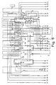
- FIG. 6 shows the generator 94, the comparator 96, the discriminator 98 and the controller 100 with their connections. These four circuits are commercially available, more or less largely integrated circuits, which are manufactured, for example, by Messer Gr understandheim, Germany, generator 94 being the type designation H 100, discriminator 98 being the type designation H 200, and the comparator 96 (without rectifier part 96a) has the type designation H 511 and the controller 100 has the type designation H 404.
- the generator 94 is connected on the input side to the connections 3 ', 4' and 5 ', a voltage of 15 V being present between these connections.
- the generator 94 supplies an alternating voltage with a frequency of 400 Hz and an amplitude of 26 V at two connections 8 ′ and 9 ′. This voltage is fed to the encoder 86 on the input side.
- the generator 94 supplies a reference signal to the discriminator 98 via two connecting lines 144, 146, which corresponds to the phase position of the signal between the connections 8 'and 9'.
- the discriminator 98 has four further connections 24 ′ to 27 ′ on the input side, which are connected to the four output lines of the x / y rotary encoder 87.
- the input connections 28 'and 29' of the rotary encoder 87 are connected directly to the two output connections of the resolver 86, which are not specified in any more detail, on the secondary side of which a potentiometer 148 is provided for adjusting the amplitude of its output signal, which ultimately specifies the maximum speed for the traction motors .
- Signals corresponding to the desired values of x and y are transmitted to the comparator via two output lines 150, 152 of the discriminator 98.
- generator 98 receives an AC voltage of 220 V from terminal 6 ' fed against earth.
- Two further connections 15 ', 16' from the minus side of the tachometer generators 30a and 40a (FIG. 7) are each connected to an input of the discriminator 98 and the controller 100.
- the discriminator 98 and the controller 100 are still connected to one another via four lines 154 to 160, via which signals obtained by half-wave rectification from the signals on the lines 24 'to 27' are applied to the controller.
- the controller 100 like the comparator 96, is connected to two connections 12 ', 13' which form one connection of the armature circuit of the traction motors 30 and 40, respectively.
- the second connection 10 'or 11' of these armature circuits is connected directly to the grounded connection 6 '.
- two connecting lines 162, 164 are also provided, via which signals are transmitted which correspond to the determined difference between the respective target and actual values.
- the comparator 96 is also connected to the terminal 7 ', so that a supply with an AC voltage of 220 V is also ensured for the comparator 96, which has its own ground connection 166.
- the comparator 96 is connected to two connections 14 'and 17', which represent the positive connection of the tacho generators 30a and 40a.
- the comparator 96 thus receives the two voltages present via the tacho generators 30a and 40a via the connections 14 'to 17'.
- the comparator 96 is also connected to the connections 1 and 2 ', via which an AC voltage of 24 V is supplied to it from the secondary side of the transformer 120 (FIG. 5).
- Four further outputs of the comparator 96 are connected to connections 18 'to 21', the excitation windings of the couplings 104 and 106 lying between the connections 18 'and 19' according to FIG. 7 and a direct voltage of between the connections 20 'and 21' 196 V is available for the field windings 30b and 40b of the motors 30 and 40, respectively.
- a connecting line 168 is also provided, each of which is connected to one connection of the discriminator 98 and the controller 100 and to two connections of the comparator 96. An AC voltage of 220 V is present on this connecting line.
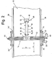
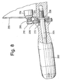
- a guide handle 202 is attached to a housing 200 of the rotary knife machine so that it can rotate about its longitudinal axis 204.
- a toothed disc 206 is fastened to this guide handle, inside which a return spring 208 designed as a coil spring is accommodated, which engages with one end on a pin 210 fastened to the housing 200 and with its other end on a pin 212 fastened on the guide handle 202 and the Attempt to hold the guide handle in a zero or neutral position. From this zero position, the guide handle can be turned against the action of the return spring 208 in both directions, for example by 45 ° in each direction, until stops not shown prevent further turning of the guide handle.
- An electrical potentiometer 214 is mounted inside the housing 200, and a pinion 216 is fastened on the axis leading out of the housing 200.
- a toothed belt 218 runs over this and the toothed pulley 206.
- the potentiometer 214 takes the place of the resolver 86 of the embodiment according to FIG. 3, while an equivalent to the microswitch 78 of the embodiment according to FIG. 3 was not drawn in the variant according to FIG. 8.
- a microswitch can easily be provided in order to sense the zero or neutral position of the guide handle 202 designed as a rotary handle.
- the rotary knife machine In the zero or neutral position of the guide handle 202, the rotary knife machine thus remains stationary, while the latter, for example, when the guide handle 202 is rotated about its longitudinal axis. moves forward faster and faster in the clockwise direction, moves backward faster and faster with a counterclockwise rotation, the travel speed being proportional to the angle of rotation of the guide handle from its zero position.
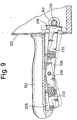
- FIG. 9 shows a guide handle 224 fixedly attached to the housing 222 of the rotary knife machine, which has a groove-shaped recess 226 at the bottom.
- a double-armed rocker button 228 is pivotally mounted about an axis 230 attached to the guide handle.
- the two arms of the rocker button are under the action of springs 232, which strive to hold the rocker button in the zero or neutral position shown with solid lines.
- an arcuate toothed rack 236 is attached, which meshes with a pinion 238 on the axis of a potentiometer 240, which is mounted inside the housing 222 and functions in accordance with the potentiometer 214 according to the embodiment Fig. 8 corresponds. Accordingly, in the zero or neutral position of the rocker button 228, the ram knife machine stands still, for example the left arm of the rocker button 228 as shown in FIG.
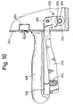
- a guide handle 246 is in turn firmly attached to a housing 224 of the butt knife machine. This too has a groove-shaped recess 245 on its underside, in which a control button 250 is accommodated. This extends through a slot in the housing 244 and is articulated within the housing by means of an axle 252.
- a gear segment 258 is molded onto the latter, which meshes with a pinion 260 on the axis of a potentiometer 262.
- an electrical changeover switch 264 is attached, with which the travel drive for the rotary knife machine can be switched from the “forward drive” state to the “reverse drive” state, while only via the potentiometer 262 in this embodiment the absolute value of the travel speed is controlled, the greater the more the control button 250 is pivoted counterclockwise from its zero position against the action of the spring 254.
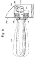
- a guide handle designated as a whole by 270, extends through a slot in a housing 272 of the rotary knife machine and is pivotably mounted by means of an axis 274, which is mounted stationary in the interior of the housing.
- the guide handle is also under the action of two springs 276 which tend to hold the guide handle in the neutral position shown in solid lines in FIG. 11.
- 11 left end of the guide handle 217 forms a gear segment 278, which meshes with a pinion 280 on the axis of a potentiometer 282.
- the function of this embodiment corresponds to that according to Fig. 8, only with the difference that a rotary movement takes the place of a rotary movement of the guide handle, i.e. in the neutral or neutral position of the guide handle 270, the ram knife machine is at a standstill, the guide handle is pressed down, i.e. Swiveled clockwise about axis 274, the ram knife machine moves forward, if the guide handle is raised, the ram knife machine moves backwards, the absolute value of the travel speed corresponding to the size of the deflection angle of the guide handle from its zero or neutral position.
Landscapes
- Engineering & Computer Science (AREA)
- Life Sciences & Earth Sciences (AREA)
- Forests & Forestry (AREA)
- Mechanical Engineering (AREA)
- General Engineering & Computer Science (AREA)
- Control Of Cutting Processes (AREA)
- Treatment Of Fiber Materials (AREA)
Applications Claiming Priority (2)
| Application Number | Priority Date | Filing Date | Title |
|---|---|---|---|
| DE3208746 | 1982-03-11 | ||
| DE3208746A DE3208746A1 (de) | 1982-03-11 | 1982-03-11 | Zuschneidemaschine |
Publications (2)
| Publication Number | Publication Date |
|---|---|
| EP0089006A1 EP0089006A1 (de) | 1983-09-21 |
| EP0089006B1 true EP0089006B1 (de) | 1986-07-23 |
Family
ID=6157899
Family Applications (1)
| Application Number | Title | Priority Date | Filing Date |
|---|---|---|---|
| EP83102329A Expired EP0089006B1 (de) | 1982-03-11 | 1983-03-10 | Zuschneidemaschine |
Country Status (6)
| Country | Link |
|---|---|
| US (1) | US4557051A (cg-RX-API-DMAC10.html) |
| EP (1) | EP0089006B1 (cg-RX-API-DMAC10.html) |
| JP (1) | JPS59500176A (cg-RX-API-DMAC10.html) |
| DE (2) | DE3208746A1 (cg-RX-API-DMAC10.html) |
| ES (1) | ES8401356A1 (cg-RX-API-DMAC10.html) |
| WO (1) | WO1983003219A1 (cg-RX-API-DMAC10.html) |
Families Citing this family (5)
| Publication number | Priority date | Publication date | Assignee | Title |
|---|---|---|---|---|
| DE3414123A1 (de) * | 1984-04-14 | 1985-10-17 | Krauss U. Reichert Gmbh + Co Kg Spezialmaschinenfabrik, 7012 Fellbach | Zuschneidemaschine fuer flachmaterial |
| JPH0523594Y2 (cg-RX-API-DMAC10.html) * | 1988-01-22 | 1993-06-16 | ||
| DE8908720U1 (de) * | 1989-07-18 | 1989-09-07 | Carl Schmale GmbH & Co KG, 4434 Ochtrup | Querschneidevorrichtung für bahnförmiges Gut, insbesondere Textilbahnen |
| US20100319507A1 (en) * | 2009-06-18 | 2010-12-23 | Tse James K | Cutting device |
| US8387495B1 (en) * | 2009-08-18 | 2013-03-05 | The United States Of America As Represented By The Secretary Of The Navy | Portable cutting tool, kit, and methods for removing damaged surfaces |
Family Cites Families (10)
| Publication number | Priority date | Publication date | Assignee | Title |
|---|---|---|---|---|
| US2742964A (en) * | 1955-05-10 | 1956-04-24 | Levin David | Cloth cutting table and machine |
| US2877550A (en) * | 1958-07-16 | 1959-03-17 | Eastman Machine Co | Paper pattern cutting machine |
| US3618687A (en) * | 1969-07-01 | 1971-11-09 | Hoover Co | Power propelled suction cleaner |
| US3780607A (en) * | 1972-01-03 | 1973-12-25 | Gerber Garment Technology Inc | Method and apparatus for cutting sheet material |
| US3803960A (en) * | 1972-12-11 | 1974-04-16 | Gerber Garment Technology Inc | System and method for cutting pattern pieces from sheet material |
| FR2237244A1 (cg-RX-API-DMAC10.html) * | 1973-07-12 | 1975-02-07 | Intercontinental Trading Cy | |
| DE2703066C2 (de) * | 1977-01-26 | 1985-10-17 | Krauss U. Reichert Gmbh + Co Kg Spezialmaschinenfabrik, 7012 Fellbach | Zuschneidemaschine für Flachmaterial |
| US4092777A (en) * | 1976-03-16 | 1978-06-06 | Krauss U. Reichert Gmbh & Co. Kg Spezialmaschinenfabrik | Cutting-out machine for flat material |
| DE7614335U1 (de) * | 1976-05-06 | 1977-10-20 | Krauss U. Reichert Spezialmaschinenfabrik, 7012 Fellbach | Handgefuehrte zuschneidemaschine fuer flachmaterial |
| US4403416A (en) * | 1981-02-06 | 1983-09-13 | N.C.A. Co., Ltd. | Cloth-cutting machine |
-
1982
- 1982-03-11 DE DE3208746A patent/DE3208746A1/de not_active Withdrawn
-
1983
- 1983-03-10 US US06/545,902 patent/US4557051A/en not_active Expired - Fee Related
- 1983-03-10 WO PCT/DE1983/000043 patent/WO1983003219A1/de not_active Ceased
- 1983-03-10 EP EP83102329A patent/EP0089006B1/de not_active Expired
- 1983-03-10 JP JP58501099A patent/JPS59500176A/ja active Granted
- 1983-03-10 DE DE8383102329T patent/DE3364611D1/de not_active Expired
- 1983-03-10 ES ES520467A patent/ES8401356A1/es not_active Expired
Also Published As
| Publication number | Publication date |
|---|---|
| EP0089006A1 (de) | 1983-09-21 |
| DE3364611D1 (en) | 1986-08-28 |
| ES520467A0 (es) | 1983-12-16 |
| JPS6224545B2 (cg-RX-API-DMAC10.html) | 1987-05-28 |
| WO1983003219A1 (fr) | 1983-09-29 |
| ES8401356A1 (es) | 1983-12-16 |
| DE3208746A1 (de) | 1983-10-20 |
| US4557051A (en) | 1985-12-10 |
| JPS59500176A (ja) | 1984-02-02 |
Similar Documents
| Publication | Publication Date | Title |
|---|---|---|
| DE2723063C2 (de) | Elektromechanische Baueinheit für ein Lichtbogen-Schweißgerät | |
| DE68920497T3 (de) | Apparat zum stufenweisen Abisolieren von Draht. | |
| DE69619909T2 (de) | Verfahren und vorrichtung zum bearbeiten eines mechanischen werkstücks | |
| DE3784417T2 (de) | Bedienungseinrichtung fuer elektrokettenzug. | |
| EP0606575A1 (de) | Hubeinrichtung | |
| DE19849976A1 (de) | Motorbetriebene Schere | |
| DE19911005A1 (de) | Verfahren zur Steuerung eines Scheibenmikrotoms | |
| DE2530056C3 (de) | Vorrichtung an einer Nibbelmaschine zum schrittweise selbsttätigen Vorschub des Werkstückträgers | |
| DE1946220A1 (de) | Aufwickelvorrichtung fuer Draehte,Litzen,Seile od.dgl. | |
| EP0087644A1 (de) | Mehrfach-Wickelwendemaschine | |
| DE1596464C3 (de) | Vorrichtung zum fernsteuerbaren Einstellen von werkzeugtragenden Schlitten | |
| DE3132127C2 (de) | Zuschneidevorrichtung für Flachmaterial wie Stoffe, Folien und dergleichen | |
| EP0089006B1 (de) | Zuschneidemaschine | |
| DE4204153A1 (de) | Winde | |
| DE2010192A1 (cg-RX-API-DMAC10.html) | ||
| DE1130031B (de) | Umschalter, insbesondere zweipoliger Umschalter fuer einen Gleichstrommotor | |
| DE2755597A1 (de) | Geschwindigkeitssteuervorrichtung fuer den wagen einer stofflegemaschine | |
| DE1936915A1 (de) | Roentgenschichtaufnahmegeraet | |
| DE19808694C2 (de) | Verfahren und Vorrichtung zur Steuerung einer Hubarbeitsbühne | |
| DE2435498A1 (de) | Analoge steuervorrichtung fuer die anschlaglose wegbegrenzung von werkzeugmaschinen | |
| DE102019102404B4 (de) | Vorrichtung zum Schneiden eines mit einem Verstärkungselement versehenen Schlauchs | |
| DE102014106106B4 (de) | Beschichtungsvorrichtung und Verfahren zum Beschichten einer Werkstückfläche | |
| DE3047976A1 (de) | Rollenschneidmaschine | |
| DE19511372A1 (de) | Kombinierte Abisolier-/Crimpvorrichtung | |
| DE1286876B (de) | Feineinstellvorrichtung fuer mindestens zwei auf einem gemeinsamen hin- und hergehend angetriebenen Schlitten montierte Werkzeuge |
Legal Events
| Date | Code | Title | Description |
|---|---|---|---|
| PUAI | Public reference made under article 153(3) epc to a published international application that has entered the european phase |
Free format text: ORIGINAL CODE: 0009012 |
|
| AK | Designated contracting states |
Designated state(s): DE FR GB IT SE |
|
| 17P | Request for examination filed |
Effective date: 19830930 |
|
| GRAA | (expected) grant |
Free format text: ORIGINAL CODE: 0009210 |
|
| AK | Designated contracting states |
Kind code of ref document: B1 Designated state(s): DE FR GB IT SE |
|
| ET | Fr: translation filed | ||
| REF | Corresponds to: |
Ref document number: 3364611 Country of ref document: DE Date of ref document: 19860828 |
|
| ITF | It: translation for a ep patent filed | ||
| PLBE | No opposition filed within time limit |
Free format text: ORIGINAL CODE: 0009261 |
|
| STAA | Information on the status of an ep patent application or granted ep patent |
Free format text: STATUS: NO OPPOSITION FILED WITHIN TIME LIMIT |
|
| 26N | No opposition filed | ||
| PG25 | Lapsed in a contracting state [announced via postgrant information from national office to epo] |
Ref country code: GB Effective date: 19890310 |
|
| PG25 | Lapsed in a contracting state [announced via postgrant information from national office to epo] |
Ref country code: SE Effective date: 19890311 |
|
| GBPC | Gb: european patent ceased through non-payment of renewal fee | ||
| PG25 | Lapsed in a contracting state [announced via postgrant information from national office to epo] |
Ref country code: FR Free format text: LAPSE BECAUSE OF NON-PAYMENT OF DUE FEES Effective date: 19891130 |
|
| PG25 | Lapsed in a contracting state [announced via postgrant information from national office to epo] |
Ref country code: DE Effective date: 19891201 |
|
| REG | Reference to a national code |
Ref country code: FR Ref legal event code: ST |
|
| EUG | Se: european patent has lapsed |
Ref document number: 83102329.6 Effective date: 19900124 |