EP0088680A2 - Workpiece assembly or processing machines - Google Patents
Workpiece assembly or processing machines Download PDFInfo
- Publication number
- EP0088680A2 EP0088680A2 EP83400419A EP83400419A EP0088680A2 EP 0088680 A2 EP0088680 A2 EP 0088680A2 EP 83400419 A EP83400419 A EP 83400419A EP 83400419 A EP83400419 A EP 83400419A EP 0088680 A2 EP0088680 A2 EP 0088680A2
- Authority
- EP
- European Patent Office
- Prior art keywords
- pallet
- module
- belt
- installation according
- transverse
- Prior art date
- Legal status (The legal status is an assumption and is not a legal conclusion. Google has not performed a legal analysis and makes no representation as to the accuracy of the status listed.)
- Granted
Links
Images


Classifications
-
- B—PERFORMING OPERATIONS; TRANSPORTING
- B23—MACHINE TOOLS; METAL-WORKING NOT OTHERWISE PROVIDED FOR
- B23Q—DETAILS, COMPONENTS, OR ACCESSORIES FOR MACHINE TOOLS, e.g. ARRANGEMENTS FOR COPYING OR CONTROLLING; MACHINE TOOLS IN GENERAL CHARACTERISED BY THE CONSTRUCTION OF PARTICULAR DETAILS OR COMPONENTS; COMBINATIONS OR ASSOCIATIONS OF METAL-WORKING MACHINES, NOT DIRECTED TO A PARTICULAR RESULT
- B23Q7/00—Arrangements for handling work specially combined with or arranged in, or specially adapted for use in connection with, machine tools, e.g. for conveying, loading, positioning, discharging, sorting
- B23Q7/14—Arrangements for handling work specially combined with or arranged in, or specially adapted for use in connection with, machine tools, e.g. for conveying, loading, positioning, discharging, sorting co-ordinated in production lines
- B23Q7/1426—Arrangements for handling work specially combined with or arranged in, or specially adapted for use in connection with, machine tools, e.g. for conveying, loading, positioning, discharging, sorting co-ordinated in production lines with work holders not rigidly fixed to the transport devices
- B23Q7/1447—Arrangements for handling work specially combined with or arranged in, or specially adapted for use in connection with, machine tools, e.g. for conveying, loading, positioning, discharging, sorting co-ordinated in production lines with work holders not rigidly fixed to the transport devices using endless conveyors
- B23Q7/1452—Arrangements for handling work specially combined with or arranged in, or specially adapted for use in connection with, machine tools, e.g. for conveying, loading, positioning, discharging, sorting co-ordinated in production lines with work holders not rigidly fixed to the transport devices using endless conveyors comprising load-supporting surfaces
-
- B—PERFORMING OPERATIONS; TRANSPORTING
- B65—CONVEYING; PACKING; STORING; HANDLING THIN OR FILAMENTARY MATERIAL
- B65G—TRANSPORT OR STORAGE DEVICES, e.g. CONVEYORS FOR LOADING OR TIPPING, SHOP CONVEYOR SYSTEMS OR PNEUMATIC TUBE CONVEYORS
- B65G35/00—Mechanical conveyors not otherwise provided for
- B65G35/06—Mechanical conveyors not otherwise provided for comprising a load-carrier moving along a path, e.g. a closed path, and adapted to be engaged by any one of a series of traction elements spaced along the path
Definitions
- the invention relates to improvements to machines for assembling and / or machining parts.
- the invention is characterized by the fact that, for driving the pallets, a multiplicity of belts is used in a module, in principle each assigned to a straight course in one direction, the driving of the multiple belts of a module being however ensured from a single electric motor, pulleys with several grooves ensuring, if necessary, the transmission of the movement of a belt to a other belt.
- the invention also provides for shaping the underside of a pallet so as to be able to cooperate with the belts along three determined levels, one of the levels of the belts corresponding to the drive in the longitudinal direction, that is to say in parallel on the front face of the machine, the other level to the drive in the perpendicular or transverse direction, and a third level being provided to facilitate the passage from a drive in one direction to a drive in the perpendicular direction by a drive transient, for example transverse.
- the invention is further characterized by the application, to ensure the support and mobility of the pallets, of rolling or handling balls, known per se, allowing progression on at least one track provided on the bottom of the module.
- the invention provides for the use of belts with circular cross-section, made of a usual material for belts.
- such a belt cooperates with a banded region with ridges on the underside of the pallet.
- the invention advantageously applies to a palette of type comprising, on the underside of the plate, pads carrying coding members and at the ends of which are provided pads.
- the three training levels are then determined by the lower faces of the plate, the pads and the studs, respectively.
- the handling balls are housed in the studs.
- striated parts for the purpose of identifying or locating pallets by forming striations on a metal strip attached to the underside of a plastic pad and by providing striated metal strips of lengths. different for one side and the opposite side of a pallet.
- the rapid return module 21 provides a channel 22 for the movement of a workpiece pallet 23.
- the pallet 23 comprises a plate or pallet body 24 (FIG. 2) with a rectangular configuration, for example square, limited by an upstream edge 25 (or right as seen by an observer placed at the front of the machine), a downstream or left edge 26, a front edge 27 and a rear edge 28.
- Two transverse pads 34 and 35 of generally parallelepiped shape, protrude downward relative to the underside 36 of the plate 24.
- each pad for example the pad 34
- the striated strips on the pads are diagonally symmetrical, that is to say that the strips of the same length are adjacent to diagonally opposite angles of the pallet. We can thus distinguish one of the edges of the pallet from the opposite edge and we take advantage of this arrangement for the automatic control of the movement of the pallets by cooperation with sensors presented by the bottom of the modules.
- Each shoe houses, in its central part, three longitudinal shoes or keys 52 1 , 52 2 , 52 3 independently mounted for rotation about the same transverse axis 53 and the lower face of which has a bevel, each shoe can take two positions , one in which its beveled end projects with respect to the underside 37 of the shoe and the other in which no part of the shoe projects with respect to said bottom face.
- each shoe has two studs 56, 57, of rectangular outline, which house rolling balls or handling balls respectively 61, 62 projecting with respect to the lower faces 63, 64 of the studs.
- Such balls well known per se and manufactured for example by SKF, have an invisible part placed in a housing, the gap between the ball and the wall of the housing. being filled with very small balls, so that the rotation of the ball around its center is practically without friction. !
- the pallet 23 rests by means of the balls 62, 62 'of its pads 34, 35, in a raceway 65 formed on the upper face 66 of a bar 67 fixed to the bottom 68 of the module 21 by screws 60
- the pallet 23 is driven by the cooperation of its knurled or striated strip 29 with a belt 69 of circular cross section resting on rollers 71 projecting from the internal face 72 of an anterior rail 73 fixed on the bottom 68 of the module 21 by screws 74. It is the weight of the pallet 23 which ensures the pressure contact between the ribbed strip 29 and the belt 69 allowing the drive.
- the opposite edge 28 of the pallet can cooperate with a recess 75 which has the upper part of a rear rail 76 fixed to the bottom 68 by screws 77.
- the front rail 73 also has a recess 78 from which the internal edge of the pallet is opposite.
- the strand 69 is part of a belt 81 disposed in a closed circuit by its engagement in the respective grooves of pulleys 82 and 83 with a vertical axis provided at the right front end 84 and at the left front end 85 of the module 21.
- the track 22 of the module 21 is extended by a track 86 of a module 87 directed generally perpendicularly to the module 21.
- the module 87 has at the rear part of its inlet a pulley 88 with a vertical axis over which passes a belt 93 arranged in a closed circuit with two parallel strands 94 and 95, the length of which is substantially equal to the width of the module 87, said closed circuit being defined by a second pulley 94 'with a vertical axis with two grooves.
- the drive of the pallet by the strand 98 of the belt 99 is done by cooperation of said strand with the striated strips 39 ′ and 38 ′ of the shoe 35 of said pallet close to the edge 26 of the latter.
- the pallet is supported by the raceway 105 which has a transverse bar 106, fixed on the bottom 107 of the module 87 and with which the balls 61, 62 of the right end of the pallet cooperate.
- the guiding of its movement contributes a fin 109 which has, projecting upwards, a bar 111 extending the bar 106 and which cooperates with the pad 34 of the pallet.
- Said bar which has on its upper face a raceway 112 extending the raceway 105, has a slightly ascending slope thanks to the interposition, between its lower face 113 ( Figure 6) and the bottom 107 of the module, of a washer 114 held by a screw 115.
- the bar 111 has at its end a drop or gutter 116 in which the raceway 112 ends.
- the belt strand 117 is part of a belt 118 comprising a second parallel strand 119, the belt being arranged in a closed circuit between, on the one hand, the pulley with vertical axis 102 with two grooves 91, 92, the lower groove 92 receiving the belt 99 and the upper groove 91 receiving the belt 118, and, on the other hand, a pulley 121, with a groove, which is wedged on the shaft of an electric motor 90.
- the pallet is then driven along track 104 and the guide of the pallet during this course on the crossroad 108 contributes a fin 122 forming part of a bar 123 erected on the bottom 107 and which is extended by a bar 124, the bar 123 and bar 124 having on their upper face the raceway 125 with the which cooperate the balls 62 and 62 'carried by the pads 57 and 57' of the pallet.
- the belt strand 117 is supported by the rollers 131 mounted on the rail 132, which has a passage 133 for the passage of the belt 118.
- the pallet is, for a short time, driven, by its upstream or left part, by the belt strand 117, while its right or downstream part is in drive contact with a belt strand 138 (FIG. 7) at the same level as strand 117, and which is part of a belt 139 arranged in a closed circuit defined in particular by a pulley 141 near the inlet 142 of the module 143 provided for assembly parts manual.
- the belt 139 crosses the longitudinal rail 144 carrying the rollers supporting the strand 138 through an opening 145 provided in said rail.
- the other strand 146 of the belt 139 is guided in the groove of a pulley 147, wedged on the shaft of an electric motor, approaching the latter by its front part; the belt passes over another pulley 148 which it approaches via its rear part, the plane of the axes 149 and 151 of the pulleys being parallel to the longitudinal direction.
- the belt thus passes over a pulley 152 whose axis 153 is in the longitudinal plane passing through the axis 154 of the pulley 141, and the belt is connected to the front strand 138, after having crossed a rail 154 extending the rail 144 by an opening 155.
- Pulley 148 is a pulley with two grooves, the lower groove 156 guiding a belt 157, arranged in a closed circuit, and at a level which is lower than the level of the belt 139 and also lower than that of the belt 99 which the module 87 includes.
- the belt 157 then passes, in the direction of its circulation - while the above description of the circuit of the belt 139 has been made in the direction contrary to the circulation of the latter - in a second groove 158 of the pulley 147 then in the groove 159 of a pulley 161 whose axis 162 is in the same vertical plane as the axes 149 and 151.
- the belt 157 comprises a strand 163 situated in a transverse plane and which, at its end, passes through an opening 164 an anterior rail 165, after which the belt 157 is extended by a strand 166, longitudinal, after passing over a pulley 167 then, after passing through the lower groove of a pulley 168, with double groove, by a strand 169, again transverse, by which it returns to pulley 148.
- the upper groove 171 of the pulley 168 is used to guide a belt 172 arranged in a circuit comprising a front strand 173 which, by passing over a pulley 174 with axis 175, is connected to a longitudinal strand 176 resting on rollers carried by the longitudinal rail 165.
- the closed circuit of the belt 172 is additionally defined by a pulley 178 whose axis 179 is in the longitudinal plane passing through the axis 175 of the pulley 174.
- the belt 172 is in the same upper horizontal plane that the belt 139 which is also that of the belt 118, of the belt 93 and of the belt 81, which has been symbolized in the drawings by the poach adopted to represent said belts.
- the pulley 174 is a pulley with two grooves and in the lower groove of said pulley passes a belt 182 with two horizontal strands 183 and 184, arranged in a closed circuit thanks to a pulley 185 rotatably mounted around an axis 186 in the same transverse plane than the axis 175.
- the belt 182 is at an intermediate level, which is that of the belt 99, as shown schematically by the interrupted pocket adopted to represent said belts.
- the belt 182 is supported by its strand 184 by rollers carried by a transverse rail 187.
- the latter is connected to a longitudinal rail 188, which is in line with the rail 132 of the module 87.
- Figure 8 shows a workpiece pallet 23 having left the module 87 being driven by the belt strand 117 and having entered the module 143 driven by the strand 138 of the belt 139.
- a guide to the guide of the pallet 23 191 (FIG. 8) which is presented by the bar 192 with a raceway 193 and of which is attached a bar 194, perpendicular, also having a fin 195 (FIG. 7).
- the intersection 196 between the entry track 197 and the transverse track 198 is equipped with two vertical studs 199, 201, cylindrical, mounted to rotate about their axis and whose upper parts have notches defining vertical diametrical planes 202 and 203 In the condition shown in FIG. 8, said vertical planes 202 and 203 are aligned longitudinally.
- the pallet 23 is driven by the belt strand 138, rolls by its front balls on the raceway 193, is guided by cooperation of the longitudinal face 205 of its right rear stud 57 with the start face 202, then by cooperation of the right front vertical face 205 ′ against the fin 211.
- the right edge 25 of the pallet is raised, as explained above with reference to FIG.
- the pallet falls by gravity so that the lower faces of the pads 56 and 57 fall on the belt strand 163 but the pallet is not driven by it due to the positive abutment cooperation of the face 105 of the pad with the abutment face 203, so that the pallet continues its longitudinal movement, the guidance being ensured by cooperation of the pad 56 'with the fin 191.
- the belt 103 exerts a driving action following only a very small stroke during the short interval existing between the longitudinal drive and the transverse drive assumed by the belt 182. It thus has a transitory role to ensure the passage of the crossroads.
- the striated strip 38 ′ of the pad 35 makes contact with the strand 184 of the belt 182, at the intermediate level, which drives the pallet, the latter being guided by its opposite edge in the notch 212 formed in the edge 213 of the rectangular block 214.
- the stud 199 is opposed by its vertical abutment plane 202 to the arrival of other pallets at the crossroads 196.
- the studs 199 and 201 are integral with tails or cranks 215 and 216 which are coupled on a connecting rod 217 whose end 218 is connected to the gold movable gane 219 of a jack 221.
- the invention provides a knurling on the longitudinal end faces of the pads in their part adjacent to the underside of the plate and which, by cooperation with a strand of belt located at the upper level, contribute to the drive of the pallet.
- An eclipsable stop 226 is provided at the outlet of the track 222 and which comes into the operating position when the worker wishes to evacuate one or more pallets from the longitudinal assembly track 227. It is thus certain that the evacuation of the pallets bearing a part treated in the station will not be disturbed by the circulation of pallets circulating in track 222.
- the thrust exerted in track 224, on the pallet arriving at crossroad 223, the pallets which follow it can only be favorable to the driving of said downstream pallet by the strand 138.
- each of the modules the belts are arranged in closed circuits of short length.
- Each belt has to assume the drive of a pallet or a small number of pallets.
- the resistance to advancement of a pallet is very low due to its support by means of balls.
- Each belt is therefore subjected to a relatively small tensile force.
- She may be in a usual material for belts and assume an extended service. It is advantageously of circular cross section.
- FIGS. 12 to 14 relating to an automatic processing station constituting one of the modules of the machine.
- Said station comprises a window 231 defined by two crosspieces 232, 233 providing slides 234 facing each other for the introduction and reception of a pallet, the forward movement of the pallet being limited by two stop blocks 235 and 236.
- the end of a longitudinal rail 237 for the rotation of the pallets is fixed to the cross member 232 and there circulates the front edge 238 of the pallets 239.
- These are driven by a belt 241 to circular section which cooperates with the lower longitudinal striated strip 242 adjacent to the rear edge of the pallet.
- an L-shaped drawer 243 Opposite the window 231, and at a level below it, is arranged an L-shaped drawer 243, with two branches, namely a horizontal branch 244 and a vertical branch 245.
- the vertical branch 245 is fixed to the end 246 of the movable member 247 of a jack whose body 248 is fixed to the lower face 249 of a profile 251 in the general shape of an omega with a bottom 252 of large width ending in a posterior longitudinal edge 253 and an anterior longitudinal edge 254, both of which are U-shaped.
- a rail 255 supporting the belt 241 is at the front of the rear edge 253 and it is perforated to allow the passage of the horizontal branch 244 of the drawer 243.
- Said branch has at its front part a groove of rectangular section 256 suitable for receiving the rear studs 257 of the pallet-239. Near its attachment to the vertical branch 245, the horizontal branch 244 has a raceway 258.
- FIG. 13 shows a pallet which, under the driving effect of the belt 241, arrived opposite the window 231. In the last part of its course, it is supported by a die 261 having a raceway 262 which cooperates with the balls of the front studs of the pallet and which is carried by a vertical rod 263, which can be eclipsed.
- the jack 248 is actuated.
- the transverse edges of the pallet are introduced into the slides 234, the block 261 then being eclipsed.
- the end of insertion position is shown in FIG. 12, the front edge of the pallet then being in abutment against the blocks 235 and 236.
- the pallet, and the part which it carries are then in position so that the part is treated by a tool which has been shown schematically in 264.
- the path 256 of the drawer 243 extends the path formed by the front longitudinal rail 237 of the module so that an arriving pallet 265 can continue its path to the right of the window driven by the belt 241, the die 261 then being eclipsed.
- the automatic station comprises, as framework elements, in line with the crosspieces 232 and 233, two lower transverse beams 271. It is on these transverse beams that the columns 273 crossing the crosspieces 232 and 233 are assembled holes 274, 275, 276, 277 which these have.
- On the transverse beams 271 is fixed a beam with lower longitudinal grooves 278 and on the crosspieces 232 and 233, at the front end thereof, a beam with longitudinal grooves 279, thus at the height of the window 231 and prevailing over the whole module width.
- the beams 278 and 279 are used for fixing, at their ends, two cheeks 281 and 282 each consisting of a C-shaped sheet.
- each U has a notch for allow passage to the conveyor formed because the omega profile and the ends of which are fixed to the U-shaped irons 283.
- the securing of the conveyor 253 takes place by means of posts 293 fixed at their lower part on the transverse beams 271. To the fixing of the conveyor also contributes a longitudinal beam 294 bearing on a frame 295 crossed by the columns 273.
- a grooved beam has the section shown in FIG. 15. It has a generally rectangular outline and has grooves on one of its large longitudinal faces 301, three in number in the example shown 302, 303, 304 and on the face opposite, grooves of the same number but of greater depth 305, 306, 307.
- the association of two such grooved beams 308, 309 allows the mounting of plates 311 and their maintenance.
- the engaged plates may be sheets or else transparent plates such as "plexiglass". Between the beams with anterior grooves 279 and 286, two panes 311 and 312 were thus put in place. These panes can slide horizontally, which allows access to the part of the module observed and also to achieve continuity of separation between the inside the module and outside the module.
- a steel plate 314 which carries a battery of solenoid valves 315 with actuation buttons shown at 316. These buttons are accessible from the exterior but protected by strips 317 and 318 of plastics material removably mounted by clipping onto the beams with grooves 285 and 286 respectively. Said beams are also used for the removable mounting of a transparent plate 319.
- the grooved beam 285 and the posterior-superior grooved beam 292 are used, by their grooves 328, 329, for mounting two transparent plates 321 and 322 which constitute the ceiling 323 of a housing or casing 324 housing electro-pneumatic devices .
- Electrical or pneumatic conductors or conduits 325 protected in the housing 324 extend into sheaths 326 à.paroi 327 surrounding the posts 287.
Landscapes
- Engineering & Computer Science (AREA)
- Mechanical Engineering (AREA)
- Automatic Assembly (AREA)
- Electrical Discharge Machining, Electrochemical Machining, And Combined Machining (AREA)
- Handling Of Sheets (AREA)
- Feeding Of Workpieces (AREA)
- Escalators And Moving Walkways (AREA)
- Press Drives And Press Lines (AREA)
Abstract
Description
L'invention a pour objet des perfectionnements aux machines pour l'assemblage et/ou l'usinage de pièces.The invention relates to improvements to machines for assembling and / or machining parts.
Dans ces machines, on a proposé d'entrainer des supports de pièces ou palettes suivant un ou des parcours constitués par une succession de trajets rectilignes, perpendiculaires l'un à l'autre, en faisant appel à une courroie coopérant avec le plateau porte-pièce que comprend la palette.In these machines, it has been proposed to drive supports for workpieces or pallets along one or more paths formed by a succession of rectilinear paths, perpendicular to one another, by using a belt cooperating with the carrier plate. piece that the pallet includes.
Dans un but de simplification, on a proposé, pour une machine à plusieurs modules, propre à constituer un atelier flexible, de prévoir, pour chaque module constitutif de la machine, un seul moteur électrique pour l'entrainement de la ou des palettes présentes dans un module. La disposition -des trajets des palettes dans un module, quelquefois leur diversité, amènent, dans de nombreux cas, à faire appel à une courroie de grande longueur, fréquemment à parcours compliqué et soumise à des efforts mécaniques relativement élevés. La courroie doit être alors en un matériau propre à résister à de tels efforts sans qu'il en résulte un allongement excessif.For the sake of simplification, it has been proposed, for a machine with several modules, suitable for constituting a flexible workshop, to provide, for each constituent module of the machine, a single electric motor for driving the pallet (s) present in a module. The arrangement of the paths of the pallets in a module, sometimes their diversity, leads, in many cases, to use a very long belt, frequently with a complicated course and subjected to relatively high mechanical forces. The belt must then be made of a material capable of withstanding such efforts without resulting in excessive elongation.
L'invention est caractérisée par ce fait que, pour l'entrainement des palettes, on utilise, dans-un module, une multiplicité de courroies, en principe chacune affectée à un parcours rectiligne dans une seule direction, l'entrainement des multiples courroies d'un module étant cependant assuré à partir d'un moteur électrique unique, des poulies à plusieurs gorges assurant, si besoin est, la transmission du mouvement d'une courroie à une autre courroie.The invention is characterized by the fact that, for driving the pallets, a multiplicity of belts is used in a module, in principle each assigned to a straight course in one direction, the driving of the multiple belts of a module being however ensured from a single electric motor, pulleys with several grooves ensuring, if necessary, the transmission of the movement of a belt to a other belt.
On peut alors utiliser des courroies disponibles dans le commerce et bon marché.It is then possible to use commercially available and inexpensive belts.
L'invention prévoit également de conformer la face inférieure d'une palette de manière à pouvoir coopérer avec les courroies suivant trois niveaux déterminés, un des niveaux des courroies correspondant à l'entrainement dans le sens longitudinal, c'est-à-dire parallèlement à la face avant de la machine, l'autre niveau à l'entrainement dans le sens perpendiculaire ou transversal, et un troisième niveau étant prévu pour faciliter le passage d'un entrainement dans une direction à un entrainement dans la direction perpendiculaire par un entrainement transitoire, par exemple transversal.The invention also provides for shaping the underside of a pallet so as to be able to cooperate with the belts along three determined levels, one of the levels of the belts corresponding to the drive in the longitudinal direction, that is to say in parallel on the front face of the machine, the other level to the drive in the perpendicular or transverse direction, and a third level being provided to facilitate the passage from a drive in one direction to a drive in the perpendicular direction by a drive transient, for example transverse.
L'invention est en outre caractérisée par l'application, pour assurer le support et la mobilité des palettes, de billes de roulement ou de manutention, en soi connues, permettant la progression sur au moins une piste prévue sur le fond du module.The invention is further characterized by the application, to ensure the support and mobility of the pallets, of rolling or handling balls, known per se, allowing progression on at least one track provided on the bottom of the module.
Cette réduction complémentaire d'effort d'entrainement requis diminue d'autant la fatigue supportée par une courroie, au bénéfice de sa longévité.This additional reduction in required training effort therefore reduces the fatigue borne by a belt, to the benefit of its longevity.
L'invention prévoit l'utilisation de courroies à section circulaire, en un matériau habituel pour-les courroies.The invention provides for the use of belts with circular cross-section, made of a usual material for belts.
Avantageusement, une telle courroie coopère avec une zone bandulaire à stries sur la face inférieure de la palette.Advantageously, such a belt cooperates with a banded region with ridges on the underside of the pallet.
L'invention s'applique avantageusement à une palette du type comportant, sur la face inférieure du plateau, des patins portant des organes de codage et aux extrémités desquels sont prévus des plots. Les trois niveaux d'entrainement sont alors déterminés par les faces inférieures respectivement du plateau, des patins et des plots.The invention advantageously applies to a palette of type comprising, on the underside of the plate, pads carrying coding members and at the ends of which are provided pads. The three training levels are then determined by the lower faces of the plate, the pads and the studs, respectively.
Les billes de manutention sont logées dans les plots.The handling balls are housed in the studs.
On prévoit également d'utiliser des parties striées dans un but d'identification ou de localisation de palettes en formant des stries sur une bande métallique rapportée sur la face inférieure d'un patin en matière plastique et en prévoyant des bandes striées en métal de longueurs différentes pour un côté et le côté opposé d'une palette.It is also planned to use striated parts for the purpose of identifying or locating pallets by forming striations on a metal strip attached to the underside of a plastic pad and by providing striated metal strips of lengths. different for one side and the opposite side of a pallet.
Dans la description qui suit, faite à titre d'exemple, on se réfère aux dessins annexés, dans lesquels :
- - la figure 1 est une vue schématique en plan d'un module de retour rapide et d'un module perpendiculaire ou transversal ;
- - la figure 2 est une vue en coupe suivant la ligne II-II de la figure 1, mais à plus grande échelle ;
- - la figure 3 est une vue du dessous d'une palette porte- pièces ;
- - la figure 4 est une vue en plan d'une partie du second module de la figure 1, mais à plus grande échelle ;
- - la figure 5 est une vue en coupe suivant la ligne V-V de la figure 4 ;
- - la figure 6 est une vue en coupe suivant la ligne VI-VI de la figure 4 ;
- - la figure 7 est une vue schématique en plan d'un module d'assemblage manuel ;
- - la figure 8 est une vue à plus grande échelle en plan d'une partie du module de la figure 7 ;
- - la figure 9 est une vue analogue à la figure 8, mais pour une autre condition ;
- - la figure 10 est une vue en coupe suivant la ligne X-X de la figure 7 ;
- - la figure 11 est une vue analogue à la figure 8, mais montrant un vérin d'actionnement ;
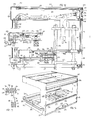
- - la figure 12 est une vue en coupe verticale d'un module à poste automatique ;
- - la figure 13 est une vue d'une partie de ce module, pour une autre condition d'un tiroir d'introduction ;
- - la figure 14 est une vue schématique perspective dudit module, certains organes ayant été enlevés ;
- - la figure 15 est une vue schématique en coupe de deux poutres à rainures.
- - Figure 1 is a schematic plan view of a rapid return module and a perpendicular or transverse module;
- - Figure 2 is a sectional view along line II-II of Figure 1, but on a larger scale;
- - Figure 3 is a bottom view of a workpiece pallet;
- - Figure 4 is a plan view of part of the second module of Figure 1, but on a larger scale;
- - Figure 5 is a sectional view along line VV of Figure 4;
- - Figure 6 is a sectional view along line VI-VI of Figure 4;
- - Figure 7 is a schematic plan view of a module manual assembly;
- - Figure 8 is an enlarged plan view of part of the module of Figure 7;
- - Figure 9 is a view similar to Figure 8, but for another condition;
- - Figure 10 is a sectional view along line XX of Figure 7;
- - Figure 11 is a view similar to Figure 8, but showing an actuating cylinder;
- - Figure 12 is a vertical sectional view of an automatic station module;
- - Figure 13 is a view of a part of this module, for another condition of an introduction drawer;
- - Figure 14 is a schematic perspective view of said module, some members having been removed;
- - Figure 15 is a schematic sectional view of two grooved beams.
Le module de retour rapide 21 (figure 1) ménage une voie 22 pour le déplacement d'une palette porte-pièce 23. La palette 23 comprend une plaque ou corps de palette 24 (figure 2) à configuration rectangulaire, par exemple carrée, limitée par un bord amont 25 (ou de droite comme vu par un observateur placé à l'avant de la machine), un bord aval ou de gauche 26, un bord avant 27 et un bord arrière 28. Sur la face inférieure 29 de la plaque 24, près des bords 27 et 28, des stries transversales ont été formées suivant deux bandes longitudinales 29 et 31 dont les extrémités, comme montré en 32 et 33, sont distantes des bords transversaux, ici le bord 25. Deux patins transversaux 34 et 35, de forme générale parallélépipédique, font saillie vers le bas par rapport à la face inférieure 36 de la plaque 24.The rapid return module 21 (FIG. 1) provides a
Sur la face inférieure 37 de chaque patin, par exemple le patin 34, sont présentes des stries métalliques formant des bandes transversales 38 et 39, de longueurs inégales, l'extrémité avant 41 de la bande 38 étant proche de la face verticale antérieure 42 du patin 34 et l'extrémité arrière 43 de la bande 39 proche de la face verticale 44 dudit patin, mais l'extrémité opposée 45 de la bande 38' est plus distante du plan longitudinal moyen 49 de la palette que l'extrémité 51 de la bande 39. Les bandes striées sur les patins sont à symétrie diagonale, c'est-à-dire que les bandes de même longueur sont adjacentes à des angles diagonalement opposés de la palette. On peut ainsi distinguer l'un des bords de la la palette du bord opposé et on tire parti de cette disposition pour la commande automatique du déplacement des palettes par coopération avec des capteurs que présente le fond des modules.On the
Chaque patin loge, dans sa partie centrale, trois sabots longitudinaux ou touches 521, 522, 523 montés indépendamment à rotation autour d'un même axe transversal 53 et dont la face inférieure présente un biseau, chacun des sabots pouvant prendre deux positions, l'une dans laquelle son extrémité en biseau fait saillie par rapport à la face inférieure 37 du patin et l'autre dans laquelle aucune partie du sabot ne fait saillie par rapport à ladite face inférieure.Each shoe houses, in its central part, three longitudinal shoes or keys 52 1 , 52 2 , 52 3 independently mounted for rotation about the same transverse axis 53 and the lower face of which has a bevel, each shoe can take two positions , one in which its beveled end projects with respect to the
Vers ses extrémités, chaque patin présente deux plots 56, 57, à contour rectangulaire, qui logent des billes de roulement ou billes de manutention respectivement 61, 62 faisant saillie par rapport aux faces inférieures 63, 64 des plots. De telles billes, bien connues en soi et fabriquées par exem- pie par SKF, ont une partie non visible placée dans un logement, l'intervalle entre la bille et la paroi du logement étant empli de très petites billes, de sorte que la rotation de la bille autour de son centre se fait pratiquement sans frottement. !Towards its ends, each shoe has two
La palette 23 repose par l'intermédiaire des billes 62, 62' de ses patins 34, 35, dans un chemin de roulement 65 ménagé sur la face supérieure 66 d'une barre 67 fixée sur le fond 68 du module 21 par des vis 60. L'entrainement de la palette 23 se fait par coopération de sa bande moletée ou striée 29 avec une courroie 69 à section transversale circulaire reposant sur des rouleaux 71 faisant saillie par rapport à la face interne 72 d'un rail antérieur 73 fixé sur le fond 68 du module 21 par des vis 74. C'est le poids de la palette 23 qui assure le contact de pression entre la bande striée 29 et la courroie 69 permettant l'entrainement. Le bord opposé 28 de la palette peut coopérer avec un redent 75 que présente la partie supérieure d'un rail postérieur 76 fixé sur le fond 68 par des vis 77. Le rail antérieur 73 présente également un redent 78 duquel le bord interne de la palette est en regard.The
Le brin 69 fait partie d'une courroie 81 disposée suivant un circuit fermé par son engagement dans les gorges respectives de poulies 82 et 83 à axe vertical prévues à l'extrémité antérieure droite 84 et à l'extrémité antérieure gauche 85 du module 21.The
La voie 22 du module 21 se prolonge par une voie 86 d'un module 87 dirigé d'une manière générale perpendiculairement au module 21. Le module 87 présente à la partie postérieure de son entrée une poulie 88 à axe vertical sur laquelle passe une courroie 93 disposée suivant un circuit fermé à deux brins parallèles 94 et 95 dont la longueur est substantiellement égale à la largeur du module 87, ledit circuit fermé étant défini par une seconde poulie 94' à axe vertical à deux gorges. Avant que l'extrémité de droite de la palette (comme considérée par un observateur se trouvant à l'avant de la machine dont font partie les modules 21 et 87), quitte le brin 69 de la courroie 81, son extrémité de gauche a, par le bord inférieur de son bord postérieur, pris contact avec le brin 95 de la courroie 93, situé au même niveau que le brin 69, de sorte que l'entrainement de la palette se poursuit sans discontinuité.The
Lorsque la palette 23 parvient à proximité de la paroi latérale 97 du module 87, elle est entraînée suivant un mouvement perpendiculaire au mouvement qu'elle avait jusqu'alors et cela par le brin 98 d'une courroie 99 disposée suivant un circuit fermé horizontal défini d'une part par la gorge inférieure de la poulie 94' et à son autre extrémité par passage dans la gorge inférieure d'une poulie à deux gorges 102, les conditions dans lesquelles se passe le changement de direction d'entrainement de la palette étant explicitées ci-après pour le changement de direction de la palette qui se produit à l'aval lorsque la palette passe de la voie 103, perpendiculaire à la voie 86,à la voie 104 du module 87'perpendiculaire à la voie 103, donc longitudinale.When the
Dans la voie 103, l'entrainement de la palette par le brin 98 de la courroie 99 se fait par coopération dudit brin avec les bandes striées 39' et 38' du patin 35 de ladite palette proches du bord 26 de celle-ci. La palette est supportée par le chemin de roulement 105 que présente une barre 106, transversale, fixée sur le fond 107 du module 87 et avec lequel coopèrent les billes 61, 62 de l'extrémité de droite de la palette.In
Lorsque la palette aborde le carrefour 108 entre les voies 103 et 104, au guidage de son mouvement contribue un aileron 109 que présente, en saillie vers le haut, une barre 111 prolongeant la barre 106 et qui coopère avec le patin 34 de la palette. Ladite barre, qui présente sur sa face supérieure un chemin de roulement 112 prolongeant le chemin de roulement 105, a une pente légèrement ascendante grâce à l'interposition, entre sa face inférieure 113 (figure 6) et le fond 107 du module, d'une rondelle 114 maintenue par une vis 115. La barre 111 présente à son extrémité une dénivellation ou gouttière 116 dans laquelle aboutit le chemin de roulement 112.When the pallet approaches the
Lorsqu'elle parvient au carrefour 108, sous l'effet d'entrainement du brin 98 de la courroie 99, le bord de droite 25 de la palette est légèrement soulevé par rapport à son bord de gauche, en raison de la pente ascendante du chemin de roulement 112, le bord de gauche 26 de la palette restant guidé dans le redent 110 que présente le rail transversal 100 : la face inférieure du plateau 24, en extrémité de course, avant que la bille 61 parvienne à la dénivella- tibn 116, surplombe un brin de courroie 117, au même niveau que le brin de courroie 95 ; lorsque la bille 61 tombe dans la dénivellation 116, la bande striée 29 vient en contact par un mouvement vertical, sous l'effet de la gravité, avec le brin de courroie 117 sans que le bord 27 de la palette ait heurté ledit brin. Le passage de l'entrainement dans le sens transversal, par coopération avec des bandes striées des patins, à un entrainement dans le sens longitudinal, par coopération avec des bandes striées perpendiculaires de la plaque, se fait donc dans les meilleures conditions.When it reaches the
Le brin de courroie 117 fait partie d'une courroie 118 comprenant un second brin parallèle 119, la courroie étant disposée suivant un circuit fermé entre, d'une part, la poulie à axe vertical 102 à deux gorges 91, 92, la gorge inférieure 92 recevant la courroie 99 et la gorge supérieure 91 recevant la courroie 118, et, d'autre part, une poulie 121, à une gorge, laquelle est calée sur l'arbre d'un moteur électrique 90.The
L'entrainement de la palette se fait alors suivant la voie 104 et au guidage de la palette pendant ce parcours sur le carrefour 108 contribue un aileron 122 faisant partie d'une barre 123 érigée sur le fond 107 et que prolonge une barre 124, la barre 123 et la barre 124 présentant sur leur face supérieure le chemin de roulement 125 avec lequel coopèrent les billes 62 et 62' portées par les plots 57 et 57' de la palette. Le brin de courroie 117 est supporté par les rouleaux 131 montés sur le rail 132, lequel présente une traversée 133 pour le passage de la courroie 118. Le contact de la face inférieure 36 du plateau de la palette le long de la bande striée 29, avec le brin 117 assure, sous l'effet du poids de la palette, et éventuellement de la pièce qu'elle porte, l'entrainement de ladite palette dans le sens marqué par la flèche 134, le bord opposé de la palette coopérant avec le redent 135 du.rail 136.The pallet is then driven along
A la sortie 137 du module 87, la palette est, pendant un court instant, entrainée, par sa partie amont ou de gauche, par le brin de courroie 117, tandis que sa partie de droite ou aval est en contact d'entraînement avec un brin de courroie 138 (figure 7) au même niveau que le brin 117, et qui fait partie d'une courroie 139 disposée suivant un circuit fermé défini notamment par une poulie 141 proche de l'entrée 142 du module 143 prévu pour l'assemblage manuel de pièces. La courroie 139 traverse le rail longitudinal 144 portant les rouleaux supportant le brin 138 par une ouverture 145 prévue dans ledit rail. L'autre brin 146 de la courroie 139 est guidé dans la gorge d'une poulie 147, calée sur l'arbre d'un moteur électrique, en abordant celle-ci par sa partie antérieure; la courroie passe sur une autre poulie 148 qu'elle aborde par sa partie postérieure, le plan des axes 149 et 151 des poulies étant parallèle à la direction longitudinale. La courroie passe ainsi sur une poulie 152 dont l'axe 153 est dans le plan longitudianl passant par l'axe 154 de la poulie 141, et la courroie se raccorde au brin avant 138, après avoir traversé un rail 154 prolongeant le rail 144 par une ouverture 155.At the
La poulie 148 est une poulie à deux gorges, la gorge inférieure 156 guidant une courroie 157, disposée suivant un circuit fermé, et à un niveau qui est inférieur au niveau de la courroie 139 et inférieur également à celui de la courroie 99 que comprend le module 87. La courroie 157 passe ensuite, dans le sens de sa circulation - alors que la description ci-dessus du circuit de la courroie 139 a été faite en sens contraire de la circulation de cette dernière - dans une seconde gorge 158 de la poulie 147 puis dans la gorge 159 d'une poulie 161 dont l'axe 162 est dans le même plan vertical que les axes 149 et 151. La courroie 157 comprend un brin 163 situé dans un plan transversal et qui, à son extrémité, traverse par une ouverture 164 un rail antérieur 165, après quoi la courroie 157 se prolonge par un brin 166, longitudinal, après passage sur une poulie 167 puis, après passage dans la gorge inférieure d'une poulie 168, à double gorge, par un brin 169, à nouveau transversal, par lequel elle regagne la poulie 148.
La gorge supérieure 171 de la poulie 168 sert au guidage d'une courroie 172 disposée suivant un circuit comprenant un brin antérieur 173 qui, par passage sur une poulie 174 à axe 175, se raccorde à un brin longitudinal 176 reposant sur des rouleaux portés par le rail longidutinal 165. Le circuit fermé de la courroie 172 est complémentairement défini par une poulie 178 dont l'axe 179 est dans le plan longitudinal passant par l'axe 175 de la poulie 174. La courroie 172 est dans le même plan horizontal supérieur que la courroie 139 qui est également-celui de la courroie 118, de la courroie 93 et de la courroie 81, ce qui a été symbolisé sur les dessins par le poché adopté pour représenter lesdites courroies.The
La poulie 174 est une poulie à deux gorges et dans la gorge inférieure de ladite poulie passe une courroie 182 à deux brins horizontaux 183 et 184, disposée en circuit fermé grâce à une poulie 185 montée à rotation autour d'un axe 186 dans le même plan transversal que l'axe 175. La courroie 182 est à un niveau intermédiaire, qui est celui de la courroie 99, comme schématisé par le poché interrompu adopté pour représenter lesdites courroies.The
La courroie 182 est supportée par son brin 184 par des rouleaux que porte un rail transversal 187. Celui-ci se raccorde à un rail longitudinal 188, lequel est dans le prolongement du rail 132 du module 87.The
La figure 8 montre une palette porte-pièce 23 ayant quitté le module 87 en étant entrainée par le brin 117 de courroie et ayant pénétré dans le module 143 entrainée par le brin 138 de la courroie 139. Au guidage de la palette 23 contribue un aileron 191 (figure 8) que présente la barre 192 à chemin de roulement 193 et dont est solidaire une barrette 194, perpendiculaire, présentant également un aileron 195 (figure 7).Figure 8 shows a
Le carrefour 196 entre la voie d'entrée 197 et la voie transversale 198 est équipé de deux goujons verticaux 199, 201, cylindriques, montés à rotation autour de leur axe et dont les parties supérieures présentent des échancrures définissant des plans verticaux diamétraux 202 et 203. Dans la condition montrée sur la figure 8, lesdits plans verticaux 202 et 203 sont alignés longitudinalement. La palette 23 est entrainée par le brin de courroie 138, roule par ses billes antérieures sur le chemin de roulement 193, est guidée par coopération de la face longitudinale 205 de son plot postérieur de droite 57 avec la face de'butée 202, puis par coopération de la face verticale antérieure de droite 205' contre l'aileron 211. Avant d'arriver au centre du carrefour, le bord de droite 25 de la palette est soulevé, comme expliqué ci-dessus en référence à la figure 6, puis la palette retombe par gravité de manière que les faces inférieures des plots 56 et 57 retombent sur le brin de courroie 163 mais la palette n'est pas entrainée par celle-ci en raison de la coopération par butée positive de la face 105 du plot avec la face de butée 203, de sorte que la palette poursuit son mouvement longitudinal, le guidage étant assuré par coopération du plot 56' avec l'aileron 191.The
Par contre, dans la condition montrée sur la figure 9, en laquelle les goujons 199 et 201 ont leurs plans verticaux 202 et 203 dirigés transversalement, la rotation desdits goujons ayant lieu après passage de l'un et l'autre des plots 57 et 57' devant le goujon 199, le plot 57 vient heurter la face verticale 203, ce qui empêche la poursuite de l'entrainement par le brin 138 de la courroie située au niveau supérieur et, par contre,'permet, après basculement et retombée, l'entrainement de la palette par le brin transversal 163 situé au niveau inférieur et qui coopère avec les bandes striées 61 et 62 des plots 56 et 57. Au début du mouvement, l'aileron 195 contribue au guidage de la palette dans son mouvement transversal. La courroie 103 exerce une action d'entraînement suivant seulement une très faible course pendant le court intervalle existant entre l'entrainement longitudinal et l'entrainement transversal assumés par la courroie 182. Elle a ainsi un rôle transitoire pour assurer le passage du carrefour. Après cette faible course transversale, la bande striée 38' du patin 35 prend contact avec le brin 184 de la courroie 182, au niveau intermédiaire, qui assure l'entrainement de la palette, celle-ci étant guidée par son bord opposé dans l'échancrure 212 ménagée dans le bord 213 du bloc rectangulaire 214.On the other hand, in the condition shown in FIG. 9, in which the
Dans la condition montrée sur la figure 9, le goujon 199 s'oppose par son plan de butée verticale 202 à l'arrivée d'autres palettes au carrefour 196.In the condition shown in FIG. 9, the
Pour leur actionnement, les goujons 199 et 201 sont solidaires de queues ou manivelles 215 et 216 qui sont attelées sur une bielle 217 dont l'extrémité 218 est reliée à l'organe mobile 219 d'un vérin 221.For their actuation, the
L'invention prévoit un moletage sur les faces d'extrémités longitudinales des patins dans leur partie adjacente à la face inférieure du plateau et qui, par coopération avec un brin de courroie situé au niveau supérieur, contribuent à l'entrainement de la palette.The invention provides a knurling on the longitudinal end faces of the pads in their part adjacent to the underside of the plate and which, by cooperation with a strand of belt located at the upper level, contribute to the drive of the pallet.
Lorsqu'une palette circule dans la voie longitudinale 222 prolongeant la voie d'entrée 197 du module 143, sous l'effet d'entrainement du brin de courroie 138,et qu'elle parvient au carrefour 223 avec la voie transversale 224 parallèle à la voie 198 mais adjacente à la paroi transversale de droite 225, l'effet du brin 169 de la courroie 157 qui s'exerce contre la bande striée 62 que présente la face inférieure du plot 51 a pour effet d'appliquer la tranche striée du patin contre la courroie 138, ce qui accroit l'effet d'entraînement de cette dernière sur la palette.When a pallet circulates in the
Une butée éclipsable 226 est prévue à la sortie de la voie 222 et qui vient en position opératoire lorsque l'ouvrière souhaite évacuer une ou plusieurs palettes de la voie longitudinale d'assemblage 227. On a ainsi la certitude que l'évacuation des palettes portant une pièce traitée dans le poste ne sera pas perturbée par la circulation de palettes circulant dans la voie 222. La poussée qu'exercent dans la voie 224, sur la palette parvenant au carrefour 223, les palettes qui suivent celle-ci ne peut qu'être favorable à l'entraînement de ladite palette aval par le brin 138.An
Dans chacun des modules, les courroies sont disposées suivant des circuits fermés de faible longueur. Chaque courroie a à assumer l'entraînement d'une palette ou d'un petit nombre de palettes. La résistance à l'avancement d'une palette est très faible en raison de son support par l'intermédiaire de billes. Chaque courroie est donc soumise à un effort de traction relativement petit. Elle peut être en un matériau habituel pour les courroies et assumer un service prolongé. Elle est avantageusment à section transversale circulaire.In each of the modules, the belts are arranged in closed circuits of short length. Each belt has to assume the drive of a pallet or a small number of pallets. The resistance to advancement of a pallet is very low due to its support by means of balls. Each belt is therefore subjected to a relatively small tensile force. She may be in a usual material for belts and assume an extended service. It is advantageously of circular cross section.
On se réfère maintenant aux figures 12 à 14 relatives à un poste de traitement automatique constituant un des modules de la machine. Ledit poste comporte un guichet 231 défini par deux traverses 232, 233 ménageant des coulisseaux 234 en regard l'un de l'autre pour l'introduction et la réception d'une palette, le mouvement vers l'avant de la palette étant limité par deux blocs de butée 235 et 236. L'extrémité d'un rail longitudinal 237 de roulement des palettes est.fixé à la traverse 232 et il y circule le bord antérieur 238 des palettes 239. Celles-ci sont entrainées par une courroie 241 à section circulaire qui coopère avec la bande striée longitudinale inférieure 242 adjacente au bord postérieur de la palette. En regard du guichet 231, et à un niveau inférieur à celui-ci, est disposé un tiroir 243 en forme de L, à deux branches, à savoir une branche horizontale 244 et une branche verticale 245. La branche verticale 245 est fixée à l'extrémité 246 de l'organe mobile 247 d'un vérin dont le corps 248 est fixé à la face inférieure 249 d'un profilé 251 en forme générale de omega avec un fond 252 de grande largeur se terminant par une rive longitudinale postérieure 253 et une rive longitudinale antérieure 254, l'une et l'autre en forme d'U. Un rail 255 supportant la courroie 241 est à l'avant de la rive postérieure 253 et il est ajouré pour permettre le passage de la branche horizontale 244 du tiroir 243. Ladite branche présente à sa partie antérieure une rainure à section rectangulaire 256 propre à recevoir les plots postérieurs 257 de la palette-239. Près de son attache à la branche verticale 245, la branche horizontale 244 présente un chemin de roulement 258.Reference is now made to FIGS. 12 to 14 relating to an automatic processing station constituting one of the modules of the machine. Said station comprises a
La figure 13 montre une palette qui, sous l'effet d'entrainement de la courroie 241, est parvenue face au guichet 231. Dans la dernière partie de son parcours, elle est soutenue par un dé 261 présentant un chemin de roulement 262 qui coopère avec les billes des plots antérieurs de la palette et qui est porté par une tige verticale 263, éclipsable.FIG. 13 shows a pallet which, under the driving effect of the
La palette étant parvenue en face du guichet 231, le vérin 248 est actionné. Les bords transversaux de la palette s'introduisent dans les coulisseaux 234, le bloc 261 étant alors éclipsé. La position de fin d'introduction est montrée sur la figure 12, le bord antérieur de la palette étant alors en butée contre les blocs 235 et 236. La palette, et la pièce qu'elle porte sont alors en position pour que la pièce soit traitée par un.outil qu'on a schématisé en 264. Dans cette position du tiroir 231, le chemin 256 du tiroir 243 prolonge le chemin ménagé par le rail longitudinal antérieur 237 du module de sorte qu'une palette arrivante 265 peut poursuivre son chemin au droit du guichet entrainée par la courroie 241, le dé 261 étant alors éclipsé.The pallet having reached the
Le poste automatique comprend, comme éléments d'ossature, au droit des traverses 232 et 233,deux poutres-transversales inférieures 271. C'est sur ces poutres transversales que sont assemblées, par boulonnage, les colonnes 273 traversant les traverses 232 et 233 par des trous 274, 275, 276, 277 que présentent celles-ci. Sur les poutres transversales 271 est fixée une poutre à rainures longitudinale inférieure 278 et sur les traverses 232 et 233, à l'extrémité avant de celles-ci, une poutre à rainures longitudinale 279, ainsi à hauteur du guichet 231 et régnant sur toute la lar--geur du module. Les poutres 278 et 279 servent à la fixation, à leurs extrémités, de deux joues 281 et 282 constituées chacune par une tôle en forme de C. Sur les joues 281, 282, vers la partie inférieure de celles-ci, sont fixés des fers en U dont l'un est visible en 283. Ce sont ces fers en U qui servent à l'enfichage du module sur les éléments de structure de la machine, à la manière 284 d'un tiroir. La branche inférieure de chaque U présente une encoche pour laisser passage au convoyeur constitué car le profile en omega et dont les extrémités sont fixées sur les fers en U 283.The automatic station comprises, as framework elements, in line with the
Entre les joues 281 et 282 sont interposées des poutres à rainures antérieures respectivement de sommet 285 et supérieure 286. A l'extrémité postérieure des poutres transversales 271 sont fixés, par boulonnage, des poteaux 287. A l'extrémité supérieure desdits poteaux est fixée une poutre à rainures longitudinale 288 ainsi qu'une tôle posté- ro-supérieure 289, à section en forme d'U, dont la branche supérieure 291 sert à la fixation d'une sixième poutre à rainures 292.Between the
La solidarisation du convoyeur 253 a lieu par l'intermédiaire de potelets 293 fixés à leur partie inférieure sur les poutres transversales 271. A la fixation du convoyeur contribue également une poutre longitudinale 294 prenant appui sur un cadre 295 traversé par les colonnes 273.The securing of the
Une poutre à rainures a la section montrée sur la figure 15. Elle est à contour général rectangulaire et présente sur une de ses grandes faces longitudinales 301 des rainures, au nombre de trois dans l'exemple représenté 302, 303, 304 et sur la face opposée, des rainures de même nombre mais de plus grande profondeur 305, 306, 307. L'association de deux telles poutres à rainures 308, 309 permet le montage de plaques 311 et leur maintien.A grooved beam has the section shown in FIG. 15. It has a generally rectangular outline and has grooves on one of its large
En présentant une plaque 311 avec son bord inférieur 312 au niveau de la face supérieure 313 de la poutre à rainure inférieure 309, il est possible d'engager ladite plaque dans la rainure 307 de la poutre à rainures supérieure 308. La plaque retombe ensuite, sous l'action de son propre poids, dans la rainure 304' de la poutre à rainures inférieure 309 pour aboutir à la condition montrée sur la figure 15.By presenting a
Les plaques engagées peuvent être, suivant le cas, des tôles ou bien des plaques transparentes comme en "plexiglas". Entre les poutres à rainures antérieures 279 et 286 on a ainsi mis en place deux vitres 311 et 312. Ces vitres peuvent coulisser horizontalement, ce qui permet l'accès à la partie du module observé et également de réaliser la continuité de la sépration entre l'intérieur du module et l'extérieur du module.Depending on the case, the engaged plates may be sheets or else transparent plates such as "plexiglass". Between the beams with
Entre la poutre à rainures inférieure 278 et la poutre à rainures 279 est montée une tôle 313 interdisant dans les conditions habituelles l'accès au personnel de l'espace situé en dessous du guichet 231.Between the lower
Entre la poutre à rainures antéro-supérieure 285 et la poutre immédiatement inférieure 286 a été montée une plaque d'acier 314 qui porte une batterie d'électro-distributeurs 315 avec des boutons d'actionnement montrés en 316. Ces boutons sont accessibles de l'extérieur mais protégés par des bandeaux 317 et 318 de matière plastique montés de manière amovible par clipsage sur les poutres à rainures respectivement 285 et 286. Lesdites poutres servent également au montage amovible d'une plaque transparente 319.Between the anterior-upper
La poutre à rainures 285 et la poutre à rainures postéro- supérieure 292 servent, par leurs rainures 328, 329, au montage de deux plaques transparentes 321 et 322 qui constituent le plafond 323 d'un boitier ou carter 324 logeant des dispositifs électro-pneumatiques. Des conducteurs ou conduits électriques ou pneumatiques 325 protégés dans le boitier 324 se prolongent dans des fourreaux 326 à.paroi 327 entourant les poteaux 287.The
Une telle organisation d'une part assure au personnel la sécurité maximale, d'autre part, permet à l'utilisateur d'adapter le module à l'utilisation précise qu'il souhaite, également assure au personnel le visibilité permettant le contrôle à tout instant du bon fonctionnement du module.Such an organization on the one hand ensures maximum security for the personnel, on the other hand, allows the user In order to adapt the module to the precise use they wish, it also provides staff with visibility allowing them to check at all times that the module is working properly.
Claims (31)
Priority Applications (1)
| Application Number | Priority Date | Filing Date | Title |
|---|---|---|---|
| AT83400419T ATE49366T1 (en) | 1982-03-05 | 1983-03-01 | ASSEMBLY OR MACHINING MACHINES FOR WORKPIECES. |
Applications Claiming Priority (2)
| Application Number | Priority Date | Filing Date | Title |
|---|---|---|---|
| FR8203757 | 1982-03-05 | ||
| FR8203757A FR2522566B2 (en) | 1982-03-05 | 1982-03-05 | BELT DRIVE DEVICE FOR PALLETS OF A MACHINE FOR ASSEMBLING OR MACHINING PARTS |
Publications (3)
| Publication Number | Publication Date |
|---|---|
| EP0088680A2 true EP0088680A2 (en) | 1983-09-14 |
| EP0088680A3 EP0088680A3 (en) | 1985-04-17 |
| EP0088680B1 EP0088680B1 (en) | 1990-01-10 |
Family
ID=9271676
Family Applications (1)
| Application Number | Title | Priority Date | Filing Date |
|---|---|---|---|
| EP83400419A Expired - Lifetime EP0088680B1 (en) | 1982-03-05 | 1983-03-01 | Workpiece assembly or processing machines |
Country Status (6)
| Country | Link |
|---|---|
| US (1) | US4513854A (en) |
| EP (1) | EP0088680B1 (en) |
| AT (1) | ATE49366T1 (en) |
| DE (1) | DE3381085D1 (en) |
| ES (1) | ES520343A0 (en) |
| FR (1) | FR2522566B2 (en) |
Cited By (4)
| Publication number | Priority date | Publication date | Assignee | Title |
|---|---|---|---|---|
| FR2564075A1 (en) * | 1984-05-16 | 1985-11-15 | Villejuif Etudes Indles | Flexible and modular conveying installation for components for mounting or for machining |
| FR2589134A1 (en) * | 1985-10-29 | 1987-04-30 | Prodel Jacques | Installation for assembling and/or machining components carried by pallets, and pallet forming part of this installation |
| EP0223683A1 (en) * | 1985-10-29 | 1987-05-27 | Jacques Prodel | Apparatus for the assembly and/or application of parts carried by pallets, and pallet for such an apparatus |
| FR2611556A1 (en) * | 1987-03-06 | 1988-09-09 | Telemecanique Electrique | WORKING STATION BETWEEN A PATHWAY OF PARTS AND A PERPENDICULAR EVACUATION PATH |
Families Citing this family (12)
| Publication number | Priority date | Publication date | Assignee | Title |
|---|---|---|---|---|
| FR2547520B1 (en) * | 1983-06-17 | 1985-10-11 | Prodel Maurice | MODULAR INSTALLATION FOR ASSEMBLING AND / OR MACHINING PARTS, WITH KEYBOARD-DISPLAY DEVICES AT EACH STATION |
| AT392050B (en) * | 1984-02-06 | 1991-01-10 | Sticht Walter | MANUFACTURING SYSTEM WITH SEVERAL SINGLE STATIONS |
| AT397779B (en) * | 1989-03-08 | 1994-06-27 | Sticht Fertigungstech Stiwa | MANUFACTURING SYSTEM FOR MACHINING AND ASSEMBLING COMPONENTS |
| JPH049854U (en) * | 1990-05-16 | 1992-01-28 | ||
| IL96799A (en) * | 1990-12-27 | 1995-11-27 | Fuselage Eng Services | Aircraft fuselage construction including food carrier |
| FR2679164B1 (en) * | 1991-07-17 | 1993-10-15 | Telemecanique | DEVICE FOR MOVING PARTS FROM ONE STATION TO ANOTHER ALONG A LINE OF THEIR PROCESSING. |
| DE4129294A1 (en) * | 1991-09-03 | 1993-03-04 | Protech Automation Gmbh | DUPLEX CONVEYOR LINE |
| US5351801A (en) * | 1993-06-07 | 1994-10-04 | Board Of Regents - Univ. Of Nebraska | Automated laboratory conveyor system |
| US6533101B2 (en) | 1998-06-24 | 2003-03-18 | Asyst Technologies, Inc. | Integrated transport carrier and conveyor system |
| US6223886B1 (en) | 1998-06-24 | 2001-05-01 | Asyst Technologies, Inc. | Integrated roller transport pod and asynchronous conveyor |
| US6435330B1 (en) * | 1998-12-18 | 2002-08-20 | Asyai Technologies, Inc. | In/out load port transfer mechanism |
| US6308818B1 (en) | 1999-08-02 | 2001-10-30 | Asyst Technologies, Inc. | Transport system with integrated transport carrier and directors |
Citations (7)
| Publication number | Priority date | Publication date | Assignee | Title |
|---|---|---|---|---|
| AT320523B (en) * | 1971-01-27 | 1975-02-10 | Armin Kleiber | Transport system with lengthways and crossways movable pallets |
| US3931882A (en) * | 1973-05-04 | 1976-01-13 | Ossbahr C | Modular article conveyor |
| US4014428A (en) * | 1973-05-04 | 1977-03-29 | Ossbahr C | Modular article conveyor |
| DE2644136A1 (en) * | 1976-09-30 | 1978-04-06 | Bosch Gmbh Robert | Conveyor system for articles projecting downwards - with carriers moved by one side belt and sliding on track |
| DE2752268A1 (en) * | 1977-11-23 | 1979-06-07 | Hellmut Scheffler | Workpiece handling and conveying installation - has carriages with rollers running on rails and bevelled edges engaging clamping rails when carriage is raised |
| GB2040244A (en) * | 1978-12-27 | 1980-08-28 | Prodel M | Conveyor machine with stations for assembling and/or machining workpieces |
| EP0050080A2 (en) * | 1980-10-14 | 1982-04-21 | Maurice Prodel | Assembling and/or machining installation for workpieces supported on travelling pallets which can be stopped |
Family Cites Families (16)
| Publication number | Priority date | Publication date | Assignee | Title |
|---|---|---|---|---|
| GB416968A (en) * | 1933-03-20 | 1934-09-20 | Jacques Rome | Improvements in and relating to garages for automobiles and the like |
| US2652919A (en) * | 1949-11-07 | 1953-09-22 | Cutler Hammer Inc | Drive system for conveyers |
| US2837223A (en) * | 1953-11-03 | 1958-06-03 | Wolff Ivan | Automobile parking apparatus |
| US3315778A (en) * | 1956-10-17 | 1967-04-25 | Kenhos Dev Pool | Machine tools |
| US3221754A (en) * | 1962-12-05 | 1965-12-07 | Toledo Scale Corp | Dishwashing machines |
| US3313393A (en) * | 1963-06-17 | 1967-04-11 | Standard Tool & Mfg Company | Pallet transfer device |
| US3272240A (en) * | 1963-11-15 | 1966-09-13 | Roth Wilfred | Container filling transfer mechanism |
| US3530571A (en) * | 1967-12-15 | 1970-09-29 | Cincinnati Milacron Inc | Manufacturing system |
| FR2068731B1 (en) * | 1969-10-31 | 1974-08-09 | Villemaud Jean | |
| DE2401503C3 (en) * | 1974-01-12 | 1978-12-21 | Cross Europa-Werk Gmbh, 7317 Wendlingen | Transfer device for workpiece carriers at the transfer stations of a transfer line |
| NL176841C (en) * | 1975-03-04 | 1985-06-17 | Philips Nv | TRANSPORTATION DEVICE FOR TEST SAMPLE CARRERS, AND THESE CARRIERS. |
| IT1034819B (en) * | 1975-04-03 | 1979-10-10 | Situno Holding Sa | CROSS TRANSPORT UNIT PARTICULARLY SUITABLE FOR THE TRANSPORT OR SORTING OF NEWSPAPERS, MAGAZINES AND OTHER OVERLAPPED ARTICLES |
| DE2518689C3 (en) * | 1975-04-26 | 1981-07-09 | Friedrich Wilhelm 8900 Augsburg Ortmann | Workpiece transport device for transfer lines with a square plan |
| CH596062A5 (en) * | 1976-01-16 | 1978-02-28 | Lanco Ag | |
| DE2710180A1 (en) * | 1977-03-09 | 1978-09-14 | Will E C H Gmbh & Co | CONVEYOR DEVICE FOR STACKING OBJECTS |
| FR2417238A7 (en) * | 1978-02-14 | 1979-09-07 | Bibonne Christian | Moving roadway toy for model cars - has flat belts to form course and driven by electric motor and gearing with transfers between belts |
-
1982
- 1982-03-05 FR FR8203757A patent/FR2522566B2/en not_active Expired
-
1983
- 1983-03-01 DE DE8383400419T patent/DE3381085D1/en not_active Expired - Lifetime
- 1983-03-01 AT AT83400419T patent/ATE49366T1/en not_active IP Right Cessation
- 1983-03-01 EP EP83400419A patent/EP0088680B1/en not_active Expired - Lifetime
- 1983-03-03 US US06/471,852 patent/US4513854A/en not_active Expired - Lifetime
- 1983-03-04 ES ES520343A patent/ES520343A0/en active Granted
Patent Citations (7)
| Publication number | Priority date | Publication date | Assignee | Title |
|---|---|---|---|---|
| AT320523B (en) * | 1971-01-27 | 1975-02-10 | Armin Kleiber | Transport system with lengthways and crossways movable pallets |
| US3931882A (en) * | 1973-05-04 | 1976-01-13 | Ossbahr C | Modular article conveyor |
| US4014428A (en) * | 1973-05-04 | 1977-03-29 | Ossbahr C | Modular article conveyor |
| DE2644136A1 (en) * | 1976-09-30 | 1978-04-06 | Bosch Gmbh Robert | Conveyor system for articles projecting downwards - with carriers moved by one side belt and sliding on track |
| DE2752268A1 (en) * | 1977-11-23 | 1979-06-07 | Hellmut Scheffler | Workpiece handling and conveying installation - has carriages with rollers running on rails and bevelled edges engaging clamping rails when carriage is raised |
| GB2040244A (en) * | 1978-12-27 | 1980-08-28 | Prodel M | Conveyor machine with stations for assembling and/or machining workpieces |
| EP0050080A2 (en) * | 1980-10-14 | 1982-04-21 | Maurice Prodel | Assembling and/or machining installation for workpieces supported on travelling pallets which can be stopped |
Cited By (6)
| Publication number | Priority date | Publication date | Assignee | Title |
|---|---|---|---|---|
| FR2564075A1 (en) * | 1984-05-16 | 1985-11-15 | Villejuif Etudes Indles | Flexible and modular conveying installation for components for mounting or for machining |
| FR2589134A1 (en) * | 1985-10-29 | 1987-04-30 | Prodel Jacques | Installation for assembling and/or machining components carried by pallets, and pallet forming part of this installation |
| EP0223683A1 (en) * | 1985-10-29 | 1987-05-27 | Jacques Prodel | Apparatus for the assembly and/or application of parts carried by pallets, and pallet for such an apparatus |
| FR2597450A2 (en) * | 1985-10-29 | 1987-10-23 | Prodel Jacques | Installation for the assembly and/or the machining of pieces carried by pallets and pallet forming part of this installation |
| US4832171A (en) * | 1985-10-29 | 1989-05-23 | Prodel Jacques M | Installation for assembling and/or machining parts carried on pallets, and a pallet forming a part of said installation |
| FR2611556A1 (en) * | 1987-03-06 | 1988-09-09 | Telemecanique Electrique | WORKING STATION BETWEEN A PATHWAY OF PARTS AND A PERPENDICULAR EVACUATION PATH |
Also Published As
| Publication number | Publication date |
|---|---|
| DE3381085D1 (en) | 1990-02-15 |
| ES8404221A1 (en) | 1984-05-01 |
| EP0088680B1 (en) | 1990-01-10 |
| EP0088680A3 (en) | 1985-04-17 |
| FR2522566B2 (en) | 1986-06-13 |
| US4513854A (en) | 1985-04-30 |
| FR2522566A2 (en) | 1983-09-09 |
| ES520343A0 (en) | 1984-05-01 |
| ATE49366T1 (en) | 1990-01-15 |
Similar Documents
| Publication | Publication Date | Title |
|---|---|---|
| EP0088680B1 (en) | Workpiece assembly or processing machines | |
| EP0050080B1 (en) | Assembling and/or machining installation for workpieces supported on travelling pallets which can be stopped | |
| FR2832654A1 (en) | Postal package conveyor sorting objects according to shape and size has side barrier with opening that allows through articles of permitted size | |
| EP2020388B2 (en) | Mobile troubleshooting platform for automated storage warehouse | |
| EP0527689B1 (en) | Linear conveyor device with free supporting trays | |
| FR2524089A1 (en) | LINEAR SLIDE BEARING AND LINEAR SLIDE TABLE EQUIPPED WITH SUCH BEARING | |
| FR2535293A1 (en) | METHOD AND INSTALLATION FOR STORING AUTOMATED HANDLING OBJECTS | |
| EP0738675B1 (en) | Storage device with mobile wagons having inclined frames | |
| FR2588284A1 (en) | RECTILINE MACHINE WITH A DISPLACABLE TROLLEY DEVICE IN A MAINTENANCE POSITION | |
| FR2675791A1 (en) | Transfer machine in the form of a travelling bridge for a bar stock material stores | |
| FR2621567A1 (en) | Installation for handling containers in the hold of a fishing vessel | |
| EP1270048A1 (en) | Rack with skis in an inclined position | |
| FR2491897A1 (en) | Assembly installation using circulating pallets - uses coding system to control movement of pallets which are frictionally advanced by conveyor belt | |
| FR2541974A1 (en) | Module for circulating workpiece-carrying pallets for a flexible machining or assembly workshop and flexible workshop comprising such modules | |
| FR2512723A1 (en) | Assembly installation using circulating pallets - uses coding system to control movement of pallets which are frictionally advanced by conveyor belt | |
| EP1801023A1 (en) | Storage container with drawers | |
| FR2699897A1 (en) | Storage and unloading unit for articles in boxes, pallets or packages | |
| EP0165918A1 (en) | Devices for the automatic distribution of products and a warehouse devised with the aid of such devices | |
| FR2687612A1 (en) | DEVICE FOR INSERTING A PRODUCT IN AN ENVELOPE, PARTICULARLY A LETTER ENVELOPE. | |
| FR2703284A1 (en) | Moving gantry with buried rails | |
| FR2545398A1 (en) | Installation for assembling and/or machining components carried by immobilisable circulating pallets | |
| BE547931A (en) | ||
| FR2966137A1 (en) | Line for stamping blanks of sheet for realizing parts of body of motor vehicle, has linear conveying system along which storing stations of blanks of sheet are arranged and extending along transverse axis perpendicular to longitudinal axis | |
| FR2510527A1 (en) | Feed for stocking articles between work positions - has separate vertically moving chain sections loading and unloading supports | |
| FR1278789A (en) | Improvements to installations for the automatic garage of vehicles and similar operations |
Legal Events
| Date | Code | Title | Description |
|---|---|---|---|
| PUAI | Public reference made under article 153(3) epc to a published international application that has entered the european phase |
Free format text: ORIGINAL CODE: 0009012 |
|
| AK | Designated contracting states |
Designated state(s): AT BE CH DE GB IT LI LU NL SE |
|
| PUAL | Search report despatched |
Free format text: ORIGINAL CODE: 0009013 |
|
| AK | Designated contracting states |
Designated state(s): AT BE CH DE GB IT LI LU NL SE |
|
| 17P | Request for examination filed |
Effective date: 19851016 |
|
| 17Q | First examination report despatched |
Effective date: 19870206 |
|
| GRAA | (expected) grant |
Free format text: ORIGINAL CODE: 0009210 |
|
| RAP1 | Party data changed (applicant data changed or rights of an application transferred) |
Owner name: PRODEL, JACQUES |
|
| RIN1 | Information on inventor provided before grant (corrected) |
Inventor name: PRODEL, JACQUES Inventor name: PRODEL, MAURICE |
|
| AK | Designated contracting states |
Kind code of ref document: B1 Designated state(s): AT BE CH DE GB IT LI LU NL SE |
|
| REF | Corresponds to: |
Ref document number: 49366 Country of ref document: AT Date of ref document: 19900115 Kind code of ref document: T |
|
| REF | Corresponds to: |
Ref document number: 3381085 Country of ref document: DE Date of ref document: 19900215 |
|
| GBT | Gb: translation of ep patent filed (gb section 77(6)(a)/1977) | ||
| ITF | It: translation for a ep patent filed |
Owner name: MODIANO & ASSOCIATI S.R.L. |
|
| PLBE | No opposition filed within time limit |
Free format text: ORIGINAL CODE: 0009261 |
|
| STAA | Information on the status of an ep patent application or granted ep patent |
Free format text: STATUS: NO OPPOSITION FILED WITHIN TIME LIMIT |
|
| 26N | No opposition filed | ||
| ITTA | It: last paid annual fee | ||
| EPTA | Lu: last paid annual fee | ||
| EAL | Se: european patent in force in sweden |
Ref document number: 83400419.4 |
|
| REG | Reference to a national code |
Ref country code: GB Ref legal event code: IF02 |
|
| PGFP | Annual fee paid to national office [announced via postgrant information from national office to epo] |
Ref country code: GB Payment date: 20020227 Year of fee payment: 20 |
|
| PGFP | Annual fee paid to national office [announced via postgrant information from national office to epo] |
Ref country code: CH Payment date: 20020325 Year of fee payment: 20 |
|
| PGFP | Annual fee paid to national office [announced via postgrant information from national office to epo] |
Ref country code: DE Payment date: 20020326 Year of fee payment: 20 Ref country code: BE Payment date: 20020326 Year of fee payment: 20 |
|
| PGFP | Annual fee paid to national office [announced via postgrant information from national office to epo] |
Ref country code: AT Payment date: 20020327 Year of fee payment: 20 |
|
| PGFP | Annual fee paid to national office [announced via postgrant information from national office to epo] |
Ref country code: SE Payment date: 20020328 Year of fee payment: 20 |
|
| PGFP | Annual fee paid to national office [announced via postgrant information from national office to epo] |
Ref country code: NL Payment date: 20020329 Year of fee payment: 20 |
|
| PGFP | Annual fee paid to national office [announced via postgrant information from national office to epo] |
Ref country code: LU Payment date: 20020410 Year of fee payment: 20 |
|
| PG25 | Lapsed in a contracting state [announced via postgrant information from national office to epo] |
Ref country code: LI Free format text: LAPSE BECAUSE OF EXPIRATION OF PROTECTION Effective date: 20030228 Ref country code: GB Free format text: LAPSE BECAUSE OF EXPIRATION OF PROTECTION Effective date: 20030228 Ref country code: CH Free format text: LAPSE BECAUSE OF EXPIRATION OF PROTECTION Effective date: 20030228 |
|
| PG25 | Lapsed in a contracting state [announced via postgrant information from national office to epo] |
Ref country code: NL Free format text: LAPSE BECAUSE OF EXPIRATION OF PROTECTION Effective date: 20030301 Ref country code: LU Free format text: LAPSE BECAUSE OF EXPIRATION OF PROTECTION Effective date: 20030301 Ref country code: AT Free format text: LAPSE BECAUSE OF EXPIRATION OF PROTECTION Effective date: 20030301 |
|
| REG | Reference to a national code |
Ref country code: GB Ref legal event code: PE20 Effective date: 20030228 |
|
| REG | Reference to a national code |
Ref country code: CH Ref legal event code: PL |
|
| BE20 | Be: patent expired |
Owner name: *PRODEL JACQUES Effective date: 20030301 |
|
| NLV7 | Nl: ceased due to reaching the maximum lifetime of a patent | ||
| EUG | Se: european patent has lapsed |