EP0088680A2 - Montage- oder Bearbeitungsmaschinen für Werkstücke - Google Patents
Montage- oder Bearbeitungsmaschinen für Werkstücke Download PDFInfo
- Publication number
- EP0088680A2 EP0088680A2 EP83400419A EP83400419A EP0088680A2 EP 0088680 A2 EP0088680 A2 EP 0088680A2 EP 83400419 A EP83400419 A EP 83400419A EP 83400419 A EP83400419 A EP 83400419A EP 0088680 A2 EP0088680 A2 EP 0088680A2
- Authority
- EP
- European Patent Office
- Prior art keywords
- pallet
- module
- belt
- installation according
- transverse
- Prior art date
- Legal status (The legal status is an assumption and is not a legal conclusion. Google has not performed a legal analysis and makes no representation as to the accuracy of the status listed.)
- Granted
Links
- 238000012545 processing Methods 0.000 title description 2
- 238000003754 machining Methods 0.000 claims abstract description 3
- 238000009434 installation Methods 0.000 claims abstract 23
- 230000000694 effects Effects 0.000 claims description 9
- 238000012549 training Methods 0.000 claims description 6
- 239000002184 metal Substances 0.000 claims description 4
- 229910052751 metal Inorganic materials 0.000 claims description 4
- 238000005096 rolling process Methods 0.000 claims description 4
- 230000001174 ascending effect Effects 0.000 claims description 3
- 230000001052 transient effect Effects 0.000 claims description 2
- 238000006073 displacement reaction Methods 0.000 claims 2
- 240000008042 Zea mays Species 0.000 description 4
- 239000000463 material Substances 0.000 description 4
- 235000000396 iron Nutrition 0.000 description 3
- 230000009471 action Effects 0.000 description 2
- 238000013459 approach Methods 0.000 description 2
- 230000008901 benefit Effects 0.000 description 2
- 230000008859 change Effects 0.000 description 2
- 230000005484 gravity Effects 0.000 description 2
- 229920003023 plastic Polymers 0.000 description 2
- 239000004033 plastic Substances 0.000 description 2
- 230000000284 resting effect Effects 0.000 description 2
- 238000011144 upstream manufacturing Methods 0.000 description 2
- VVQNEPGJFQJSBK-UHFFFAOYSA-N Methyl methacrylate Chemical compound COC(=O)C(C)=C VVQNEPGJFQJSBK-UHFFFAOYSA-N 0.000 description 1
- 229920005372 Plexiglas® Polymers 0.000 description 1
- 229910000831 Steel Inorganic materials 0.000 description 1
- 230000005540 biological transmission Effects 0.000 description 1
- 239000004020 conductor Substances 0.000 description 1
- 239000000470 constituent Substances 0.000 description 1
- 230000002349 favourable effect Effects 0.000 description 1
- PCHJSUWPFVWCPO-UHFFFAOYSA-N gold Chemical compound [Au] PCHJSUWPFVWCPO-UHFFFAOYSA-N 0.000 description 1
- 239000010931 gold Substances 0.000 description 1
- 229910052737 gold Inorganic materials 0.000 description 1
- 238000003780 insertion Methods 0.000 description 1
- 230000037431 insertion Effects 0.000 description 1
- 238000012423 maintenance Methods 0.000 description 1
- 210000000056 organ Anatomy 0.000 description 1
- 230000008520 organization Effects 0.000 description 1
- 230000009467 reduction Effects 0.000 description 1
- 238000000926 separation method Methods 0.000 description 1
- 238000007493 shaping process Methods 0.000 description 1
- 239000010959 steel Substances 0.000 description 1
- 230000007704 transition Effects 0.000 description 1
Images


Classifications
-
- B—PERFORMING OPERATIONS; TRANSPORTING
- B23—MACHINE TOOLS; METAL-WORKING NOT OTHERWISE PROVIDED FOR
- B23Q—DETAILS, COMPONENTS, OR ACCESSORIES FOR MACHINE TOOLS, e.g. ARRANGEMENTS FOR COPYING OR CONTROLLING; MACHINE TOOLS IN GENERAL CHARACTERISED BY THE CONSTRUCTION OF PARTICULAR DETAILS OR COMPONENTS; COMBINATIONS OR ASSOCIATIONS OF METAL-WORKING MACHINES, NOT DIRECTED TO A PARTICULAR RESULT
- B23Q7/00—Arrangements for handling work specially combined with or arranged in, or specially adapted for use in connection with, machine tools, e.g. for conveying, loading, positioning, discharging, sorting
- B23Q7/14—Arrangements for handling work specially combined with or arranged in, or specially adapted for use in connection with, machine tools, e.g. for conveying, loading, positioning, discharging, sorting co-ordinated in production lines
- B23Q7/1426—Arrangements for handling work specially combined with or arranged in, or specially adapted for use in connection with, machine tools, e.g. for conveying, loading, positioning, discharging, sorting co-ordinated in production lines with work holders not rigidly fixed to the transport devices
- B23Q7/1447—Arrangements for handling work specially combined with or arranged in, or specially adapted for use in connection with, machine tools, e.g. for conveying, loading, positioning, discharging, sorting co-ordinated in production lines with work holders not rigidly fixed to the transport devices using endless conveyors
- B23Q7/1452—Arrangements for handling work specially combined with or arranged in, or specially adapted for use in connection with, machine tools, e.g. for conveying, loading, positioning, discharging, sorting co-ordinated in production lines with work holders not rigidly fixed to the transport devices using endless conveyors comprising load-supporting surfaces
-
- B—PERFORMING OPERATIONS; TRANSPORTING
- B65—CONVEYING; PACKING; STORING; HANDLING THIN OR FILAMENTARY MATERIAL
- B65G—TRANSPORT OR STORAGE DEVICES, e.g. CONVEYORS FOR LOADING OR TIPPING, SHOP CONVEYOR SYSTEMS OR PNEUMATIC TUBE CONVEYORS
- B65G35/00—Mechanical conveyors not otherwise provided for
- B65G35/06—Mechanical conveyors not otherwise provided for comprising a load-carrier moving along a path, e.g. a closed path, and adapted to be engaged by any one of a series of traction elements spaced along the path
Definitions
- the invention relates to improvements to machines for assembling and / or machining parts.
- the invention is characterized by the fact that, for driving the pallets, a multiplicity of belts is used in a module, in principle each assigned to a straight course in one direction, the driving of the multiple belts of a module being however ensured from a single electric motor, pulleys with several grooves ensuring, if necessary, the transmission of the movement of a belt to a other belt.
- the invention also provides for shaping the underside of a pallet so as to be able to cooperate with the belts along three determined levels, one of the levels of the belts corresponding to the drive in the longitudinal direction, that is to say in parallel on the front face of the machine, the other level to the drive in the perpendicular or transverse direction, and a third level being provided to facilitate the passage from a drive in one direction to a drive in the perpendicular direction by a drive transient, for example transverse.
- the invention is further characterized by the application, to ensure the support and mobility of the pallets, of rolling or handling balls, known per se, allowing progression on at least one track provided on the bottom of the module.
- the invention provides for the use of belts with circular cross-section, made of a usual material for belts.
- such a belt cooperates with a banded region with ridges on the underside of the pallet.
- the invention advantageously applies to a palette of type comprising, on the underside of the plate, pads carrying coding members and at the ends of which are provided pads.
- the three training levels are then determined by the lower faces of the plate, the pads and the studs, respectively.
- the handling balls are housed in the studs.
- striated parts for the purpose of identifying or locating pallets by forming striations on a metal strip attached to the underside of a plastic pad and by providing striated metal strips of lengths. different for one side and the opposite side of a pallet.
- the rapid return module 21 provides a channel 22 for the movement of a workpiece pallet 23.
- the pallet 23 comprises a plate or pallet body 24 (FIG. 2) with a rectangular configuration, for example square, limited by an upstream edge 25 (or right as seen by an observer placed at the front of the machine), a downstream or left edge 26, a front edge 27 and a rear edge 28.
- Two transverse pads 34 and 35 of generally parallelepiped shape, protrude downward relative to the underside 36 of the plate 24.
- each pad for example the pad 34
- the striated strips on the pads are diagonally symmetrical, that is to say that the strips of the same length are adjacent to diagonally opposite angles of the pallet. We can thus distinguish one of the edges of the pallet from the opposite edge and we take advantage of this arrangement for the automatic control of the movement of the pallets by cooperation with sensors presented by the bottom of the modules.
- Each shoe houses, in its central part, three longitudinal shoes or keys 52 1 , 52 2 , 52 3 independently mounted for rotation about the same transverse axis 53 and the lower face of which has a bevel, each shoe can take two positions , one in which its beveled end projects with respect to the underside 37 of the shoe and the other in which no part of the shoe projects with respect to said bottom face.
- each shoe has two studs 56, 57, of rectangular outline, which house rolling balls or handling balls respectively 61, 62 projecting with respect to the lower faces 63, 64 of the studs.
- Such balls well known per se and manufactured for example by SKF, have an invisible part placed in a housing, the gap between the ball and the wall of the housing. being filled with very small balls, so that the rotation of the ball around its center is practically without friction. !
- the pallet 23 rests by means of the balls 62, 62 'of its pads 34, 35, in a raceway 65 formed on the upper face 66 of a bar 67 fixed to the bottom 68 of the module 21 by screws 60
- the pallet 23 is driven by the cooperation of its knurled or striated strip 29 with a belt 69 of circular cross section resting on rollers 71 projecting from the internal face 72 of an anterior rail 73 fixed on the bottom 68 of the module 21 by screws 74. It is the weight of the pallet 23 which ensures the pressure contact between the ribbed strip 29 and the belt 69 allowing the drive.
- the opposite edge 28 of the pallet can cooperate with a recess 75 which has the upper part of a rear rail 76 fixed to the bottom 68 by screws 77.
- the front rail 73 also has a recess 78 from which the internal edge of the pallet is opposite.
- the strand 69 is part of a belt 81 disposed in a closed circuit by its engagement in the respective grooves of pulleys 82 and 83 with a vertical axis provided at the right front end 84 and at the left front end 85 of the module 21.
- the track 22 of the module 21 is extended by a track 86 of a module 87 directed generally perpendicularly to the module 21.
- the module 87 has at the rear part of its inlet a pulley 88 with a vertical axis over which passes a belt 93 arranged in a closed circuit with two parallel strands 94 and 95, the length of which is substantially equal to the width of the module 87, said closed circuit being defined by a second pulley 94 'with a vertical axis with two grooves.
- the drive of the pallet by the strand 98 of the belt 99 is done by cooperation of said strand with the striated strips 39 ′ and 38 ′ of the shoe 35 of said pallet close to the edge 26 of the latter.
- the pallet is supported by the raceway 105 which has a transverse bar 106, fixed on the bottom 107 of the module 87 and with which the balls 61, 62 of the right end of the pallet cooperate.
- the guiding of its movement contributes a fin 109 which has, projecting upwards, a bar 111 extending the bar 106 and which cooperates with the pad 34 of the pallet.
- Said bar which has on its upper face a raceway 112 extending the raceway 105, has a slightly ascending slope thanks to the interposition, between its lower face 113 ( Figure 6) and the bottom 107 of the module, of a washer 114 held by a screw 115.
- the bar 111 has at its end a drop or gutter 116 in which the raceway 112 ends.
- the belt strand 117 is part of a belt 118 comprising a second parallel strand 119, the belt being arranged in a closed circuit between, on the one hand, the pulley with vertical axis 102 with two grooves 91, 92, the lower groove 92 receiving the belt 99 and the upper groove 91 receiving the belt 118, and, on the other hand, a pulley 121, with a groove, which is wedged on the shaft of an electric motor 90.
- the pallet is then driven along track 104 and the guide of the pallet during this course on the crossroad 108 contributes a fin 122 forming part of a bar 123 erected on the bottom 107 and which is extended by a bar 124, the bar 123 and bar 124 having on their upper face the raceway 125 with the which cooperate the balls 62 and 62 'carried by the pads 57 and 57' of the pallet.
- the belt strand 117 is supported by the rollers 131 mounted on the rail 132, which has a passage 133 for the passage of the belt 118.
- the pallet is, for a short time, driven, by its upstream or left part, by the belt strand 117, while its right or downstream part is in drive contact with a belt strand 138 (FIG. 7) at the same level as strand 117, and which is part of a belt 139 arranged in a closed circuit defined in particular by a pulley 141 near the inlet 142 of the module 143 provided for assembly parts manual.
- the belt 139 crosses the longitudinal rail 144 carrying the rollers supporting the strand 138 through an opening 145 provided in said rail.
- the other strand 146 of the belt 139 is guided in the groove of a pulley 147, wedged on the shaft of an electric motor, approaching the latter by its front part; the belt passes over another pulley 148 which it approaches via its rear part, the plane of the axes 149 and 151 of the pulleys being parallel to the longitudinal direction.
- the belt thus passes over a pulley 152 whose axis 153 is in the longitudinal plane passing through the axis 154 of the pulley 141, and the belt is connected to the front strand 138, after having crossed a rail 154 extending the rail 144 by an opening 155.
- Pulley 148 is a pulley with two grooves, the lower groove 156 guiding a belt 157, arranged in a closed circuit, and at a level which is lower than the level of the belt 139 and also lower than that of the belt 99 which the module 87 includes.
- the belt 157 then passes, in the direction of its circulation - while the above description of the circuit of the belt 139 has been made in the direction contrary to the circulation of the latter - in a second groove 158 of the pulley 147 then in the groove 159 of a pulley 161 whose axis 162 is in the same vertical plane as the axes 149 and 151.
- the belt 157 comprises a strand 163 situated in a transverse plane and which, at its end, passes through an opening 164 an anterior rail 165, after which the belt 157 is extended by a strand 166, longitudinal, after passing over a pulley 167 then, after passing through the lower groove of a pulley 168, with double groove, by a strand 169, again transverse, by which it returns to pulley 148.
- the upper groove 171 of the pulley 168 is used to guide a belt 172 arranged in a circuit comprising a front strand 173 which, by passing over a pulley 174 with axis 175, is connected to a longitudinal strand 176 resting on rollers carried by the longitudinal rail 165.
- the closed circuit of the belt 172 is additionally defined by a pulley 178 whose axis 179 is in the longitudinal plane passing through the axis 175 of the pulley 174.
- the belt 172 is in the same upper horizontal plane that the belt 139 which is also that of the belt 118, of the belt 93 and of the belt 81, which has been symbolized in the drawings by the poach adopted to represent said belts.
- the pulley 174 is a pulley with two grooves and in the lower groove of said pulley passes a belt 182 with two horizontal strands 183 and 184, arranged in a closed circuit thanks to a pulley 185 rotatably mounted around an axis 186 in the same transverse plane than the axis 175.
- the belt 182 is at an intermediate level, which is that of the belt 99, as shown schematically by the interrupted pocket adopted to represent said belts.
- the belt 182 is supported by its strand 184 by rollers carried by a transverse rail 187.
- the latter is connected to a longitudinal rail 188, which is in line with the rail 132 of the module 87.
- Figure 8 shows a workpiece pallet 23 having left the module 87 being driven by the belt strand 117 and having entered the module 143 driven by the strand 138 of the belt 139.
- a guide to the guide of the pallet 23 191 (FIG. 8) which is presented by the bar 192 with a raceway 193 and of which is attached a bar 194, perpendicular, also having a fin 195 (FIG. 7).
- the intersection 196 between the entry track 197 and the transverse track 198 is equipped with two vertical studs 199, 201, cylindrical, mounted to rotate about their axis and whose upper parts have notches defining vertical diametrical planes 202 and 203 In the condition shown in FIG. 8, said vertical planes 202 and 203 are aligned longitudinally.
- the pallet 23 is driven by the belt strand 138, rolls by its front balls on the raceway 193, is guided by cooperation of the longitudinal face 205 of its right rear stud 57 with the start face 202, then by cooperation of the right front vertical face 205 ′ against the fin 211.
- the right edge 25 of the pallet is raised, as explained above with reference to FIG.
- the pallet falls by gravity so that the lower faces of the pads 56 and 57 fall on the belt strand 163 but the pallet is not driven by it due to the positive abutment cooperation of the face 105 of the pad with the abutment face 203, so that the pallet continues its longitudinal movement, the guidance being ensured by cooperation of the pad 56 'with the fin 191.
- the belt 103 exerts a driving action following only a very small stroke during the short interval existing between the longitudinal drive and the transverse drive assumed by the belt 182. It thus has a transitory role to ensure the passage of the crossroads.
- the striated strip 38 ′ of the pad 35 makes contact with the strand 184 of the belt 182, at the intermediate level, which drives the pallet, the latter being guided by its opposite edge in the notch 212 formed in the edge 213 of the rectangular block 214.
- the stud 199 is opposed by its vertical abutment plane 202 to the arrival of other pallets at the crossroads 196.
- the studs 199 and 201 are integral with tails or cranks 215 and 216 which are coupled on a connecting rod 217 whose end 218 is connected to the gold movable gane 219 of a jack 221.
- the invention provides a knurling on the longitudinal end faces of the pads in their part adjacent to the underside of the plate and which, by cooperation with a strand of belt located at the upper level, contribute to the drive of the pallet.
- An eclipsable stop 226 is provided at the outlet of the track 222 and which comes into the operating position when the worker wishes to evacuate one or more pallets from the longitudinal assembly track 227. It is thus certain that the evacuation of the pallets bearing a part treated in the station will not be disturbed by the circulation of pallets circulating in track 222.
- the thrust exerted in track 224, on the pallet arriving at crossroad 223, the pallets which follow it can only be favorable to the driving of said downstream pallet by the strand 138.
- each of the modules the belts are arranged in closed circuits of short length.
- Each belt has to assume the drive of a pallet or a small number of pallets.
- the resistance to advancement of a pallet is very low due to its support by means of balls.
- Each belt is therefore subjected to a relatively small tensile force.
- She may be in a usual material for belts and assume an extended service. It is advantageously of circular cross section.
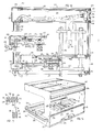
- FIGS. 12 to 14 relating to an automatic processing station constituting one of the modules of the machine.
- Said station comprises a window 231 defined by two crosspieces 232, 233 providing slides 234 facing each other for the introduction and reception of a pallet, the forward movement of the pallet being limited by two stop blocks 235 and 236.
- the end of a longitudinal rail 237 for the rotation of the pallets is fixed to the cross member 232 and there circulates the front edge 238 of the pallets 239.
- These are driven by a belt 241 to circular section which cooperates with the lower longitudinal striated strip 242 adjacent to the rear edge of the pallet.
- an L-shaped drawer 243 Opposite the window 231, and at a level below it, is arranged an L-shaped drawer 243, with two branches, namely a horizontal branch 244 and a vertical branch 245.
- the vertical branch 245 is fixed to the end 246 of the movable member 247 of a jack whose body 248 is fixed to the lower face 249 of a profile 251 in the general shape of an omega with a bottom 252 of large width ending in a posterior longitudinal edge 253 and an anterior longitudinal edge 254, both of which are U-shaped.
- a rail 255 supporting the belt 241 is at the front of the rear edge 253 and it is perforated to allow the passage of the horizontal branch 244 of the drawer 243.
- Said branch has at its front part a groove of rectangular section 256 suitable for receiving the rear studs 257 of the pallet-239. Near its attachment to the vertical branch 245, the horizontal branch 244 has a raceway 258.
- FIG. 13 shows a pallet which, under the driving effect of the belt 241, arrived opposite the window 231. In the last part of its course, it is supported by a die 261 having a raceway 262 which cooperates with the balls of the front studs of the pallet and which is carried by a vertical rod 263, which can be eclipsed.
- the jack 248 is actuated.
- the transverse edges of the pallet are introduced into the slides 234, the block 261 then being eclipsed.
- the end of insertion position is shown in FIG. 12, the front edge of the pallet then being in abutment against the blocks 235 and 236.
- the pallet, and the part which it carries are then in position so that the part is treated by a tool which has been shown schematically in 264.
- the path 256 of the drawer 243 extends the path formed by the front longitudinal rail 237 of the module so that an arriving pallet 265 can continue its path to the right of the window driven by the belt 241, the die 261 then being eclipsed.
- the automatic station comprises, as framework elements, in line with the crosspieces 232 and 233, two lower transverse beams 271. It is on these transverse beams that the columns 273 crossing the crosspieces 232 and 233 are assembled holes 274, 275, 276, 277 which these have.
- On the transverse beams 271 is fixed a beam with lower longitudinal grooves 278 and on the crosspieces 232 and 233, at the front end thereof, a beam with longitudinal grooves 279, thus at the height of the window 231 and prevailing over the whole module width.
- the beams 278 and 279 are used for fixing, at their ends, two cheeks 281 and 282 each consisting of a C-shaped sheet.
- each U has a notch for allow passage to the conveyor formed because the omega profile and the ends of which are fixed to the U-shaped irons 283.
- the securing of the conveyor 253 takes place by means of posts 293 fixed at their lower part on the transverse beams 271. To the fixing of the conveyor also contributes a longitudinal beam 294 bearing on a frame 295 crossed by the columns 273.
- a grooved beam has the section shown in FIG. 15. It has a generally rectangular outline and has grooves on one of its large longitudinal faces 301, three in number in the example shown 302, 303, 304 and on the face opposite, grooves of the same number but of greater depth 305, 306, 307.
- the association of two such grooved beams 308, 309 allows the mounting of plates 311 and their maintenance.
- the engaged plates may be sheets or else transparent plates such as "plexiglass". Between the beams with anterior grooves 279 and 286, two panes 311 and 312 were thus put in place. These panes can slide horizontally, which allows access to the part of the module observed and also to achieve continuity of separation between the inside the module and outside the module.
- a steel plate 314 which carries a battery of solenoid valves 315 with actuation buttons shown at 316. These buttons are accessible from the exterior but protected by strips 317 and 318 of plastics material removably mounted by clipping onto the beams with grooves 285 and 286 respectively. Said beams are also used for the removable mounting of a transparent plate 319.
- the grooved beam 285 and the posterior-superior grooved beam 292 are used, by their grooves 328, 329, for mounting two transparent plates 321 and 322 which constitute the ceiling 323 of a housing or casing 324 housing electro-pneumatic devices .
- Electrical or pneumatic conductors or conduits 325 protected in the housing 324 extend into sheaths 326 à.paroi 327 surrounding the posts 287.
Landscapes
- Engineering & Computer Science (AREA)
- Mechanical Engineering (AREA)
- Automatic Assembly (AREA)
- Electrical Discharge Machining, Electrochemical Machining, And Combined Machining (AREA)
- Press Drives And Press Lines (AREA)
- Escalators And Moving Walkways (AREA)
- Feeding Of Workpieces (AREA)
- Handling Of Sheets (AREA)
Priority Applications (1)
| Application Number | Priority Date | Filing Date | Title |
|---|---|---|---|
| AT83400419T ATE49366T1 (de) | 1982-03-05 | 1983-03-01 | Montage- oder bearbeitungsmaschinen fuer werkstuecke. |
Applications Claiming Priority (2)
| Application Number | Priority Date | Filing Date | Title |
|---|---|---|---|
| FR8203757A FR2522566B2 (fr) | 1982-03-05 | 1982-03-05 | Dispositif d'entrainement a courroie pour palettes d'une machine pour l'assemblage ou l'usinage de pieces |
| FR8203757 | 1982-03-05 |
Publications (3)
| Publication Number | Publication Date |
|---|---|
| EP0088680A2 true EP0088680A2 (de) | 1983-09-14 |
| EP0088680A3 EP0088680A3 (en) | 1985-04-17 |
| EP0088680B1 EP0088680B1 (de) | 1990-01-10 |
Family
ID=9271676
Family Applications (1)
| Application Number | Title | Priority Date | Filing Date |
|---|---|---|---|
| EP83400419A Expired - Lifetime EP0088680B1 (de) | 1982-03-05 | 1983-03-01 | Montage- oder Bearbeitungsmaschinen für Werkstücke |
Country Status (6)
| Country | Link |
|---|---|
| US (1) | US4513854A (de) |
| EP (1) | EP0088680B1 (de) |
| AT (1) | ATE49366T1 (de) |
| DE (1) | DE3381085D1 (de) |
| ES (1) | ES8404221A1 (de) |
| FR (1) | FR2522566B2 (de) |
Cited By (4)
| Publication number | Priority date | Publication date | Assignee | Title |
|---|---|---|---|---|
| FR2564075A1 (fr) * | 1984-05-16 | 1985-11-15 | Villejuif Etudes Indles | Installation de convoyage flexible et modulaire pour pieces de montage ou d'usinage |
| FR2589134A1 (fr) * | 1985-10-29 | 1987-04-30 | Prodel Jacques | Installation pour l'assemblage et/ou l'usinage de pieces portees par des palettes et palette faisant partie de cette installation |
| EP0223683A1 (de) * | 1985-10-29 | 1987-05-27 | Jacques Prodel | Vorrichtung zum Zusammenbau und/oder Gebrauch von Teilen, die von Paletten getragen werden sowie Palette für eine solche Vorrichtung |
| FR2611556A1 (fr) * | 1987-03-06 | 1988-09-09 | Telemecanique Electrique | Poste de travail entre une voie d'amenee de pieces et une voie d'evacuation perpendiculaire |
Families Citing this family (12)
| Publication number | Priority date | Publication date | Assignee | Title |
|---|---|---|---|---|
| FR2547520B1 (fr) * | 1983-06-17 | 1985-10-11 | Prodel Maurice | Installation modulaire pour l'assemblage et/ou l'usinage de pieces, avec dispositifs claviers-afficheurs a chaque poste |
| AT392050B (de) * | 1984-02-06 | 1991-01-10 | Sticht Walter | Fertigungsanlage mit mehreren einzelstationen |
| AT397779B (de) * | 1989-03-08 | 1994-06-27 | Sticht Fertigungstech Stiwa | Fertigungsanlage zum bearbeiten und montieren von bauteilen |
| JPH049854U (de) * | 1990-05-16 | 1992-01-28 | ||
| IL96799A (en) * | 1990-12-27 | 1995-11-27 | Fuselage Eng Services | Aircraft fuselage construction including food carrier |
| FR2679164B1 (fr) * | 1991-07-17 | 1993-10-15 | Telemecanique | Dispositif pour deplacer des pieces d'un poste a un autre le long d'une ligne de leur traitement. |
| DE4129294A1 (de) * | 1991-09-03 | 1993-03-04 | Protech Automation Gmbh | Duplex-foerderlinie |
| US5351801A (en) * | 1993-06-07 | 1994-10-04 | Board Of Regents - Univ. Of Nebraska | Automated laboratory conveyor system |
| US6533101B2 (en) | 1998-06-24 | 2003-03-18 | Asyst Technologies, Inc. | Integrated transport carrier and conveyor system |
| US6223886B1 (en) | 1998-06-24 | 2001-05-01 | Asyst Technologies, Inc. | Integrated roller transport pod and asynchronous conveyor |
| US6481558B1 (en) | 1998-12-18 | 2002-11-19 | Asyst Technologies, Inc. | Integrated load port-conveyor transfer system |
| US6308818B1 (en) | 1999-08-02 | 2001-10-30 | Asyst Technologies, Inc. | Transport system with integrated transport carrier and directors |
Family Cites Families (23)
| Publication number | Priority date | Publication date | Assignee | Title |
|---|---|---|---|---|
| GB416968A (en) * | 1933-03-20 | 1934-09-20 | Jacques Rome | Improvements in and relating to garages for automobiles and the like |
| US2652919A (en) * | 1949-11-07 | 1953-09-22 | Cutler Hammer Inc | Drive system for conveyers |
| US2837223A (en) * | 1953-11-03 | 1958-06-03 | Wolff Ivan | Automobile parking apparatus |
| US3315778A (en) * | 1956-10-17 | 1967-04-25 | Kenhos Dev Pool | Machine tools |
| US3221754A (en) * | 1962-12-05 | 1965-12-07 | Toledo Scale Corp | Dishwashing machines |
| US3313393A (en) * | 1963-06-17 | 1967-04-11 | Standard Tool & Mfg Company | Pallet transfer device |
| US3272240A (en) * | 1963-11-15 | 1966-09-13 | Roth Wilfred | Container filling transfer mechanism |
| US3530571A (en) * | 1967-12-15 | 1970-09-29 | Cincinnati Milacron Inc | Manufacturing system |
| FR2068731B1 (de) * | 1969-10-31 | 1974-08-09 | Villemaud Jean | |
| DE2103738A1 (de) * | 1971-01-27 | 1972-08-10 | Kleiber, Armin, 7500 Karlsruhe | Längs- und querverfahrbare Palette |
| US4014428A (en) * | 1973-05-04 | 1977-03-29 | Ossbahr C | Modular article conveyor |
| SE372917B (de) * | 1973-05-04 | 1975-01-20 | C G R Ossbahr | |
| DE2401503C3 (de) * | 1974-01-12 | 1978-12-21 | Cross Europa-Werk Gmbh, 7317 Wendlingen | Übergabeeinrichtung für Werkstückträger an den Übergabestationen einer Transferstraße |
| NL176841C (nl) * | 1975-03-04 | 1985-06-17 | Philips Nv | Transport inrichting voor testmonsterdragers, alsmede deze dragers. |
| IT1034819B (it) * | 1975-04-03 | 1979-10-10 | Situno Holding Sa | Gruppo ditrasporto ad incrocio particolarmente adatto per il trasporto o lo smistamento di giornali riviste e altri articoli a fogli sovrapposti |
| DE2518689C3 (de) * | 1975-04-26 | 1981-07-09 | Friedrich Wilhelm 8900 Augsburg Ortmann | Werkstücktransporteinrichtung für im Grundriß viereckige Transferstraßen |
| CH596062A5 (de) * | 1976-01-16 | 1978-02-28 | Lanco Ag | |
| DE2644136A1 (de) * | 1976-09-30 | 1978-04-06 | Bosch Gmbh Robert | Foerderbandsystem |
| DE2710180A1 (de) * | 1977-03-09 | 1978-09-14 | Will E C H Gmbh & Co | Foerdereinrichtung fuer zu stapeln aufeinandergeschichtete gegenstaende |
| DE2752268A1 (de) * | 1977-11-23 | 1979-06-07 | Hellmut Scheffler | Vorrichtung zum foerdern, bearbeiten und speichern von werkstuecken |
| FR2417238A7 (fr) * | 1978-02-14 | 1979-09-07 | Bibonne Christian | Dispositif transporteur d'objets miniaturises tels que des modeles reduits de voitures |
| CH636550A5 (fr) * | 1978-12-27 | 1983-06-15 | Maurice Prodel | Poste de travail d'une machine pour l'assemblage et/ou l'usinage de pieces. |
| EP0050080B1 (de) * | 1980-10-14 | 1985-03-20 | Maurice Prodel | Montage- und/oder Bearbeitungsanlage für Werkstücke, welche durch laufende und arrettierbare Werkstückträger getragen werden |
-
1982
- 1982-03-05 FR FR8203757A patent/FR2522566B2/fr not_active Expired
-
1983
- 1983-03-01 DE DE8383400419T patent/DE3381085D1/de not_active Expired - Lifetime
- 1983-03-01 AT AT83400419T patent/ATE49366T1/de not_active IP Right Cessation
- 1983-03-01 EP EP83400419A patent/EP0088680B1/de not_active Expired - Lifetime
- 1983-03-03 US US06/471,852 patent/US4513854A/en not_active Expired - Lifetime
- 1983-03-04 ES ES520343A patent/ES8404221A1/es not_active Expired
Cited By (6)
| Publication number | Priority date | Publication date | Assignee | Title |
|---|---|---|---|---|
| FR2564075A1 (fr) * | 1984-05-16 | 1985-11-15 | Villejuif Etudes Indles | Installation de convoyage flexible et modulaire pour pieces de montage ou d'usinage |
| FR2589134A1 (fr) * | 1985-10-29 | 1987-04-30 | Prodel Jacques | Installation pour l'assemblage et/ou l'usinage de pieces portees par des palettes et palette faisant partie de cette installation |
| EP0223683A1 (de) * | 1985-10-29 | 1987-05-27 | Jacques Prodel | Vorrichtung zum Zusammenbau und/oder Gebrauch von Teilen, die von Paletten getragen werden sowie Palette für eine solche Vorrichtung |
| FR2597450A2 (fr) * | 1985-10-29 | 1987-10-23 | Prodel Jacques | Installation pour l'assemblage et/ou l'usinage de pieces portees par des palettes et palette faisant partie de cette installation |
| US4832171A (en) * | 1985-10-29 | 1989-05-23 | Prodel Jacques M | Installation for assembling and/or machining parts carried on pallets, and a pallet forming a part of said installation |
| FR2611556A1 (fr) * | 1987-03-06 | 1988-09-09 | Telemecanique Electrique | Poste de travail entre une voie d'amenee de pieces et une voie d'evacuation perpendiculaire |
Also Published As
| Publication number | Publication date |
|---|---|
| EP0088680B1 (de) | 1990-01-10 |
| EP0088680A3 (en) | 1985-04-17 |
| ES520343A0 (es) | 1984-05-01 |
| ES8404221A1 (es) | 1984-05-01 |
| US4513854A (en) | 1985-04-30 |
| FR2522566A2 (fr) | 1983-09-09 |
| ATE49366T1 (de) | 1990-01-15 |
| DE3381085D1 (de) | 1990-02-15 |
| FR2522566B2 (fr) | 1986-06-13 |
Similar Documents
| Publication | Publication Date | Title |
|---|---|---|
| EP0088680B1 (de) | Montage- oder Bearbeitungsmaschinen für Werkstücke | |
| EP0050080B1 (de) | Montage- und/oder Bearbeitungsanlage für Werkstücke, welche durch laufende und arrettierbare Werkstückträger getragen werden | |
| EP2020388B2 (de) | Bewegliche Plattform zur Fehlerbehebung in einem automatisierten Lager | |
| FR2832654A1 (fr) | Dispositif pour le tri de colis par separation morphologique | |
| EP0026754A1 (de) | Lagereinrichtung zur automatischen Auswahl und Entnahme von Artikeln | |
| EP0527689B1 (de) | Lineare Fördervorrichtung mit freien Trägerplatten | |
| FR2535293A1 (fr) | Procede et installation pour le stockage d'objets a manutention automatisee | |
| FR2524089A1 (fr) | Roulement a glissement lineaire et table a coulissement lineaire equipee d'un tel roulement | |
| CA1284123C (fr) | Installation de transport a cables aeriens | |
| EP0738675B1 (de) | Lagerung mittels mobiler Wagen mit geneigtem Chassis | |
| FR2588284A1 (fr) | Machine a tricoter rectiligne avec un dispositif de chariot deplacable dans une position d'entretien | |
| FR2675791A1 (fr) | Transstockeur sous forme d'un portique roulant pour un magasin de materiau en barres. | |
| FR2731645A1 (fr) | Appareil pour couper un element plat flexible, notamment une bande transporteuse | |
| FR2690637A1 (fr) | Installation de manutention pour le transport de flans d'une machine de découpage à un dispositif d'empilage. | |
| EP0223683A1 (de) | Vorrichtung zum Zusammenbau und/oder Gebrauch von Teilen, die von Paletten getragen werden sowie Palette für eine solche Vorrichtung | |
| EP1270048A1 (de) | Regal mit Skis in geneigter Stellung | |
| FR2491897A1 (fr) | Module de mise en circulation de palettes porte-pieces pour atelier flexible d'usinage ou d'assemblage et atelier flexible comprenant de tels modules | |
| FR2541974A1 (fr) | Module de mise en circulation de palettes porte-pieces pour atelier flexible d'usinage ou d'assemblage et atelier flexible comprenant de tels modules | |
| FR2512723A1 (fr) | Installation pour l'assemblage et/ou l'usinage de pieces portees par des palettes circulantes et immobilisables | |
| FR2703284A1 (fr) | Portique mobile à rails enterrés. | |
| FR2624484A1 (fr) | Magasin a rouleaux pour rouleaux de supercalandres | |
| FR2545398A1 (fr) | Installation pour l'assemblage et/ou l'usinage de pieces portees par des palettes circulantes et immobilisables | |
| FR1278789A (fr) | Perfectionnements aux installations pour le garage automatique des véhicules et opérations analogues | |
| FR2510527A1 (fr) | Dispositif pour le stockage de pieces, notamment entre deux postes de travail | |
| FR2966137A1 (fr) | Ligne d'emboutissage de flans de tole |
Legal Events
| Date | Code | Title | Description |
|---|---|---|---|
| PUAI | Public reference made under article 153(3) epc to a published international application that has entered the european phase |
Free format text: ORIGINAL CODE: 0009012 |
|
| AK | Designated contracting states |
Designated state(s): AT BE CH DE GB IT LI LU NL SE |
|
| PUAL | Search report despatched |
Free format text: ORIGINAL CODE: 0009013 |
|
| AK | Designated contracting states |
Designated state(s): AT BE CH DE GB IT LI LU NL SE |
|
| 17P | Request for examination filed |
Effective date: 19851016 |
|
| 17Q | First examination report despatched |
Effective date: 19870206 |
|
| GRAA | (expected) grant |
Free format text: ORIGINAL CODE: 0009210 |
|
| RAP1 | Party data changed (applicant data changed or rights of an application transferred) |
Owner name: PRODEL, JACQUES |
|
| RIN1 | Information on inventor provided before grant (corrected) |
Inventor name: PRODEL, JACQUES Inventor name: PRODEL, MAURICE |
|
| AK | Designated contracting states |
Kind code of ref document: B1 Designated state(s): AT BE CH DE GB IT LI LU NL SE |
|
| REF | Corresponds to: |
Ref document number: 49366 Country of ref document: AT Date of ref document: 19900115 Kind code of ref document: T |
|
| REF | Corresponds to: |
Ref document number: 3381085 Country of ref document: DE Date of ref document: 19900215 |
|
| GBT | Gb: translation of ep patent filed (gb section 77(6)(a)/1977) | ||
| ITF | It: translation for a ep patent filed | ||
| PLBE | No opposition filed within time limit |
Free format text: ORIGINAL CODE: 0009261 |
|
| STAA | Information on the status of an ep patent application or granted ep patent |
Free format text: STATUS: NO OPPOSITION FILED WITHIN TIME LIMIT |
|
| 26N | No opposition filed | ||
| ITTA | It: last paid annual fee | ||
| EPTA | Lu: last paid annual fee | ||
| EAL | Se: european patent in force in sweden |
Ref document number: 83400419.4 |
|
| REG | Reference to a national code |
Ref country code: GB Ref legal event code: IF02 |
|
| PGFP | Annual fee paid to national office [announced via postgrant information from national office to epo] |
Ref country code: GB Payment date: 20020227 Year of fee payment: 20 |
|
| PGFP | Annual fee paid to national office [announced via postgrant information from national office to epo] |
Ref country code: CH Payment date: 20020325 Year of fee payment: 20 |
|
| PGFP | Annual fee paid to national office [announced via postgrant information from national office to epo] |
Ref country code: DE Payment date: 20020326 Year of fee payment: 20 Ref country code: BE Payment date: 20020326 Year of fee payment: 20 |
|
| PGFP | Annual fee paid to national office [announced via postgrant information from national office to epo] |
Ref country code: AT Payment date: 20020327 Year of fee payment: 20 |
|
| PGFP | Annual fee paid to national office [announced via postgrant information from national office to epo] |
Ref country code: SE Payment date: 20020328 Year of fee payment: 20 |
|
| PGFP | Annual fee paid to national office [announced via postgrant information from national office to epo] |
Ref country code: NL Payment date: 20020329 Year of fee payment: 20 |
|
| PGFP | Annual fee paid to national office [announced via postgrant information from national office to epo] |
Ref country code: LU Payment date: 20020410 Year of fee payment: 20 |
|
| PG25 | Lapsed in a contracting state [announced via postgrant information from national office to epo] |
Ref country code: LI Free format text: LAPSE BECAUSE OF EXPIRATION OF PROTECTION Effective date: 20030228 Ref country code: GB Free format text: LAPSE BECAUSE OF EXPIRATION OF PROTECTION Effective date: 20030228 Ref country code: CH Free format text: LAPSE BECAUSE OF EXPIRATION OF PROTECTION Effective date: 20030228 |
|
| PG25 | Lapsed in a contracting state [announced via postgrant information from national office to epo] |
Ref country code: NL Free format text: LAPSE BECAUSE OF EXPIRATION OF PROTECTION Effective date: 20030301 Ref country code: LU Free format text: LAPSE BECAUSE OF EXPIRATION OF PROTECTION Effective date: 20030301 Ref country code: AT Free format text: LAPSE BECAUSE OF EXPIRATION OF PROTECTION Effective date: 20030301 |
|
| REG | Reference to a national code |
Ref country code: GB Ref legal event code: PE20 Effective date: 20030228 |
|
| REG | Reference to a national code |
Ref country code: CH Ref legal event code: PL |
|
| BE20 | Be: patent expired |
Owner name: *PRODEL JACQUES Effective date: 20030301 |
|
| NLV7 | Nl: ceased due to reaching the maximum lifetime of a patent | ||
| EUG | Se: european patent has lapsed |