EP0087647B1 - Kombinations-Eindeckrahmen für nebeneinander einzubauende Dachfenster - Google Patents
Kombinations-Eindeckrahmen für nebeneinander einzubauende Dachfenster Download PDFInfo
- Publication number
- EP0087647B1 EP0087647B1 EP83101312A EP83101312A EP0087647B1 EP 0087647 B1 EP0087647 B1 EP 0087647B1 EP 83101312 A EP83101312 A EP 83101312A EP 83101312 A EP83101312 A EP 83101312A EP 0087647 B1 EP0087647 B1 EP 0087647B1
- Authority
- EP
- European Patent Office
- Prior art keywords
- coupling
- webs
- cover
- installed position
- corner
- Prior art date
- Legal status (The legal status is an assumption and is not a legal conclusion. Google has not performed a legal analysis and makes no representation as to the accuracy of the status listed.)
- Expired
Links
- 238000009434 installation Methods 0.000 claims abstract description 12
- 230000008878 coupling Effects 0.000 claims description 46
- 238000010168 coupling process Methods 0.000 claims description 46
- 238000005859 coupling reaction Methods 0.000 claims description 46
- 238000003780 insertion Methods 0.000 claims description 8
- 230000037431 insertion Effects 0.000 claims description 8
- 230000000875 corresponding effect Effects 0.000 claims 6
- 230000002596 correlated effect Effects 0.000 claims 1
- 230000003014 reinforcing effect Effects 0.000 claims 1
- 230000000284 resting effect Effects 0.000 claims 1
- 238000010276 construction Methods 0.000 description 2
- 238000004519 manufacturing process Methods 0.000 description 2
- 229910052782 aluminium Inorganic materials 0.000 description 1
- XAGFODPZIPBFFR-UHFFFAOYSA-N aluminium Chemical compound [Al] XAGFODPZIPBFFR-UHFFFAOYSA-N 0.000 description 1
- 239000011324 bead Substances 0.000 description 1
- 230000006835 compression Effects 0.000 description 1
- 238000007906 compression Methods 0.000 description 1
- 238000011161 development Methods 0.000 description 1
- 230000018109 developmental process Effects 0.000 description 1
- 229910052751 metal Inorganic materials 0.000 description 1
- 239000002184 metal Substances 0.000 description 1
- 230000007704 transition Effects 0.000 description 1
- XLYOFNOQVPJJNP-UHFFFAOYSA-N water Substances O XLYOFNOQVPJJNP-UHFFFAOYSA-N 0.000 description 1
Images


Classifications
-
- E—FIXED CONSTRUCTIONS
- E04—BUILDING
- E04D—ROOF COVERINGS; SKY-LIGHTS; GUTTERS; ROOF-WORKING TOOLS
- E04D13/00—Special arrangements or devices in connection with roof coverings; Protection against birds; Roof drainage ; Sky-lights
- E04D13/14—Junctions of roof sheathings to chimneys or other parts extending above the roof
- E04D13/147—Junctions of roof sheathings to chimneys or other parts extending above the roof specially adapted for inclined roofs
- E04D13/1473—Junctions of roof sheathings to chimneys or other parts extending above the roof specially adapted for inclined roofs specially adapted to the cross-section of the parts extending above the roof
- E04D13/1475—Junctions of roof sheathings to chimneys or other parts extending above the roof specially adapted for inclined roofs specially adapted to the cross-section of the parts extending above the roof wherein the parts extending above the roof have a generally rectangular cross-section
-
- E—FIXED CONSTRUCTIONS
- E04—BUILDING
- E04D—ROOF COVERINGS; SKY-LIGHTS; GUTTERS; ROOF-WORKING TOOLS
- E04D3/00—Roof covering by making use of flat or curved slabs or stiff sheets
- E04D3/36—Connecting; Fastening
- E04D3/366—Connecting; Fastening by closing the space between the slabs or sheets by gutters, bulges, or bridging elements, e.g. strips
Definitions
- the invention relates to a combination cover frame, the type defined in the preamble of claim 1 and an associated coupling rail.
- Combination roofing frames of this type were developed by the applicant in order to avoid too large gaps when installing several roof windows to be installed next to one another and / or one above the other without impairing the weatherproof connection to the roof covering.
- combination roofing frames have proven their worth, the different distances and cross-sectional dimensions of the rafters make it necessary to adjust the distance between adjacent roof windows.
- the object of the invention is now to improve a combination cover frame and corresponding coupling rails of the type defined in the preamble of claim 1 in such a way that one and the same cover frame upper parts and / or lower parts can be connected in different lateral installation distances in each case against lateral shear and rainproof.
- the combination cover frame of the type defined in the preamble of claim 1 is characterized according to the invention by the features of the characterizing part of claim 1.
- the same cover frame upper parts and / or lower parts can be used for all installation distances, only the simple and inexpensive to produce coupling rails and channel parts having to be manufactured in different widths. As a result, the production is significantly cheaper and also with respect to the storage of the much more complex upper and lower parts, significant cost savings are achieved. All parts of the cover frame can be made in a conventional manner from aluminum sheet, other metal sheet or from a suitable plastic.
- the combination roofing frame shown for two adjacent roof windows consists of two upper parts 2, two lower parts 6, two side parts 10, a channel part 13 and a coupling rail 20 with an associated insertion rail 23.
- the upper parts 2 each have a raised cover web 3 for covering the corner of the upper frame piece of a frame 1, furthermore in the installed position on the ridge side and under the roof covering, and a connecting flange 5 which is bent outwards at one side edge.
- the lower parts 6 each have an upstanding cover web 7 for covering the frame lower part of an associated frame 1 and a connection flange 8 in the installed position on the eaves side of the roof covering with a lead apron 8B arranged thereon, the mutually facing edge regions of the connecting flanges of the lower parts 6 to be installed next to one another Embodiment shown are designed so that they can be joined together overlapping at different installation distances.
- the side parts 10 each have an upstanding cover web 11 for the associated side piece of the frame 1 and in the installed position under the lateral roof covering, the connecting flange 12, which has a transition section 12A at the eaves-side end, which in the installed position is led out to the top of the roof covering, which is facilitated by an accordion-like folded area of the associated cover web 11.
- the channel part 13 has one the width of the floor wall 15, which is matched to the installation spacing, and covering webs 14, which stand up on the side edges, for the side pieces of the two associated frame 1.
- the parts mentioned in this paragraph are of conventional construction.
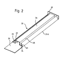
- the coupling rail corresponds to the two-part construction shown in FIG. 2, in which an insertion rail 23 is arranged on the inside of the top wall 22, the lateral guide webs 24 of which engage in the brackets 21 formed between the top wall 22 and the bracket webs 21 bent back at the side edges.
- the insertion rail 23 has a channel-shaped central part connecting the guide webs 24, the bottom of which forms a support wall 26 in the position of installation in the plane between the corner edges 5A of the coupling webs 5 to be connected.
- the respective supporting webs 25 connecting the supporting wall 26 with a guide web 24 serve to support the corner edges 5A of the connecting flanges 4 against a pushing force acting in the direction of a compression of the two upper parts 2.
- the support wall 26 should expediently be offset slightly to the roof relative to the plane of the corner edges 5A, in deviation from the schematic representation shown in FIG. 3 3, so that the support webs 25 form a reliable abutment for the corner edges 5A.
- the coupling rail 20 is formed in one piece and, instead of the insertion rail 23, is provided with two beads 30, which are recessed in a groove-like manner in the cover wall 22 and form the support webs 25 for the corner edges 5A of the coupling webs 5.
- the coupling rail 20 is once again formed in one piece, a channel-like depression being arranged in place of the insertion rail 23 of the top wall 22, the side walls of which form the support webs 25 and the bottom wall of the support wall 26.
- the coupling rail 20 shown in FIG. 2 has at its eaves-side end a right-angled inward end web 27 which, in the installed position, covers the interior of the coupling rail against the ingress of water driven upwards by wind.
- a mounting tab 28 At the ridge-side end of the coupling rail 20 there is a mounting tab 28 which continues the top wall 22 and which is installed in the. Condition around the upper edges of the connecting flanges 4 of the associated upper parts 2 is bent inwards.
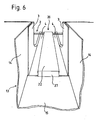
- This installation position of the coupling rail 20 is shown in perspective in FIG. 6 from a viewing angle directed upwards from the channel part 14 '.
- the coupling rail shown in FIGS. 2 to 5 can also serve to connect corresponding coupling rails, not shown, on the mutually facing side edges of the connecting flanges 8 of the lower parts 6.
- the lead aprons 8B of the lower parts 6 can overlap one another.
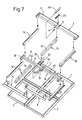
- an intermediate part 16 is arranged between two superimposed frame 1, which has a bottom wall 17, an upper cover web 3A for covering the lower frame piece of the frame 1 above it, a lower cover web 7A for covering the upper frame piece of the frame 1 below, has an outside connection flange 18 and an inside connection flange 18A, which is provided with a coupling web 19 bent back obliquely outwards.
- bracket tab 28 of the coupling rail 20 protruding on the ridge side is bent inwards around not shown, flanged edges on the upper edge of the inside connecting flanges 18A of the two intermediate parts 16.
Landscapes
- Engineering & Computer Science (AREA)
- Architecture (AREA)
- Civil Engineering (AREA)
- Structural Engineering (AREA)
- Mechanical Engineering (AREA)
- Roof Covering Using Slabs Or Stiff Sheets (AREA)
- Window Of Vehicle (AREA)
Description
- Die Erfindung betrifft einen Kombinations-Eindeckrahmen, der im Oberbegriff des Patentanspruches 1 definierten Art sowie eine zugehörige Kopplungsschiene.
- Kombinations-Eindeckrahmen dieser Art wurden von der Anmelderin entwickelt, um beim Einbau mehrerer in geringen Abständen nebeneinander und/oder übereinander einzubauender Dachfenster zu große Zwischenräume zu vermeiden, ohne den wetterdichten Anschluß an die Dacheindeckung zu beeinträchtigen. Obgleich sich derartige Kombinations-Eindeckrahmen durchaus bewöhrt haben, ist es wegen der unterschiedlichen Abstände und Querschnittsabmessungen der Dachsparren vielfach erforderlich, den Abstand zwischen benachbarten Dachfenstern diesen anzupassen. Hierzu mußten bisher nicht nur Rinnenteile unterschiedlicher Breite, sondern auch eine Vielzahl von verschiedenen Eindeckrahmen-Oberteilen mit jeweils auf den Einbauabstand abgestimmter Länge des seitlichen Überstandes des Anschlußflansches hergestellt und vorrätig gehalten werden, was die Fertigungskosten erhöht und die Lagerhaltung kompliziert.
- Aufgabe der Erfindung ist es nun, einen Kombinations-Eindeckrahmen und entsprechende Kopplungsschienen der im Oberbegriff des Patentanspruches 1 definierten Art so zu verbessern, daß ein und dieselben Eindeckrahmen-Oberteile und/oder Unterteile in verschiedenen seitlichen Einbauabständen jeweils seitenschubfest und regendicht verbindbar sind.
- Zur Lösung dieser Aufgabe ist der Kombinations-Eindeckrahmen der im Oberbegriff des Patentanspruches 1 definierten Art erfindungsgemäß gekennzeichnet durch die Merkmale des kennzeichnenden Teiles des Patentanspruches 1.
- Durch die erfindungsgemäße Ausbildung der Kopplungsschiene können für alle Einbauabstände die gleichen Eindeckrahmen-Oberteile und/oder Unterteile verwendet werden, wobei lediglich die einfachen und unaufwendig herzustellenden Kopplungsschienen und Rinnenteile in verschiedenen Breiten gefertigt zu werden brauchen. Hierdurch wird die Fertigung wesentlich verbilligt und auch hinsichtlich der Lagerhaltung der wesentlich aufwendigeren Ober- und Unterteile eine bedeutende Kostenersparnis erzielt. Alle Teile der Eindeckrahmen können in herkömmlicher Weise aus Aluminiumblech, sonstigem Metallblech oder aus einem geeigneten Kunststoff gefertigt werden.
- Vorteilhafte weitere Ausgestaltungen des Eindeckrahmens sind in den Unteransprüchen 2 bis 5 beschrieben.
- Im folgenden werden bevorzugte Ausführungsformen des erfindungsgemäßen Kombinations-Eindeckrahmens unter Bezugnahme auf die beigefügten Zeichnungen weiter erläutert. Es zeigen :
- Figur 1 eine die Einbaufolge erläuternde schematische Darstellung der Einzelteile eines erfindungsgemäßen Kombinations-Eindeckrahmens für zwei nebeneinanderliegende Dachfenster,
- Figur 2 eine perspektivische Ansicht einer bevorzugten Ausführungsform der Kopplungsschiene,
- Figur 3 einen schematischen Querschnitt durch die Kopplungsschiene gemäß Fig. im eingebauten Zustand,
- Figur4 einen schematischen Querschnitt durch eine abgewandelte Kopplungsschiene im eingebauten Zustand,
- Figur 5 einen schematischen Querschnitt durch eine weitere abgewandelte Ausführungsform der Kopplungsschiene im eingebauten Zustand,
- Figur 6 eine perspektivische Teilansicht der Oberteile eines Kombinations-Eindeckrahmens mit eingebauter Kopplungsschiene und
- Figur 7 eine die Einbaufolge erläuternde schematische perspektivische Ansicht der Einzelteile eines erfindungsgemäßen Kombinations-Eindeckrahmens für zwei nebeneinanderliegende und zwei darüberliegende Dachfenster.
- Wie Fig. 1 zeigt, besteht der dargestellte Kombinations-Eindeckrahmen für zwei nebeneinanderliegende Dachfenster aus zwei Oberteilen 2, zwei Unterteilen 6, zwei Seitenteilen 10, einem Rinnenteil 13 sowie einer Kopplungsschiene 20 mit zugehöriger Einlegeschiene 23.
- Die Oberteile 2 weisen jeweils einen hochstehenden Abdecksteg 3 zur eckumgreifenden Abdeckung des oberen Rahmenstücks eines Blendrahmens 1, ferner einen in der Einbaustellung firstseitig und seitlich unter die Dacheindeckung reichenden Anschlußflansch 4 und einen an dessen einem Seitenrand auswärts schräg zurückgebogenen Kopplungssteg 5 auf. Die Unterteile 6 besitzen jeweils einen hochstehenden Abdecksteg 7 zur eckumgreifenden Abdeckung des Rahmenunterstücks eines zugeordneten Blendrahmens 1 und einen in der Einbaustellung traufseitig auf der Dacheindeckung aufliegenden Anschlußflansch 8 mit daran angeordneter Bleischürze 8B, wobei die einander zugewandten Randbereiche der Anschlußflansche der nebeneinander einzubauenden Unterteile 6 bei der dargestellten Ausführungsform so ausgebildet sind, daß sie sich bei verschiedenen Einbauabständen jeweils überlappend zusammenfügen lassen. Die Seitenteile 10 besitzen jeweils einen hochstehenden Abdecksteg 11 für das zugehörige Seitenstück des Blendrahmens 1 sowie einen in der Einbaustellung unter die seitliche Dacheindeckung reichenden Anschlußflansch 12, der am traufseitigen Ende einen Übergangsabschnitt 12A aufweist, der in der Einbaustellung zur Oberseite der Dacheindeckung herausgeführt wird, was durch einen zieharmonikaähnlich gefalteten Bereich des zugehörigen Abdecksteges 11 erleichert wird. Das Rinnenteil 13 besitzt eine in ihrer Breite auf den Einbauabstand abgestimmten Bodenwand 15 und an deren Seitenrändern hochstehende Abdeckstege 14 für die Seitenstücke der beiden zugeordneten Blendrahmen 1. Die in diesem Absatz genannten Teile sind herkömmlicher Konstruktion.
- Die Kopplungsschiene entspricht der in Fig. 2 dargestellten, zweiteiligen Konstruktion, bei der an der Innenseite der Deckwand 22 eine Einlegeschiene 23 angeordnet ist, deren seitliche Führungsstege 24 in die zwischen der Deckwand 22 und deren an den Seitenrändern schräg zurückgebogenen Halterungsstegen 21 gebildeten Winkel eingreift. Die Einlegeschiene 23 besitzt einen die Führungsstege 24 verbindenden, rinnenförmigen Mittelteil, dessen Boden eine in. der Einbaustellung in der Ebene zwischen den Eckkanten 5A der der zu verbindenden Kopplungsstege 5 liegende Stützwand 26 bildet. Die jeweils die Stützwand 26 mit einem Führungssteg 24 verbindenden Stützstege 25 dienen zum Abstützen der Eckkanten 5A der Anschlußflansche 4 gegen eine in Richtung eines Zusammendrängens der beiden Oberteile 2 wirkende Schubkraft. Zur sicheren Abstützung soll die-Stützwand 26 zweckmäßig abweichend von der in Fig.3 3 wiedergegebenen schematischen Darstellung relativ zur Ebene der Eckkanten 5A geringfügig dacheinwärts versetzt sein, damit die Stützstege 25 ein zuverlässiges Widerlager für die Eckkanten 5A bilden.
- Bei der in Fig. dargestellten, abgewandelten Ausführungsform ist die Kopplungsschiene 20 einstückig ausgebildet und an Stelle der Einlegeschiene 23 mit zwei der Deckwand 22 rinnenartig eingetieften Sicken 30 versehen, welche die Stützstege 25 für die Eckkanten 5A der Kopplungsstege 5 bilden.
- Bei der in Fig. 5 dargestellten Ausführungsform ist die Kopplungsschiene 20 wiederum einstückig ausgebildet, wobei an Stelle der Einlegeschiene 23 der Deckwand 22 eine rinnenartige Eintiefung angeordnet ist, deren Seitenwände die Stützstege 25 und deren Bodenwand die Stützwand 26 bilden.
- Die in Fig. 2 dargestellten Kopplungsschiene 20 besitzt an ihrem traufseitigen Ende einen rechtwinklig einwärts abgebogenen Abschlußsteg 27, der in der Einbaustellung den Innenraum der Kopplungsschiene gegen das Eindringen von durch Wind aufwärts getriebenen Wasser abdeckt. Am firstseitigen Ende der Kopplungsschiene 20 ist eine die Deckwand 22 fortsetzende Halterungslasche 28 angeordnet, die im eingebauten. Zustand um die Oberkanten der Anschlußflansche 4 der zugehörigen Oberteile 2 einwärts herumgebogen wird. Diese Einbaustellung der Kopplungsschiene 20 ist in Fig. 6 von einem aus dem Rinnenteil 14 'dachaufwärts gerichteten Blickwinkel perspektivisch dargestellt.
- Die in den Fig. 2 bis 5 dargestellte Kopplungsschiene kann gleichermaßen auch zur Verbindung von entsprechenden, nicht dargestellten Kopplungsschienen an den einander zugewandten Seitenrändern der Anschlußflansche 8 der Unterteile 6 dienen. Auch in diesem Fall können die Bleischürzen 8B der Unterteile 6 einander überlappen.
- Bei der in Fig. 7 schematische dargestellten Ausführungsform eines Kombinations-Eindeckrahmens für zwei nebeneinander liegende und zwei darüberliegende Dachfenster entsprechen die Oberteile 2, die Unterteile 6, die Seitenteile 10 und die Rinnenteile 13 der bereits vorstehend gegebenen Erläuterung. Zwischen zwei übereinanderliegenden Blendrahmen 1 ist bei dieser Ausführungsform jeweils ein Zwischenteil 16 angeordnet, das eine Bodenwand 17, einen oberen Abdecksteg 3A zur eckumgreifenden Abdeckung des unteren Rahmenstücks des darüberliegenden Blendrahmens 1, einen unteren Abdecksteg 7A zum eckumgreifenden Abdecken des oberen Rahmenstücks des darunterliegenden Blendrahmens 1, einen außenseitigen Anschlu- βflansch 18 und einen innenseitigen Anschlußflansch 18A aufweist, der mit einem schräg auswärts zurückgebogenen Kopplungssteg 19 versehen ist. Zum seitenschubfesten, regendichten Verbinden der beiden Zwischenteile 16 wird wiederum eine Kopplungsschiene 20 der in Fig. 2 dargestellten Art mit einer in diese eingeschobenen Einlegeschiene 23 verwendet. Die firstseitig überstehende Halterungslasche 28 der Kopplungsschiene 20 wird dabei um nicht dargestellte, hochgebördelte Ränder am Oberrand der innenseitigen Anschlußflansche 18A der beiden Zwischenteile 16 einwärts herumgebogen.
- Der vorstehend anhand bevorzugter Ausführungsformen erläuterte Kombinations-Eindeckrahmen und die zugehörige Kopplungsschiene können vom Fachmann je nach den Anforderungen in verschiedener Weise zweckentsprechend abgewandelt werden, sofern dabei die seitenschubfeste Abstützung der Eckkanten 5A der Kopplungsstege 5 bzw. 19 erhalten bleibt.
Claims (6)
Priority Applications (1)
| Application Number | Priority Date | Filing Date | Title |
|---|---|---|---|
| AT83101312T ATE12960T1 (de) | 1982-02-26 | 1983-02-11 | Kombinations-eindeckrahmen fuer nebeneinander einzubauende dachfenster. |
Applications Claiming Priority (2)
| Application Number | Priority Date | Filing Date | Title |
|---|---|---|---|
| DE3206871 | 1982-02-26 | ||
| DE3206871A DE3206871C1 (de) | 1982-02-26 | 1982-02-26 | Kombinations-Eindeckrahmen fuer nebeneinander einzubauende Dachfenster |
Publications (2)
| Publication Number | Publication Date |
|---|---|
| EP0087647A1 EP0087647A1 (de) | 1983-09-07 |
| EP0087647B1 true EP0087647B1 (de) | 1985-04-24 |
Family
ID=6156721
Family Applications (1)
| Application Number | Title | Priority Date | Filing Date |
|---|---|---|---|
| EP83101312A Expired EP0087647B1 (de) | 1982-02-26 | 1983-02-11 | Kombinations-Eindeckrahmen für nebeneinander einzubauende Dachfenster |
Country Status (5)
| Country | Link |
|---|---|
| US (2) | US4543753A (de) |
| EP (1) | EP0087647B1 (de) |
| AT (1) | ATE12960T1 (de) |
| DE (1) | DE3206871C1 (de) |
| DK (1) | DK154099C (de) |
Cited By (3)
| Publication number | Priority date | Publication date | Assignee | Title |
|---|---|---|---|---|
| USD750804S1 (en) | 2013-08-30 | 2016-03-01 | Vkr Holding A/S | Connector element for use in a flashing assembly for roof windows |
| EP4442923A1 (de) * | 2023-04-05 | 2024-10-09 | VKR Holding A/S | Seitliches zwischenblech für längsblech, bausatz mit solchen blechen und verfahren zum verblechen von zwei dachteilen |
| EP4722465A2 (de) | 2024-10-04 | 2026-04-08 | VKR Holding A/S | Kit aus abdeckelementen, verfahren zur herstellung eines abdeckungselementkits und verwendung des kits aus abdeckelementen |
Families Citing this family (47)
| Publication number | Priority date | Publication date | Assignee | Title |
|---|---|---|---|---|
| DE3206871C1 (de) * | 1982-02-26 | 1983-06-01 | Velux GmbH - Bauzubehör, 2000 Hamburg | Kombinations-Eindeckrahmen fuer nebeneinander einzubauende Dachfenster |
| US4703596A (en) * | 1986-09-16 | 1987-11-03 | Plasteco, Inc. | Grid skylight system |
| FR2654133A1 (fr) * | 1989-11-03 | 1991-05-10 | Safiza | Ensemble d'eclairage et/ou de ventilation d'un local couvert comportant une fenetre de toit associee a une fenetre de cloison. |
| CA2120118C (en) * | 1994-03-28 | 2001-12-11 | John Frederick Ward | Exterior building product device |
| DK172054B1 (da) * | 1995-10-04 | 1997-09-29 | Rasmussen Kann Ind As | Inddækningsrammestykke af metalplade til inddækning af karmkonstruktioner for ovenlysvinduer eller lignende taggennembrydende bygningsstrukturer samt inddækningsramme omfattende et sådant stykke |
| DE19600509C1 (de) * | 1996-01-09 | 1997-04-03 | Harald Barocke | Dachfenstereinbau für mindestens zwei nebeneinander einzubauende Dachfenster |
| US6195948B1 (en) | 1999-07-23 | 2001-03-06 | Poly Lite Windows Ltd. | Skylights to accommodate on site adjustments for variations in installations |
| WO2003074812A1 (en) | 2002-03-07 | 2003-09-12 | Vkr Holding A/S | Sheet flashing member and flashing kit comprising such sheet flashing members |
| AU2003275944A1 (en) * | 2002-12-16 | 2004-07-09 | Vkr Holding A/S | Side flashing member and a method of making it |
| CN100473793C (zh) * | 2002-12-16 | 2009-04-01 | Vkr控股公司 | 侧防水构件及其制造方法 |
| EP1576244B1 (de) * | 2002-12-16 | 2021-06-02 | VKR Holding A/S | Blech-abweiserinne für dachfenster und verfahren zum anbringen einer derartigen blech-abweiserinne an einer ein dach durchdringenden baustruktur |
| US20080184637A1 (en) * | 2007-02-06 | 2008-08-07 | Architectural Composite Technologies, Llc | Trim assembly |
| EP2331763A1 (de) | 2008-10-02 | 2011-06-15 | Jerome O. Blomberg | Randloses mehrfach-deckenleuchtensystem und rauchablasssystem dafür |
| US8438799B2 (en) | 2008-10-02 | 2013-05-14 | T&M Inventions, Llc | Support structures on roofs |
| US8438798B2 (en) * | 2008-10-02 | 2013-05-14 | T&M Inventions, Llc | Roof penetrating closure structures and systems |
| FR2960627B1 (fr) * | 2010-05-28 | 2012-09-14 | Solairedirect | Structure photovoltaique etanche et aeree |
| PL2472029T3 (pl) | 2010-12-29 | 2020-04-30 | Vkr Holding A/S | Sposób montowania obróbki blacharskiej do okna dachowego oraz system obróbki blacharskiej do okna dachowego |
| EP2472028B1 (de) | 2010-12-29 | 2017-12-13 | VKR Holding A/S | Verfahren zur Installation einer Fensteranordnung mit einer Reihe von benachbarten Fenstern und eine derartige Fensteranordnung |
| EP2653631B1 (de) | 2010-12-29 | 2017-06-28 | VKR Holding A/S | Fenstersystem mit einer Rahmenstruktur und Klammeranordnung |
| PL226250B1 (pl) | 2011-01-31 | 2017-06-30 | Fakro Pp Spółka Z Ograniczoną Odpowiedzialnością | Zestaw do obrobki blacharskiej, uszczelniajacy polaczenie zespolu co najmniej dwoch konstrukcji przenikajacych przez dach |
| US8438800B2 (en) * | 2011-03-14 | 2013-05-14 | T&M Inventions, Llc | Support structures on roofs |
| US8438801B2 (en) * | 2011-03-14 | 2013-05-14 | T&M Inventions, Llc | Support structures on roofs |
| US9127461B2 (en) | 2011-04-14 | 2015-09-08 | T&M Inventions, Llc | Thermal barrier about roof support structure |
| US9637927B2 (en) | 2011-04-14 | 2017-05-02 | T&M Inventions, Llc | Diverter |
| US9677279B2 (en) | 2011-04-14 | 2017-06-13 | T&M Inventions, Llc | Condensation control in a roof mounted load support structure |
| US9745790B2 (en) | 2012-08-10 | 2017-08-29 | Norwood Architecture, Inc. | Prefabricated flashing product |
| US8959842B2 (en) | 2012-08-10 | 2015-02-24 | Norwood Architecture, Inc. | Prefabricated flashing product |
| US9745789B2 (en) | 2012-08-10 | 2017-08-29 | Norwood Architecture, Inc. | Prefabricated flashing product |
| USD714969S1 (en) | 2012-08-10 | 2014-10-07 | Norwood Architecture, Inc. | Window flashing product |
| DK178016B1 (en) * | 2013-01-25 | 2015-03-16 | Vkr Holding As | A flashing kit and a method for flashing roof penetrating structures arranged in an inclined roof with one structure above another |
| US9534390B2 (en) | 2013-03-15 | 2017-01-03 | T&M Inventions, Llc | Support structures on roofs |
| US9032671B1 (en) | 2014-01-17 | 2015-05-19 | T&M Inventions, Llc | Support structure using extended-length diverter |
| US10161179B2 (en) | 2015-11-13 | 2018-12-25 | Norwood Architecture, Inc. | Three-dimensional prefabricated flashing scaffolding system |
| DE102015222840A1 (de) * | 2015-11-19 | 2017-05-24 | Robert Bosch Gmbh | Solarkollektor-Dachintegrationseinrichtung sowie Verfahren zum Montieren eines Solarkollektors |
| US10352048B2 (en) | 2016-10-13 | 2019-07-16 | T&M Inventions, Llc | Load support structure for use on roof |
| DK180351B1 (en) | 2019-01-10 | 2021-01-22 | Vkr Holding As | An end closure for a cladding for a roof window and a roof window arrangement |
| DK180344B1 (en) * | 2019-01-10 | 2021-01-15 | Vkr Holding As | A middle flashing assembly and a method for weather-proofing a roof window arrangement |
| US11255090B2 (en) | 2019-01-10 | 2022-02-22 | Vkr Holding A/S | Connector bracket for interconnecting roof windows, a roof window arrangement, and a method for mounting at least two windows in an inclined roof structure |
| US11002016B2 (en) | 2019-01-10 | 2021-05-11 | Vkr Holding A/S | Connector element for a flashing assembly for use in a roof window arrangement, and a method for weather proofing a roof window arrangement |
| US11473307B2 (en) * | 2019-09-05 | 2022-10-18 | Greg Smyth | Skylight and smoke vent gutter uplift channel assembly |
| DK181500B1 (en) * | 2020-12-30 | 2024-03-12 | Vkr Holding As | A roof window system with a cover assembly |
| DK181645B1 (en) * | 2023-02-17 | 2024-08-23 | Vkr Holding As | A packed flashing assembly for use with a group of roof windows and a method for weatherproofing a group of roof windows |
| DK181959B8 (en) * | 2023-02-17 | 2025-04-30 | Vkr Holding As | A weatherproofing assembly for use with a group of roof windows comprising at least three roof windows |
| DK202370170A1 (en) * | 2023-04-05 | 2024-10-24 | Vkr Holding As | A flashing assembly comprising a top flashing arrangement, a roof element system comprising such a flashing assembly, and a method of manufacturing a flashing assembly |
| CN222575969U (zh) * | 2023-04-05 | 2025-03-07 | Vkr控股公司 | 用于在两个屋顶窗户之间使用的防水组件以及一组屋顶窗户 |
| EP4571008B1 (de) | 2023-12-11 | 2026-05-20 | Vkr Holding As | Verfahren zur anpassung eines abdeckelements zur abdeckung eines spalts zwischen dachstrukturen |
| DK182324B1 (en) * | 2024-10-04 | 2026-04-17 | Vkr Holding As | A flashing assembly for use between two roof windows mounted in an inclined roof structure, a group of roof windows mounted with such a flashing assembly, and a method for mounting a flashing assembly between two roof windows |
Family Cites Families (16)
| Publication number | Priority date | Publication date | Assignee | Title |
|---|---|---|---|---|
| US1090186A (en) * | 1913-07-23 | 1914-03-17 | Christian Yauch | Skylight. |
| US1840041A (en) * | 1930-03-06 | 1932-01-05 | James Ackroyd And Sons | Skylight |
| US1971160A (en) * | 1932-06-20 | 1934-08-21 | Julius J Ohlis | Skylight construction |
| US2014925A (en) * | 1934-09-14 | 1935-09-17 | Frank C Bradley | Skylight |
| US2777548A (en) * | 1956-06-11 | 1957-01-15 | Letha F Adams | Window frame assembly |
| DE1856279U (de) * | 1961-11-24 | 1962-08-09 | Handel & Mack O H G | Blech-eindeckrahmen fuer dach-wohnraumfenster. |
| US3805471A (en) * | 1970-11-19 | 1974-04-23 | Perfect Module Sys Inc | Building panel construction system |
| DE2142733C3 (de) * | 1971-08-26 | 1980-04-03 | Hoesch Werke Ag, 4600 Dortmund | Eindeckrahmen für in der Dachfläche liegende Dachfenster |
| US3835614A (en) * | 1971-09-16 | 1974-09-17 | Donn Prod Inc | Suspension system |
| DE2503519A1 (de) * | 1975-01-29 | 1976-08-05 | Beijer Gmbh | Eindeckrahmen zur dichtenden verbindung der dachhaut mit einem dachwohnraumfenster |
| US4123883A (en) * | 1977-02-28 | 1978-11-07 | Sunworks, Inc. | Solar energy collector |
| JPS54109222A (en) * | 1978-02-15 | 1979-08-27 | Matsushita Electric Works Ltd | Skylight with dew drainage |
| US4194325A (en) * | 1978-10-12 | 1980-03-25 | Butler Manufacturing Company | Gutter system for skylights or the like |
| DE8000998U1 (de) * | 1980-01-16 | 1980-04-17 | Steeb, Christian, 7247 Sulz | Eindeckrahmen fuer dachfenster |
| US4471584A (en) * | 1982-02-24 | 1984-09-18 | Ibg International, Inc. | Unitized skylight structure |
| DE3206871C1 (de) * | 1982-02-26 | 1983-06-01 | Velux GmbH - Bauzubehör, 2000 Hamburg | Kombinations-Eindeckrahmen fuer nebeneinander einzubauende Dachfenster |
-
1982
- 1982-02-26 DE DE3206871A patent/DE3206871C1/de not_active Expired
-
1983
- 1983-02-11 AT AT83101312T patent/ATE12960T1/de not_active IP Right Cessation
- 1983-02-11 EP EP83101312A patent/EP0087647B1/de not_active Expired
- 1983-02-22 US US06/468,304 patent/US4543753A/en not_active Expired - Fee Related
- 1983-02-24 DK DK087083A patent/DK154099C/da active
-
1985
- 1985-05-30 US US06/739,550 patent/US4621466A/en not_active Expired - Lifetime
Cited By (3)
| Publication number | Priority date | Publication date | Assignee | Title |
|---|---|---|---|---|
| USD750804S1 (en) | 2013-08-30 | 2016-03-01 | Vkr Holding A/S | Connector element for use in a flashing assembly for roof windows |
| EP4442923A1 (de) * | 2023-04-05 | 2024-10-09 | VKR Holding A/S | Seitliches zwischenblech für längsblech, bausatz mit solchen blechen und verfahren zum verblechen von zwei dachteilen |
| EP4722465A2 (de) | 2024-10-04 | 2026-04-08 | VKR Holding A/S | Kit aus abdeckelementen, verfahren zur herstellung eines abdeckungselementkits und verwendung des kits aus abdeckelementen |
Also Published As
| Publication number | Publication date |
|---|---|
| US4543753A (en) | 1985-10-01 |
| DK154099B (da) | 1988-10-10 |
| DK87083D0 (da) | 1983-02-24 |
| US4621466A (en) | 1986-11-11 |
| DE3206871C1 (de) | 1983-06-01 |
| EP0087647A1 (de) | 1983-09-07 |
| DK154099C (da) | 1989-02-27 |
| ATE12960T1 (de) | 1985-05-15 |
| DK87083A (da) | 1983-08-27 |
Similar Documents
| Publication | Publication Date | Title |
|---|---|---|
| DE3206871C1 (de) | Kombinations-Eindeckrahmen fuer nebeneinander einzubauende Dachfenster | |
| DE69314357T2 (de) | Dichtungsanordnung für fenster, besonders dachfenster | |
| DE69901823T2 (de) | Dichtungselement und rahmen für ein das dach durchdringendes bauelement | |
| DE69513162T2 (de) | Anschlussstreifen für dachelemente | |
| EP0148429B1 (de) | Eindeckrahmen | |
| EP0215231A2 (de) | Auf einem Aufsetzkranz oder dergleichen angeordnetes, gewölbtes Dachoberlicht | |
| EP4007096B1 (de) | An einer begrenzungsfläche eines gebäudes festlegbares kabelrinnensystem | |
| DE2929215A1 (de) | Rahmen fuer einen solarkollektor | |
| DE19613043A1 (de) | Pfosten-Sprossen-Konstruktion | |
| DE3513404A1 (de) | Distanz- und belueftungselement fuer zweischalige dachkonstruktionen | |
| DE4135891C2 (de) | Verbindung von Dachelementen | |
| DE19855028A1 (de) | Dachfensterkonstruktion | |
| DE2349710A1 (de) | Waermegedaemmte dacheindeckung | |
| DE2263565A1 (de) | Abdichtungsprofil fuer bauwerke | |
| CH601605A5 (en) | Roof edge joint construction | |
| DE4131460C2 (de) | Randeinfassung für ein Flachdach oder einen Balkon | |
| EP0271049A1 (de) | Dämmplatte aus Hartschaum-Kunststoff | |
| DE4446412A1 (de) | Oberlichtelement | |
| EP0450265B1 (de) | Kantenbekleidung für dünne Fensterbänke | |
| DE69008660T2 (de) | Verfahren zur Verbindung von zwei Platten oder Folien unter einer Ecke, Verbindungselement zu seiner Anwendung und Dacheindeckung mit solchem Verfahren hergestellt. | |
| DE4422471A1 (de) | Randprofil für einen Dachabschluß eines Gebäudes | |
| AT262564B (de) | Außenmauerverkleidung für Gebäude | |
| EP0325204B1 (de) | Torblattglied | |
| AT378219B (de) | Dacheindeckung | |
| DE2759760C2 (de) | Lüftungsvorrichtung für mit Dacheindeckungsplatten eingedeckte Dächer |
Legal Events
| Date | Code | Title | Description |
|---|---|---|---|
| PUAI | Public reference made under article 153(3) epc to a published international application that has entered the european phase |
Free format text: ORIGINAL CODE: 0009012 |
|
| AK | Designated contracting states |
Designated state(s): AT BE CH FR GB LI LU NL SE |
|
| 17P | Request for examination filed |
Effective date: 19830723 |
|
| GRAA | (expected) grant |
Free format text: ORIGINAL CODE: 0009210 |
|
| AK | Designated contracting states |
Designated state(s): AT BE CH FR GB LI LU NL SE |
|
| REF | Corresponds to: |
Ref document number: 12960 Country of ref document: AT Date of ref document: 19850515 Kind code of ref document: T |
|
| ET | Fr: translation filed | ||
| PLBE | No opposition filed within time limit |
Free format text: ORIGINAL CODE: 0009261 |
|
| STAA | Information on the status of an ep patent application or granted ep patent |
Free format text: STATUS: NO OPPOSITION FILED WITHIN TIME LIMIT |
|
| 26N | No opposition filed | ||
| EPTA | Lu: last paid annual fee | ||
| EAL | Se: european patent in force in sweden |
Ref document number: 83101312.3 |
|
| PGFP | Annual fee paid to national office [announced via postgrant information from national office to epo] |
Ref country code: NL Payment date: 20010220 Year of fee payment: 19 |
|
| PGFP | Annual fee paid to national office [announced via postgrant information from national office to epo] |
Ref country code: SE Payment date: 20010221 Year of fee payment: 19 |
|
| PGFP | Annual fee paid to national office [announced via postgrant information from national office to epo] |
Ref country code: LU Payment date: 20010223 Year of fee payment: 19 |
|
| REG | Reference to a national code |
Ref country code: GB Ref legal event code: IF02 |
|
| PGFP | Annual fee paid to national office [announced via postgrant information from national office to epo] |
Ref country code: GB Payment date: 20020122 Year of fee payment: 20 |
|
| PG25 | Lapsed in a contracting state [announced via postgrant information from national office to epo] |
Ref country code: LU Free format text: LAPSE BECAUSE OF NON-PAYMENT OF DUE FEES Effective date: 20020211 |
|
| PG25 | Lapsed in a contracting state [announced via postgrant information from national office to epo] |
Ref country code: SE Free format text: LAPSE BECAUSE OF NON-PAYMENT OF DUE FEES Effective date: 20020212 |
|
| PGFP | Annual fee paid to national office [announced via postgrant information from national office to epo] |
Ref country code: AT Payment date: 20020220 Year of fee payment: 20 |
|
| PGFP | Annual fee paid to national office [announced via postgrant information from national office to epo] |
Ref country code: FR Payment date: 20020221 Year of fee payment: 20 Ref country code: BE Payment date: 20020221 Year of fee payment: 20 |
|
| PGFP | Annual fee paid to national office [announced via postgrant information from national office to epo] |
Ref country code: CH Payment date: 20020424 Year of fee payment: 20 |
|
| PG25 | Lapsed in a contracting state [announced via postgrant information from national office to epo] |
Ref country code: NL Free format text: LAPSE BECAUSE OF NON-PAYMENT OF DUE FEES Effective date: 20020901 |
|
| EUG | Se: european patent has lapsed |
Ref document number: 83101312.3 |
|
| NLV4 | Nl: lapsed or anulled due to non-payment of the annual fee |
Effective date: 20020901 |
|
| PG25 | Lapsed in a contracting state [announced via postgrant information from national office to epo] |
Ref country code: LI Free format text: LAPSE BECAUSE OF EXPIRATION OF PROTECTION Effective date: 20030210 Ref country code: GB Free format text: LAPSE BECAUSE OF EXPIRATION OF PROTECTION Effective date: 20030210 Ref country code: CH Free format text: LAPSE BECAUSE OF EXPIRATION OF PROTECTION Effective date: 20030210 |
|
| PG25 | Lapsed in a contracting state [announced via postgrant information from national office to epo] |
Ref country code: AT Free format text: LAPSE BECAUSE OF EXPIRATION OF PROTECTION Effective date: 20030211 |
|
| BE20 | Be: patent expired |
Owner name: V. *KANN RASMUSSEN HOLDING A/S Effective date: 20030211 |
|
| REG | Reference to a national code |
Ref country code: GB Ref legal event code: PE20 Effective date: 20030210 |
|
| REG | Reference to a national code |
Ref country code: CH Ref legal event code: PL |