EP0085788B1 - Schaltungsanordnung zur Dekodierung von SECAM-Farbfernsehsignalen - Google Patents
Schaltungsanordnung zur Dekodierung von SECAM-Farbfernsehsignalen Download PDFInfo
- Publication number
- EP0085788B1 EP0085788B1 EP19820112022 EP82112022A EP0085788B1 EP 0085788 B1 EP0085788 B1 EP 0085788B1 EP 19820112022 EP19820112022 EP 19820112022 EP 82112022 A EP82112022 A EP 82112022A EP 0085788 B1 EP0085788 B1 EP 0085788B1
- Authority
- EP
- European Patent Office
- Prior art keywords
- signals
- phase
- colour
- switching
- stage
- Prior art date
- Legal status (The legal status is an assumption and is not a legal conclusion. Google has not performed a legal analysis and makes no representation as to the accuracy of the status listed.)
- Expired
Links
- 230000010363 phase shift Effects 0.000 claims 1
- 230000008878 coupling Effects 0.000 description 2
- 238000010168 coupling process Methods 0.000 description 2
- 238000005859 coupling reaction Methods 0.000 description 2
- 230000005540 biological transmission Effects 0.000 description 1
- 238000010586 diagram Methods 0.000 description 1
- 230000000694 effects Effects 0.000 description 1
- 230000002452 interceptive effect Effects 0.000 description 1
- 238000000034 method Methods 0.000 description 1
Images


Classifications
-
- H—ELECTRICITY
- H04—ELECTRIC COMMUNICATION TECHNIQUE
- H04N—PICTORIAL COMMUNICATION, e.g. TELEVISION
- H04N11/00—Colour television systems
- H04N11/06—Transmission systems characterised by the manner in which the individual colour picture signal components are combined
- H04N11/18—Transmission systems characterised by the manner in which the individual colour picture signal components are combined using simultaneous and sequential signals, e.g. SECAM-system
- H04N11/186—Decoding means therefor
Definitions
- the invention is based on a circuit arrangement for decoding color television signals according to the SECAM system, in which the two color signals for red and blue are alternately transmitted from line to line on a subcarrier in frequency modulation and the individual color signals to avoid interference with the color signals the luminance signal is switched according to a certain scheme on the transmitter side in the phase in which a logic circuit is provided which, with the aid of a switching stage, cancels the phase changes made by the transmitter.
- the color signals are transmitted sequentially from line to line, alternating blue and red in frequency modulation on one subcarrier each.
- the two signals for red and blue are switched from line to line in phase according to the following scheme:
- Phase switching from line to line can occur.
- the result is an interfering difference signal of 156.250 KHZ formed from the two carrier frequencies 4406.250 KHZ for red and 4250.000 KHZ for blue.
- the crosstalk is caused by the coupling of the input signal to the output signal of the delay line, by the double reflection of the input and output signals in the delay line, as a result of which the signals pass through them 3 times (3T), by the switchover and by coupling the two discriminators for demodulation of the two color signals.
- a circuit arrangement is known (DE-AS 2 911 190) which serves to determine the phase of the receiver to switch the incoming color signals in such a way that the different phase position caused by the transmission system during one line is switched over to the phase position of the other two lines in such a way that all lines have the same phase position.
- this phase equality relates only to the lines of a field.
- the phase position of one line is switched over to that of the other two lines, so that again all lines of this field have the same phase position.
- This is opposite to the previous field.
- the phase of the lines changes from field to field. If, for example, the lines of the odd-numbered fields have phase 0, the lines of the even-numbered fields have phase n.
- the phases of the signals only remain constant and the same for the duration of one field, while they remain the same in the following
- the field is also constant and the same, but is out of phase with the lines of the previous field.
- the known circuit arrangement it is in particular the same polarity of color signals that are to be recorded on a magnetic tape in spaces without inclined tracks.
- the object of the invention is to switch the phase of the signals from field to field in a circuit arrangement of the type described in the introduction in such a way that the switching of the individual color signals made by the transmitter for all lines in all fields is reversed and made the same. This object is achieved by the measures specified in the patent claims.
- the invention is based on the knowledge that the phase change made by the transmitter must be reversed, so that the chrominance signals always have the same phase position (0.0), so that the disruptive differential frequency of 156.250 kHz is always the same from line to line
- the phase position has (10 times the line frequency) which is less disturbing, since this fixed phase relationship of the (BY) and (RY) signals on the screen in the line direction only cause saturation errors. However, nothing changes from line to line, avoiding the annoying horizontal stripes on the screen.
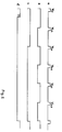
- FIG. 1 is a block diagram and in
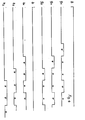
- FIG. 2 - Figure 4 are the signals present at the marked points of Figure 1 are reproduced.
- the received color signal F is switched to the input 1 of an amplifier stage 2.
- Stage 2 has two outputs 3 and 4, at which the same but opposite phase signals F and F are applied, which are fed to inputs 5, 6 of a switching stage 7.
- the output 8 of the switching stage 7 is connected to the input 9 of the SECAM decoder 10, from whose outputs 11, 12 the decoded color signals (R-Y), (B-Y) are taken.
- the output 8 of the switching stage 7 is switched to that output 3 or 4 of the stage 2 at which e.g. the 0 phase of the color signal F is.
- Switching stage 7 is brought into the required switching position by switching logic 14-20. This will be explained below with the aid of the signal curves recorded in FIGS. 2, 3 and 4 at the marked points a-h in the circuit according to FIG. 1.
- the image-frequency pulses V are applied to the clock input CI of a D flip-flop 14 (FIG. 2a). At the D input there are line-frequency pulses H (FIG. 3e). The vertical frequency is divided by 2 by the flip-flop 14 (FIG. 2b). A subsequent stage 15 divides this frequency by 3 ( Figure 2c).
- This signal c is connected to the input 16 of a monostable multivibrator 17, the time constant T of which can be influenced by a voltage of an up-down counter 18.
- the output voltage according to FIG. 2d is switched to the reset input of a divider 19, to which line-frequency pulses (FIG. 3e) are fed.
- Level 19 acts as a divider with a factor of 1: 3. Three different time constants are shown in FIG.
- FIGS. 3f1, f2 and f3 results at the output f of the stage 19.
- a signal curve according to FIGS. 4g1, g2, g3 is produced at the output of these gates for the odd-numbered fields V1.1, V2.1, V3.1, if there is an H potential at point b, or a signal curve h1, h2 or h3 for the even-numbered partial images V1.2, V2.2, V3.2, if there is an O potential at point b.
- These voltages according to FIGS. 4g and 4h serve as switching voltage for switching stage 7, which switches the changeover switch to the position that the same phase always appears at its output.
- the color signal at the input and output of the delay line is compared in a phase comparison stage 21 in the SECAM decoder.
- H potential for example, reaches the enable input En of the stage 18, which changes the voltage step by step with the aid of the c signal until the monostable multivibrator 17 has the suitable time constant T has, so that the switch 7 switches the signal voltage such that always the same at the input and output of the delay line Phase.
- the changeover switch 7 is brought into the required switching sequence 0, 0 ⁇ or ⁇ , ⁇ , 0 (FIG. 4g, FIG. 4h).
Landscapes
- Engineering & Computer Science (AREA)
- Multimedia (AREA)
- Signal Processing (AREA)
- Processing Of Color Television Signals (AREA)
- Color Television Systems (AREA)
Applications Claiming Priority (2)
| Application Number | Priority Date | Filing Date | Title |
|---|---|---|---|
| DE19823203040 DE3203040C2 (de) | 1982-01-30 | 1982-01-30 | Schaltungsanordnung zur Dekodierung von SECAM-Farbfernsehsignalen |
| DE3203040 | 1982-01-30 |
Publications (3)
| Publication Number | Publication Date |
|---|---|
| EP0085788A2 EP0085788A2 (de) | 1983-08-17 |
| EP0085788A3 EP0085788A3 (en) | 1985-05-22 |
| EP0085788B1 true EP0085788B1 (de) | 1988-04-20 |
Family
ID=6154318
Family Applications (1)
| Application Number | Title | Priority Date | Filing Date |
|---|---|---|---|
| EP19820112022 Expired EP0085788B1 (de) | 1982-01-30 | 1982-12-27 | Schaltungsanordnung zur Dekodierung von SECAM-Farbfernsehsignalen |
Country Status (3)
| Country | Link |
|---|---|
| EP (1) | EP0085788B1 (enExample) |
| DE (1) | DE3203040C2 (enExample) |
| GR (1) | GR77391B (enExample) |
Families Citing this family (2)
| Publication number | Priority date | Publication date | Assignee | Title |
|---|---|---|---|---|
| FR2565055B1 (fr) * | 1984-05-22 | 1988-01-29 | Labo Electronique Physique | Chaine de diffusion de signaux de television en couleurs de type secam |
| JP3723764B2 (ja) | 2001-11-27 | 2005-12-07 | 住友ゴム工業株式会社 | 空気入りタイヤ |
Family Cites Families (3)
| Publication number | Priority date | Publication date | Assignee | Title |
|---|---|---|---|---|
| NO135557C (enExample) * | 1970-08-27 | 1977-04-20 | Ted Bildplatten | |
| US4220964A (en) * | 1977-11-21 | 1980-09-02 | Sony Corporation | Secam recording and reproducing system |
| DE2911190C2 (de) * | 1979-03-22 | 1981-02-05 | Grundig E.M.V. Elektro-Mechanische Versuchsanstalt Max Grundig, 8510 Fuerth | Schaltungsanordnung zur Gleichpolung der Phase von SECAM-Farbfernsehsignalen |
-
1982
- 1982-01-30 DE DE19823203040 patent/DE3203040C2/de not_active Expired
- 1982-12-27 EP EP19820112022 patent/EP0085788B1/de not_active Expired
-
1983
- 1983-01-28 GR GR70354A patent/GR77391B/el unknown
Also Published As
| Publication number | Publication date |
|---|---|
| DE3203040A1 (de) | 1983-08-11 |
| EP0085788A3 (en) | 1985-05-22 |
| GR77391B (enExample) | 1984-09-11 |
| EP0085788A2 (de) | 1983-08-17 |
| DE3203040C2 (de) | 1984-01-05 |
Similar Documents
| Publication | Publication Date | Title |
|---|---|---|
| DE3048139A1 (de) | "normenwandler fuer ein quadratur-amplitudenmoduliertes signal" | |
| DE2461704A1 (de) | Geraet zur aufzeichnung und wiedergabe von pal-fernsehsignalen | |
| DE2558971B2 (de) | Verfahren und Schaltungsanordnung zur Aufbereitung von PAL-Farbartsignalen für die digitale Übertragung bzw. Verarbeitung | |
| DE2506850A1 (de) | Magnetisches aufzeichnungs- und/oder wiedergabesystem | |
| DE2906690C3 (de) | Signalgeneratorschaltung zum Erzeugen eines PAL- und bzw. oder SECAM-Bezugsfarbträgersignals | |
| EP0085788B1 (de) | Schaltungsanordnung zur Dekodierung von SECAM-Farbfernsehsignalen | |
| DE2221888A1 (de) | Farbfernsehempfaenger fuer Pal- und Secam-Norm | |
| DE2918982C2 (de) | Wiedergabegerät für ein auf einem Aufzeichnungsträger aufgezeichnetes Farbfernsehsignal | |
| DE2615451C2 (de) | Übertragungssystem für Farbfernsehsignale | |
| DE3930806C2 (enExample) | ||
| DE2856634A1 (de) | Schaltungsanordnung zur aufzeichnung und bzw. oder wiedergabe von pal-farbfernsehsignalen | |
| DE3825936C2 (de) | Einrichtung und Verfahren zur Codierung eines komponentenunterteilten digitalen Videosignals | |
| DE1762217C3 (de) | Schaltungsanordnung zur Transcodierung von Farbfernsehsignalen mit zeilensequentiell und simultan übertragenen Farbsignalen | |
| DE2533445C2 (de) | Farbfernsehübertragungssystem | |
| DE1935213C3 (de) | Schaltung zur Aufzeichnung und Wiedergabe eines Farbfemsehsignals | |
| AT346940B (de) | Schaltungsanordnung fuer das umkodieren von farbfernsehchrominanzsignalen | |
| DE2856663C2 (enExample) | ||
| DE2549744A1 (de) | Schaltungsanordnung zum demodulieren eines chrominanzsignals | |
| DE3941576C1 (enExample) | ||
| DE2546378A1 (de) | System und schaltungsanordnungen zur uebertragung, insbesondere zur aufzeichnung/wiedergabe von farbvideosignalen | |
| DE2241485C3 (de) | Steuerschaltung für einen PAL-Farbfernsehdecoder | |
| DE2138825C3 (de) | Schaltungsanordnung zur Dekodierung eines PAL-Farbbildsignals | |
| DE2259928A1 (de) | Dekodiersystem fuer farbfernsehempfaenger | |
| DE2652905A1 (de) | Verfahren zur transcodierung von farbfernsehsignalen | |
| DE2139113A1 (de) | Dekodiersystem für einen Farbfernsehempfänger |
Legal Events
| Date | Code | Title | Description |
|---|---|---|---|
| PUAI | Public reference made under article 153(3) epc to a published international application that has entered the european phase |
Free format text: ORIGINAL CODE: 0009012 |
|
| AK | Designated contracting states |
Designated state(s): BE CH FR IT LI LU NL |
|
| PUAL | Search report despatched |
Free format text: ORIGINAL CODE: 0009013 |
|
| AK | Designated contracting states |
Designated state(s): BE CH FR IT LI LU NL |
|
| 17P | Request for examination filed |
Effective date: 19850919 |
|
| 17Q | First examination report despatched |
Effective date: 19860919 |
|
| ITF | It: translation for a ep patent filed | ||
| GRAA | (expected) grant |
Free format text: ORIGINAL CODE: 0009210 |
|
| AK | Designated contracting states |
Kind code of ref document: B1 Designated state(s): BE CH FR IT LI LU NL |
|
| ET | Fr: translation filed | ||
| PLBE | No opposition filed within time limit |
Free format text: ORIGINAL CODE: 0009261 |
|
| STAA | Information on the status of an ep patent application or granted ep patent |
Free format text: STATUS: NO OPPOSITION FILED WITHIN TIME LIMIT |
|
| 26N | No opposition filed | ||
| ITTA | It: last paid annual fee | ||
| PGFP | Annual fee paid to national office [announced via postgrant information from national office to epo] |
Ref country code: BE Payment date: 19911217 Year of fee payment: 10 |
|
| PGFP | Annual fee paid to national office [announced via postgrant information from national office to epo] |
Ref country code: FR Payment date: 19911223 Year of fee payment: 10 |
|
| PGFP | Annual fee paid to national office [announced via postgrant information from national office to epo] |
Ref country code: CH Payment date: 19911230 Year of fee payment: 10 |
|
| PGFP | Annual fee paid to national office [announced via postgrant information from national office to epo] |
Ref country code: NL Payment date: 19911231 Year of fee payment: 10 |
|
| PGFP | Annual fee paid to national office [announced via postgrant information from national office to epo] |
Ref country code: LU Payment date: 19921119 Year of fee payment: 11 |
|
| PG25 | Lapsed in a contracting state [announced via postgrant information from national office to epo] |
Ref country code: LI Effective date: 19921231 Ref country code: BE Effective date: 19921231 Ref country code: CH Effective date: 19921231 |
|
| EPTA | Lu: last paid annual fee | ||
| BERE | Be: lapsed |
Owner name: DEUTSCHE THOMSON-BRANDT G.M.B.H. Effective date: 19921231 |
|
| PG25 | Lapsed in a contracting state [announced via postgrant information from national office to epo] |
Ref country code: NL Effective date: 19930701 |
|
| NLV4 | Nl: lapsed or anulled due to non-payment of the annual fee | ||
| PG25 | Lapsed in a contracting state [announced via postgrant information from national office to epo] |
Ref country code: FR Effective date: 19930831 |
|
| REG | Reference to a national code |
Ref country code: CH Ref legal event code: PL |
|
| REG | Reference to a national code |
Ref country code: FR Ref legal event code: ST |
|
| PG25 | Lapsed in a contracting state [announced via postgrant information from national office to epo] |
Ref country code: LU Free format text: LAPSE BECAUSE OF NON-PAYMENT OF DUE FEES Effective date: 19931227 |