EP0085457B1 - Sheet conveying device - Google Patents
Sheet conveying device Download PDFInfo
- Publication number
- EP0085457B1 EP0085457B1 EP83200104A EP83200104A EP0085457B1 EP 0085457 B1 EP0085457 B1 EP 0085457B1 EP 83200104 A EP83200104 A EP 83200104A EP 83200104 A EP83200104 A EP 83200104A EP 0085457 B1 EP0085457 B1 EP 0085457B1
- Authority
- EP
- European Patent Office
- Prior art keywords
- finger
- sheet
- shaft
- conveying path
- revolution
- Prior art date
- Legal status (The legal status is an assumption and is not a legal conclusion. Google has not performed a legal analysis and makes no representation as to the accuracy of the status listed.)
- Expired
Links
- 230000001154 acute effect Effects 0.000 claims description 2
- 238000005452 bending Methods 0.000 description 5
- 238000006073 displacement reaction Methods 0.000 description 5
- 238000007373 indentation Methods 0.000 description 3
- 238000006243 chemical reaction Methods 0.000 description 2
- 230000007423 decrease Effects 0.000 description 2
- 238000010276 construction Methods 0.000 description 1
- 230000001419 dependent effect Effects 0.000 description 1
- 238000012986 modification Methods 0.000 description 1
- 230000004048 modification Effects 0.000 description 1
- 230000000414 obstructive effect Effects 0.000 description 1
Images

Classifications
-
- B—PERFORMING OPERATIONS; TRANSPORTING
- B65—CONVEYING; PACKING; STORING; HANDLING THIN OR FILAMENTARY MATERIAL
- B65H—HANDLING THIN OR FILAMENTARY MATERIAL, e.g. SHEETS, WEBS, CABLES
- B65H9/00—Registering, e.g. orientating, articles; Devices therefor
- B65H9/16—Inclined tape, roller, or like article-forwarding side registers
- B65H9/166—Roller
-
- B—PERFORMING OPERATIONS; TRANSPORTING
- B65—CONVEYING; PACKING; STORING; HANDLING THIN OR FILAMENTARY MATERIAL
- B65H—HANDLING THIN OR FILAMENTARY MATERIAL, e.g. SHEETS, WEBS, CABLES
- B65H2404/00—Parts for transporting or guiding the handled material
- B65H2404/10—Rollers
- B65H2404/11—Details of cross-section or profile
- B65H2404/111—Details of cross-section or profile shape
- B65H2404/1114—Paddle wheel
-
- B—PERFORMING OPERATIONS; TRANSPORTING
- B65—CONVEYING; PACKING; STORING; HANDLING THIN OR FILAMENTARY MATERIAL
- B65H—HANDLING THIN OR FILAMENTARY MATERIAL, e.g. SHEETS, WEBS, CABLES
- B65H2404/00—Parts for transporting or guiding the handled material
- B65H2404/10—Rollers
- B65H2404/13—Details of longitudinal profile
- B65H2404/131—Details of longitudinal profile shape
- B65H2404/1315—Details of longitudinal profile shape conical
Definitions
- This invention relates to a sheet conveying device comprising a conveying path for sheets, an abutment strip along the conveying path, and means for advancing a sheet over the conveying path while an edge of the sheet is brought into and/or held in contact with the abutment strip, said means comprising a friction member secured to a rotatable shaft extending transversely across the conveying path, said friction member being provided with at least one flexible finger which is connected to the shaft, which extends in a direction which has an axial component in the direction to the abutment strip, and which, when the shaft rotates, traverses a surface of revolution which intersects the conveying path for the sheets.
- US Patent 3 671 719 describes a device of this kind in which a rotating conveyor means is used, which is provided with radially and axially extending resilient fingers.
- This conveyor means is disposed at a distance from the conveying path such that whenever a finger comes into contact with a sheet present in the conveying path said finger undergoes flexural deformation as a result of which its free end undergoes a displacement extending axially and towards the abutment strip.
- Devices of this kind can be used, inter alia, in office equipment in which sheets of copy material, documents to be copied, punched cards and the like are conveyed from a delivery station to a processing station. Contact with the abutment strip ensures that the sheets always reach the processing station in the same position.
- Another disadvantage of this known device is that a finger which as a result of deformation first experiences a displacement in the direction of the abutment strip will, upon further rotation of the conveyor means, experience one and the same displacement but then in the opposite direction.
- the conveyed sheet will be subjected to a torque which tends to move the leading part of the sheet away from the abutment strip.
- this known device cannot always achieve good positioning of a sheet against the abutment strip.
- the object of this invention is to provide a sheet conveying device which does not have the above disadvantages, and in a device as meant in the preamble, this is achieved in that the direction in. which each finger extends is the resultant of said axial component in the direction of the abutment strip and a tangential component in the direction of rotation of the shaft, that the said surface of revolution is the surface of a cone or a cylinder of revolution and that the said direction of the finger intersects a straight generatrix of said cone of cylinder of revolution at an acute angle.
- the friction member is so constructed that the surface of revolution traversed by the finger (or fingers) is the surface of a cone of revolution. Thereby it is achieved that the shaft of the friction member can be disposed parallel to the conveying path.
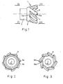
- Figs. 1, 2 and 3 show an embodiment of the friction member of the sheet conveying device according to the invention.
- the friction member 2 consists of a hollow part 2 having a surface in the form of a truncated circular cone, the vertical angle of which is 30°, and of a cylindrical hub 3 connected coaxially to that side of the hollow conical part 2 which has the smallest diameter. From the side having the largest diameter eight straight indentations 4 are formed in the conical part 2 at regular intervals. The direction of these indentations forms an angle of 45° with a straight directrix of the cone passing through the said indentation.
- fingers 5 form in the conical part 2, which fingers have a rectangular cross-section, and which, with respect to the axis of rotation, have a radial, an axial, and a tangential direction component.
- the length of the fingers is such that the free end 5a of a finger and the base 5b of an adjacent finger are situated on the same straight directrix of the cone.
- a hole 6 is formed in the cylindrical hub 3, through which hole a shaft 7 shown in Figs. 4 and 5 can be passed, which shaft can be driven by motor 8 to rotate the friction member.
- the friction member is made from a resiliently deformable material, e.g. rubber.
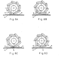
- the friction member is so disposed that the shaft 7 is parallel to a conveying path 11 for sheets 9 and includes a right angle with an abutment strip 10 for the sheets, said abutment strip 10 extending along the conveying path 11.
- the friction member is disposed at such a distance with regard to a plate 11 forming the conveying path 11 that the fingers can come into contact with a sheet 9 being present on said plate.
- Plate 11 is formed with an aperture 12 through which the fingers can pass without coming into contact with the plate if no sheet is being conveyed.
- the friction member can be so disposed that the shaft includes an angle with the conveying path.
- the angle included by a finger and the centre-line of the shaft may be 0, in other words the outer surface of the friction member may then be cylindrical.
- the fingers may be rigid and be secured to a tubular member so as to be freely pivotable, in such a way that a finger - at least when it comes into contact with a sheet - is held by springs or by stops on the tubular member in a position in which the finger has a radial, an axial, and a tangential direction component with respect to the axis of rotation. If a rigid finger is not returned to this position by springs after a frictional movement has been performed in the conveying plane, the tubular member must be provided with a (radially directed) stop which lifts the finger from the sheet directly after the finger has passed a radial line direction downwards.
Landscapes
- Engineering & Computer Science (AREA)
- Mechanical Engineering (AREA)
- Discharge By Other Means (AREA)
- Feeding Of Articles By Means Other Than Belts Or Rollers (AREA)
- Delivering By Means Of Belts And Rollers (AREA)
- Registering Or Overturning Sheets (AREA)
Applications Claiming Priority (2)
| Application Number | Priority Date | Filing Date | Title |
|---|---|---|---|
| NL8200355 | 1982-02-01 | ||
| NL8200355A NL8200355A (nl) | 1982-02-01 | 1982-02-01 | Vellentransportinrichting. |
Publications (2)
| Publication Number | Publication Date |
|---|---|
| EP0085457A1 EP0085457A1 (en) | 1983-08-10 |
| EP0085457B1 true EP0085457B1 (en) | 1986-04-23 |
Family
ID=19839166
Family Applications (1)
| Application Number | Title | Priority Date | Filing Date |
|---|---|---|---|
| EP83200104A Expired EP0085457B1 (en) | 1982-02-01 | 1983-01-24 | Sheet conveying device |
Country Status (5)
| Country | Link |
|---|---|
| US (1) | US4546964A (enExample) |
| EP (1) | EP0085457B1 (enExample) |
| JP (1) | JPS58135046A (enExample) |
| DE (1) | DE3363117D1 (enExample) |
| NL (1) | NL8200355A (enExample) |
Families Citing this family (22)
| Publication number | Priority date | Publication date | Assignee | Title |
|---|---|---|---|---|
| GB2166420A (en) * | 1984-09-28 | 1986-05-08 | Rotaprint Plc | An improved side-lay system |
| US4786045A (en) * | 1987-05-04 | 1988-11-22 | Xerox Corporation | Offsetting and registration paper transport |
| US4830356A (en) * | 1987-08-03 | 1989-05-16 | Xerox Corporation | Passive "pinwheel" copy sheet rotator |
| DE68910108T2 (de) * | 1989-03-04 | 1994-05-05 | Ibm | Ausrichte- und Transportrolle aus flexiblem Material. |
| JP2725873B2 (ja) * | 1990-03-05 | 1998-03-11 | キヤノン株式会社 | シート送り装置 |
| US5065998A (en) * | 1990-12-19 | 1991-11-19 | Xerox Corporation | Lateral sheet registration system |
| DE69225008T2 (de) * | 1991-01-24 | 1998-09-17 | Canon Kk | Blattzuführgerät |
| US5255903A (en) * | 1991-11-12 | 1993-10-26 | Eastman Kodak Company | Sheet feed and alignment apparatus |
| US5226643A (en) * | 1991-12-16 | 1993-07-13 | Eastman Kodak Company | Sheet transport and alignment apparatus with a self-aligning edge-guide |
| US5279454A (en) * | 1992-04-24 | 1994-01-18 | Eastman Kodak Company | Straight through lateral constraint |
| US5460457A (en) * | 1993-02-01 | 1995-10-24 | Eastman Kodak Company | Thermal printer having tapered rollers to maintain receiver alignment |
| DE69504263T2 (de) * | 1994-09-22 | 1999-04-08 | Eastman Kodak Co., Rochester, N.Y. | Apparat und Verfahren zum Zusammenstellen von Zufallsanordnungen von Blättern zu geordneten Stapeln |
| JP2001139204A (ja) * | 1999-11-16 | 2001-05-22 | Matsushita Electric Ind Co Ltd | 画像形成装置におけるシート材の排出機構 |
| US6422555B1 (en) * | 2001-03-06 | 2002-07-23 | Hewlett-Packard Company | Sheet material registration apparatus and method |
| JP2002348014A (ja) * | 2001-03-22 | 2002-12-04 | Ricoh Co Ltd | 用紙積載装置、用紙処理装置、画像形成装置及び用紙積載方法 |
| DE10139405A1 (de) * | 2001-08-17 | 2003-02-27 | Jagenberg Querschneider Gmbh | Vorrichtung zum Querschneiden von Materialbahnen, insbesondere Papier- oder Kartonbahnen |
| US6626427B2 (en) * | 2002-02-25 | 2003-09-30 | Xerox Corporation | Adaptive sheet feeding roll |
| JP4967167B2 (ja) * | 2008-06-06 | 2012-07-04 | Necインフロンティア株式会社 | シート発行装置 |
| KR101019383B1 (ko) * | 2008-12-12 | 2011-03-07 | 주식회사 웰텍시스템 | 우편용지 봉합장치 |
| US8303101B2 (en) * | 2010-07-15 | 2012-11-06 | Hewlett-Packard Development Company, L.P. | Apparatus for printing on a medium |
| JP7178199B2 (ja) | 2018-08-06 | 2022-11-25 | 東芝テック株式会社 | シート搬送装置および画像形成システム |
| JP7364484B2 (ja) * | 2020-01-31 | 2023-10-18 | 住友理工株式会社 | 紙送りロール |
Citations (1)
| Publication number | Priority date | Publication date | Assignee | Title |
|---|---|---|---|---|
| US3671719A (en) * | 1971-04-19 | 1972-06-20 | Ibm | Roller structure for card reader |
Family Cites Families (5)
| Publication number | Priority date | Publication date | Assignee | Title |
|---|---|---|---|---|
| US3617719A (en) * | 1970-03-11 | 1971-11-02 | Us Air Force | Staggered processing in digital or hybrid signal processors |
| US3669447A (en) * | 1970-09-09 | 1972-06-13 | Xerox Corp | Sheet propelling apparatus |
| US3840223A (en) * | 1971-03-25 | 1974-10-08 | Sankyo Seiki Seisakusho Kk | Record card feed device |
| US3929327A (en) * | 1974-04-01 | 1975-12-30 | Addressograph Multigraph | Document transport and registration apparatus |
| US4359219A (en) * | 1980-08-04 | 1982-11-16 | Xerox Corporation | Direct control paddle wheel |
-
1982
- 1982-02-01 NL NL8200355A patent/NL8200355A/nl not_active Application Discontinuation
-
1983
- 1983-01-17 JP JP58005782A patent/JPS58135046A/ja active Granted
- 1983-01-24 DE DE8383200104T patent/DE3363117D1/de not_active Expired
- 1983-01-24 EP EP83200104A patent/EP0085457B1/en not_active Expired
- 1983-01-24 US US06/460,268 patent/US4546964A/en not_active Expired - Fee Related
Patent Citations (1)
| Publication number | Priority date | Publication date | Assignee | Title |
|---|---|---|---|---|
| US3671719A (en) * | 1971-04-19 | 1972-06-20 | Ibm | Roller structure for card reader |
Also Published As
| Publication number | Publication date |
|---|---|
| DE3363117D1 (en) | 1986-05-28 |
| US4546964A (en) | 1985-10-15 |
| JPS58135046A (ja) | 1983-08-11 |
| EP0085457A1 (en) | 1983-08-10 |
| JPH0224740B2 (enExample) | 1990-05-30 |
| NL8200355A (nl) | 1983-09-01 |
Similar Documents
| Publication | Publication Date | Title |
|---|---|---|
| EP0085457B1 (en) | Sheet conveying device | |
| US5895040A (en) | Sheet separator | |
| JP3616672B2 (ja) | シート媒体前進システム | |
| JP2522533B2 (ja) | 連続用紙の折りたたみ機構 | |
| US5415390A (en) | Double surface registration mechanism for a stack of sheets | |
| JPH0745476Y2 (ja) | 用紙送り機構 | |
| JP6094913B1 (ja) | 給紙装置 | |
| US5277416A (en) | Device for feeding paper into a facsimile system, copy machine or other device | |
| EP0681973B1 (en) | Pre-pick device for hard copy media pick mechanism | |
| US3907276A (en) | Wobble jogger | |
| KR890003564Y1 (ko) | 기록장치의 종이 이송기구 | |
| US6264193B1 (en) | Document conveyance system for conveying single documents | |
| JPS63282030A (ja) | シ−トフイ−ダ | |
| JP3545828B2 (ja) | 給紙分離装置 | |
| JPS641303Y2 (enExample) | ||
| US4270745A (en) | Multiple stack roll-wave sheet separator apparatus | |
| EP0578143A1 (en) | Paper feeding device | |
| EP0138065A1 (en) | Paper sheet feeder | |
| JPS6133457A (ja) | 紙葉類集積装置 | |
| JPH05278885A (ja) | 摩擦分離給紙装置及び摩擦分離給紙方法 | |
| JPH03195662A (ja) | スイッチバック装置 | |
| JP2811367B2 (ja) | 紙葉分離機構 | |
| JPH04193563A (ja) | 紙送り装置 | |
| KR200266566Y1 (ko) | 화상형성장치의 용지 중송 및 스큐 방지용 카세트케이스 | |
| JPH05162868A (ja) | 用紙送出装置 |
Legal Events
| Date | Code | Title | Description |
|---|---|---|---|
| PUAI | Public reference made under article 153(3) epc to a published international application that has entered the european phase |
Free format text: ORIGINAL CODE: 0009012 |
|
| AK | Designated contracting states |
Designated state(s): DE FR GB NL |
|
| 17P | Request for examination filed |
Effective date: 19840123 |
|
| GRAA | (expected) grant |
Free format text: ORIGINAL CODE: 0009210 |
|
| AK | Designated contracting states |
Kind code of ref document: B1 Designated state(s): DE FR GB NL |
|
| REF | Corresponds to: |
Ref document number: 3363117 Country of ref document: DE Date of ref document: 19860528 |
|
| ET | Fr: translation filed | ||
| PLBE | No opposition filed within time limit |
Free format text: ORIGINAL CODE: 0009261 |
|
| STAA | Information on the status of an ep patent application or granted ep patent |
Free format text: STATUS: NO OPPOSITION FILED WITHIN TIME LIMIT |
|
| 26N | No opposition filed | ||
| PGFP | Annual fee paid to national office [announced via postgrant information from national office to epo] |
Ref country code: FR Payment date: 19951207 Year of fee payment: 14 |
|
| PGFP | Annual fee paid to national office [announced via postgrant information from national office to epo] |
Ref country code: GB Payment date: 19951219 Year of fee payment: 14 |
|
| PGFP | Annual fee paid to national office [announced via postgrant information from national office to epo] |
Ref country code: DE Payment date: 19951220 Year of fee payment: 14 |
|
| PGFP | Annual fee paid to national office [announced via postgrant information from national office to epo] |
Ref country code: NL Payment date: 19951230 Year of fee payment: 14 |
|
| PG25 | Lapsed in a contracting state [announced via postgrant information from national office to epo] |
Ref country code: GB Effective date: 19970124 |
|
| PG25 | Lapsed in a contracting state [announced via postgrant information from national office to epo] |
Ref country code: NL Effective date: 19970801 |
|
| GBPC | Gb: european patent ceased through non-payment of renewal fee |
Effective date: 19970124 |
|
| PG25 | Lapsed in a contracting state [announced via postgrant information from national office to epo] |
Ref country code: FR Effective date: 19970930 |
|
| NLV4 | Nl: lapsed or anulled due to non-payment of the annual fee |
Effective date: 19970801 |
|
| PG25 | Lapsed in a contracting state [announced via postgrant information from national office to epo] |
Ref country code: DE Effective date: 19971001 |
|
| REG | Reference to a national code |
Ref country code: FR Ref legal event code: ST |