EP0084479A1 - Process and device for gripping by means of air suction - Google Patents
Process and device for gripping by means of air suction Download PDFInfo
- Publication number
- EP0084479A1 EP0084479A1 EP83400050A EP83400050A EP0084479A1 EP 0084479 A1 EP0084479 A1 EP 0084479A1 EP 83400050 A EP83400050 A EP 83400050A EP 83400050 A EP83400050 A EP 83400050A EP 0084479 A1 EP0084479 A1 EP 0084479A1
- Authority
- EP
- European Patent Office
- Prior art keywords
- load
- objects
- gripping
- grasped
- suction source
- Prior art date
- Legal status (The legal status is an assumption and is not a legal conclusion. Google has not performed a legal analysis and makes no representation as to the accuracy of the status listed.)
- Granted
Links
Images
Classifications
-
- B—PERFORMING OPERATIONS; TRANSPORTING
- B65—CONVEYING; PACKING; STORING; HANDLING THIN OR FILAMENTARY MATERIAL
- B65G—TRANSPORT OR STORAGE DEVICES, e.g. CONVEYORS FOR LOADING OR TIPPING, SHOP CONVEYOR SYSTEMS OR PNEUMATIC TUBE CONVEYORS
- B65G47/00—Article or material-handling devices associated with conveyors; Methods employing such devices
- B65G47/74—Feeding, transfer, or discharging devices of particular kinds or types
- B65G47/90—Devices for picking-up and depositing articles or materials
- B65G47/91—Devices for picking-up and depositing articles or materials incorporating pneumatic, e.g. suction, grippers
-
- B—PERFORMING OPERATIONS; TRANSPORTING
- B66—HOISTING; LIFTING; HAULING
- B66C—CRANES; LOAD-ENGAGING ELEMENTS OR DEVICES FOR CRANES, CAPSTANS, WINCHES, OR TACKLES
- B66C1/00—Load-engaging elements or devices attached to lifting or lowering gear of cranes or adapted for connection therewith for transmitting lifting forces to articles or groups of articles
- B66C1/02—Load-engaging elements or devices attached to lifting or lowering gear of cranes or adapted for connection therewith for transmitting lifting forces to articles or groups of articles by suction means
- B66C1/0281—Rectangular or square shape
Landscapes
- Engineering & Computer Science (AREA)
- Mechanical Engineering (AREA)
- Physics & Mathematics (AREA)
- Geometry (AREA)
- Manipulator (AREA)
- Sheets, Magazines, And Separation Thereof (AREA)
- De-Stacking Of Articles (AREA)
Abstract
Description
La présente invention concerne d'une manière générale la saisie d'une charge pouvant comporter une pluralité d'objets disposés en lit.The present invention relates generally to the seizure of a load which may include a plurality of objects arranged in a bed.
Elle vise plus particulièrement, mais non exclusivement, le cas où plusieurs lits de tels objets sont superposés, avec éventuellement interposition d'intercalaires entre lits successifs.It relates more particularly, but not exclusively, to the case where several beds of such objects are superimposed, with possibly the interposition of dividers between successive beds.
C'est le cas, notamment, d'objets gerbés en lits successifs sur une palette de manutention.This is the case, in particular, of objects stacked in successive beds on a handling pallet.
Pour dépalettiser lit par lit de tels objets, il est connu d'utiliser des dispositifs de préhension qui, pour la saisie simultanée des objets d'un même lit, mettent en oeuvre une source d'aspiration.To depalletize bed by bed such objects, it is known to use gripping devices which, for the simultaneous gripping of objects from the same bed, use a suction source.
En pratique, un tel dispositif de préhension est constitué d'une hotte d'aspiration qui, fermée par un fond perforé à niveau avec sa tranche inférieure, est appliquée, par ce fond, contre l'ensemble des objets à saisir d'un même lit.In practice, such a gripping device consists of a suction hood which, closed by a perforated bottom level with its lower edge, is applied, by this bottom, against all of the objects to be grasped by the same bed.
Un tel dispositif de préhension peut notamment convenir lorsque les objets à saisir sont des objets creux, flacons par exemple, présentés ouverture en haut ; en effet, pour autant qu'une perforation au moins du fond de la hotte se trouve en regard de l'ouverture d'un tel objet, il se produit, au sein de celui-ci, lorsque la hotte d'aspiration lui est appliquée, une dépression qui, le plaquant contre le fond de ladite hotte, le solidarise temporairement à celui-ci et permet donc son entraînement conjointement avec celui de cette hotte, élevée à cet effet, le fond de ladite hotte formant alors simplement une barrière assurant localement la retenue mécanique d'un tel objet à l'encontre de la source d'aspiration à laquelle la hotte est reliée.Such a gripping device may in particular be suitable when the objects to be grasped are hollow objects, bottles for example, presented opening at the top; in fact, provided that at least one perforation in the bottom of the hood is opposite the opening of such an object, it occurs within it when the suction hood is applied to it , a depression which, pressing it against the bottom of said hood, temporarily secures it and therefore allows its training jointly with that of this hood, raised for this purpose, the bottom of said hood then simply forming a barrier ensuring locally mechanical restraint of such an object against the source to which the hood is connected.
Il peut également convenir si les objets à saisir présentent au moins localement, pour l'application du fond perforé de la hotte d'aspiration, une quelconque surface délimitée par un contour situé dans un plan et propre ainsi à s'appliquer de manière étanche à un tel fond autour d'une au moins des perforations de celui-ci.It may also be suitable if the objects to be grasped have at least locally, for the application of the perforated bottom of the extractor hood, any surface delimited by a contour situated in a plane and thus suitable for being applied in a sealed manner to such a background around at least one of the perforations thereof.
Mais, un tel dispositif de préhension, qui, en pratique, pour la saisie simultanée d'une pluralité d'objets, traite individuellement chacun de ceux-ci, peut se trouver en défaut lorsque de tels objets sont de configuration quelconque, et/ou, s'agissant d'objets creux, lorsque l'orientation suivant laquelle ces objets présentent à la hotte d'aspiration leur ouverture est quelconque, cette ouverture pouvant dans ce cas échapper aux perforations du fond d'une telle hotte d'aspiration.However, such a gripping device, which, in practice, for the simultaneous gripping of a plurality of objects, treats each of them individually, may be in default when such objects are of any configuration, and / or , in the case of hollow objects, when the orientation in which these objects present their opening to the suction hood is arbitrary, this opening possibly in this case escaping the perforations in the bottom of such a suction hood.
En outre, il n'est pas susceptible, lors de la dépalettisation d'objets gerbés en lits successifs, d'assurer, conjointement avec les objets d'un même lit, l'enlèvement de l'intercalaire éventuellement interposé entre un tel lit et le suivant, en sorte que, dans ce cas, une opération particulière, immanquablement dispendieuse, doit être en supplément mise en oeuvre pour assurer un tel enlèvement.In addition, it is not likely, when depalletizing objects stacked in successive beds, to ensure, jointly with the objects of the same bed, the removal of the interlayer possibly interposed between such a bed and the next one, so that, in this case, a particular operation, inevitably expensive, must be implemented in addition to ensure such removal.
La présente invention a d'une manière générale pour objet une disposition permettant de pallier ces inconvénients.The present invention generally relates to a provision which overcomes these drawbacks.
De manière plus précise, elle a tout d'abord pour objet un procédé de préhension pour la saisie d'une charge pouvant comporter une pluralité d'objets disposés en lit du genre suivant lequel on met en oeuvre une source d'aspiration, et caractérisé en ce que l'on coiffe latéralement, au moins en partie la charge à saisir par un moyen latéral de confinement déterminant au-dessus de la charge un volume en dépression, puisqu'étant en communication directe avec la source d'aspiration tandis que la communication avec l'atmosphère se trouve sensiblement obstruée par la charge ainsi coiffée.More specifically, it firstly relates to a gripping method for gripping a load which may include a plurality of objects arranged in a bed of the type according to which a suction source is used, and characterized in that one covers laterally, at least in part the load to be gripped by a lateral confinement means determining above the load a volume in depression, since being in direct communication with the suction source while the communication with the atmosphere is substantially obstructed by the charge thus capped.
Elle a encore pour objet un dispositif de préhension qui, du genre mettant en oeuvre une source d'aspiration, est caractérisé en ce qu'il comporte un moyen latéral de confinement adapté à au moins pour partie coiffer latéralement la charge à saisir.It also relates to a gripping device which, of the kind employing a suction source, is characterized in that it comprises a lateral confinement means suitable for at least partly covering the load to be grabbed laterally.
Ainsi, suivant l'invention, et du fait qu'un moyen latéral de confinement, disposé autour de la charge à saisir, confine le volume dans lequel la dépression due à la source d'aspiration déploie ses effets, la préhension de la charge se fait non pas individuellement, objet par objet, par application de ladite dépression à chacun de ces objets, mais globalement, pour l'ensemble de ces objets, par la perte de charge du fluide s'écoulant autour de ceux-ci, dans la section de passage délimitée par ledit moyen latéral de confinement.Thus, according to the invention, and the fact that a lateral means of confinement, arranged around the load to be grasped, confines the volume in which the depression due to the suction source deploys its effects, the gripping of the load is done not individually, object by object, by applying said vacuum to each of these objects, but overall, for all of these objects, by the pressure drop of the fluid flowing around them, in the section passage delimited by said lateral containment means.
De ce fait, l'efficacité de la préhension à assurer est indépendante de la configuration et/ou de l'orientation relative des objets pouvant composer la charge à saisir, seule intervenant la section de passage laissée libre entre ces objets, et entre ceux-ci et le moyen latéral de confinement qui les entoure.Therefore, the effectiveness of the gripping to be ensured is independent of the configuration and / or of the relative orientation of the objects capable of composing the load to be grabbed, only intervening in the passage section left free between these objects, and between them. ci and the lateral means of containment which surrounds them.
Des objets de configuration et/ou d'orientation relative quelconque peuvent donc avantageusement être traités.Objects of any configuration and / or relative orientation can therefore advantageously be treated.
En outre, si désiré, s'agissant d'objets gerbés en lits superposés avec interposition d'un intercalaire entre deux lits successifs, il est avantageusement possible, suivant l'invention, d'enlever un tel intercalaire conjointement avec les objets qui le surmontent.In addition, if desired, in the case of objects stacked in bunk beds with the interposition of an interlayer between two successive beds, it is advantageously possible, according to the invention, to remove such an interlayer together with the objects which surmount it .
Il suffit en effet d'assurer alors par la source d'aspiration mise en oeuvre non seulement l'entraînement des objets d'un tel lit mais encore celui de l'intercalaire sous-jacent à ceux-ci.It is therefore sufficient to ensure then by the suction source used not only the driving of the objects of such a bed but also that of the interlayer underlying them.
Le procédé selon l'invention se caractérise donc ainsi de manière générale par le fait que le débit d'air aspiré à travers une charge choisie ceinturée par le moyen latéral de confinement est déterminé de manière à assurer une sustentation de la charge par la dépression créée sur la face supérieure de ladite charge en raison de la perte de charge de l'écoulement à travers celle-ci et, le cas échéant, entre cette charge et le moyen latéral de confinement.The process according to the invention is therefore generally characterized by the fact that the flow of air sucked in through a selected charge surrounded by the lateral means of confinement is determined so as to provide a lift of the load by the depression created on the upper face of said load due to the pressure drop across the flow and, if necessary, between this load and the lateral means of containment.
Les caractéristiques et avantages de l'invention ressortiront d'ailleurs de la description qui va suivre, à titre d'exemple, en référence aux dessins schématiques annexés sur lesquels :
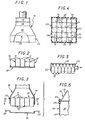
- la figure 1 est, avec un arrachement local, une vue en élévation d'un dispositif de préhension suivant l'invention;
- la figure 2 est une vue en élévation-coupe d'un lit d'objets susceptibles d'être saisis par un tel dispositif de préhension ;
- la figure 3 est une vue en élévation-coupe du dispositif de préhension suivant l'invention illustrant le mode d'intervention de celui-ci ;
- la figure 4 est une vue en coupe transversale de ce dispositif de préhension, suivant la ligne IV-IV de la figure 3 ;
- la figure 5 est une vue analogue à celle de la figure 3, pour une variante de réalisation ;
- la figure 6 est, à échelle supérieure, une vue partielle en élévation-coupe d'un dispositif de préhension suivant l'invention, suivant une autre forme de réalisation de celui-ci.
- Les figures 1 à 4 illustrent à titre d'exemple l'application de l'invention à la dépalettisation de
conteneurs 10, du genre bidons, qui, dans la forme de réalisation, ont une section transversale globalement carrée, à angles largement arrondis, et sont dotés, en partie supérieure, dans l'un des angles d'une telle section, d'un goulot excentré 11.
- Figure 1 is, with a local cutaway, an elevational view of a gripping device according to the invention;
- Figure 2 is an elevation-sectional view of a bed of objects capable of being grasped by such a gripping device;
- Figure 3 is an elevation-sectional view of the gripping device according to the invention illustrating the mode of intervention thereof;
- Figure 4 is a cross-sectional view of this gripping device, along the line IV-IV of Figure 3;
- Figure 5 is a view similar to that of Figure 3, for an alternative embodiment;
- Figure 6 is, on a larger scale, a partial elevational view in section of a gripping device according to the invention, according to another embodiment thereof.
- FIGS. 1 to 4 illustrate by way of example the application of the invention to the depalletization of
containers 10, of the canister type, which, in the embodiment, have a generally square cross-section, with widely rounded angles, and are provided, in the upper part, in one of the corners of such a section, with aneccentric neck 11.
De tels conteneurs 10 sont gerbés en lits superposés sur une quelconque palette, qui n'est pas représentée sur les figures, mais qui, à titre d'exemple, y est supposée être de contour globalement carré.
Seul un tel lit de conteneurs 10 est représenté à la figure 2, et, à titre d'exemple, il lui est associé, sur celle-ci, un intercalaire 12, en forme de barquette, destiné à le séparer du lit sous-jacent. Cet intercalaire n'est parfois qu'une simple feuille plane.Only such a
Au sein d'un tel lit, les conteneurs 10 sont disposés côte à côte, en étant juxtaposés deux à deux par leurs faces respectives.Within such a bed, the
Du fait notamment de l'arrondi de leur section, ils ménagent entre eux des passages 14, qui, pour plus de clarté, ont été matérialisés par des hachures à la figure 4.Due in particular to the roundness of their section, they provide between them
Du fait de leur excentration, les goulots 11 des conteneurs 10 se trouvent, en plan, pour le lit formé par ces conteneurs 10, disposés de manière aléatôire, suivant l'orientation angulaire relative des conteneurs 10.Due to their eccentricity, the
Il s'agit, pour la dépalettisation à assurer, de saisir simultanément l'ensemble des conteneurs 10 d'un même lit.It is, for the depalletization to be ensured, simultaneously gripping all the
Le dispositif de préhension 15 utilisé à cet effet suivant l'invention met en oeuvre, de manière connue en soi, une source d'aspiration.The
Il s'agit, par exemple, d'un ventilateur 16, dont on a schématisé en 17 l'ouïe de refoulement.This is, for example, a
Ce ventilateur 16 est disposé à la partie haute d'une hotte d'aspiration 18, avec intercalation, entre lui et celle-ci, dans l'exemple de'réalisation représenté, d'un dispositif de mise à l'air libre 19 convenablement commandé.This
Ces dispositions, sont bien connues par elles-mêmes, et ne relevant pas de la présente invention, elles ne seront pas décrites en détail ici.These provisions are well known in themselves, and not pertaining to the present invention, they will not be described in detail here.
Leur réalisation relève d'ailleurs simplement du domaine de l'homme de l'art.Their realization is moreover simply within the domain of those skilled in the art.
De manière également connue en soi, la hotte d'aspiration 18 est, dans la forme de réalisation représentée sur les figures 1 à 4, fermée, à sa base, par un fond perforé 20, adapté à former une barrière propre à la retenue mécanique des conteneurs à saisir à l'encontre de la source d'aspiration que constitue le ventilateur 16.In a manner also known per se, the
Il peut s'agir par exemple d'une tôle convenablement ajourée, d'un grillage, d'un réseau de fils, ou d'un quelconque autre organe formant barrière approprié.It may for example be a suitably perforated sheet, a mesh, a network of wires, or any other suitable barrier member.
Quoi qu'il en soit, le contour de la base de la hotte d'aspiration 18, et donc de son fond perforé 20, est à l'image de celui du lit de conteneurs 10 à saisir.Anyway, the outline of the base of the
Il s'agit donc, dans l'exemple de réalisation représenté, d'un contour globalement carré.It is therefore, in the illustrated embodiment, a generally square contour.
Suivant l'invention, le dispositif de préhension 15 comporte un moyen latéral de confinement ou jupe 22 par laquelle il est adapté à au moins pour partie coiffer latéralement l'ensemble du lit de conteneurs 10 à saisir.According to the invention, the
Tel que représenté sur les figures 1 à 4, il peut s'agir par exemple d'un simple prolongement vertical vers le bas, au-delà du fond perforé 20, des parois latérales de la hotte d'aspiration 18, qui forment globalement un tronc de pyramide.As shown in Figures 1 to 4, it may for example be a simple vertical extension downward, beyond the
Une telle jupe 22 est donc, dans ce cas, rigide.Such a
Quoi qu'il en soit, elle s'étend, en pratique, à la périphérie de la barrière de retenue mécanique que forme le fond perforé 20 de la hotte d'aspiration 18, et son contour est à l'image de celui de ce fond.Anyway, it extends, in practice, to the periphery of the mechanical retaining barrier formed by the
Suivant des dispositions, qui, ne faisant pas partie de la présente invention et ne relevant que du simple domaine de l'homme de l'art, ne seront pas décrites en détail ici, le dispositif de préhension 15 ainsi constitué est globalement monté mobile entre deux positions, l'une de prélèvement, l'autre de déchargement.According to provisions, which, not forming part of the present invention and pertaining only to the simple domain of a person skilled in the art, will not be described in detail here, the
Pour sa position de prélèvement, il coiffe latéralement l'ensemble du lit de conteneurs 10 à saisir, comme mentionné ci-dessus.For its picking position, it covers the
Autrement dit, pour cette position de prélèvement, la jupe 22 de ce dispositif de préhension 15 ceinture l'ensemble du lit de conteneurs 10 à saisir, comme illustré par les figures 3 et 4.In other words, for this sampling position, the
Une telle jupe 22, qui est en continuité avec la hotte d'aspiration 18, confine dès lors latéralement le cheminement de fuite laissé libre au fluide d'aspirationoSuch a
A la figure 4, et pour plus de clarté, comme précédemment, on a matérialisé par des hachures les passages 24 ainsi délimités par la jupe 22, entre celle-ci et ceux des conteneurs 10 qui sont à la périphérie du lit formé par l'ensemble de ces conteneurs 10.In FIG. 4, and for greater clarity, as before, the
Le dispositif de prélèvement 15 étant ainsi en position de prélèvement, on commande l'entrée en action de la source d'aspiration que constitue le ventilateur 16, et, suivant l'invention, on assure par celle-ci un débit d'aspiration suffisant pour établir, de part et d'autre de la section de passage formée par la différence entre, d'une part, la section totale de la jupe 22, et, d'autre part, la partie de celle-ci obturée par les conteneurs 10 concernés, la dépression nécessaire à l'entraînement de ceux-ci.The
Ainsi qu'on l'aura compris, cette section de passage est formée par les passages 14 et 24, précisés ci-dessus et matérialisés par des hachures à la figure 4.As will be understood, this passage section is formed by
Le dispositif de préhension 15 est alors commandé en déplacement, d'abord verticalement, puis, éventuellement, latéralement, jusqu'à sa position de déchargement.The
Du fait de la dépression engendrée par le ventilateur 16, les conteneurs 10 se trouvent entraînés, dans leur ensemble, sans qu'il soit nécessaire, comme dans l'art antérieur, qu'une quelconque dépression s'exerce individuellement à l'égard de chacun d'euxoDue to the vacuum generated by the
Cet entraînement est donc notamment indifférent à la localisation de leur goulot 11 vis-à-vis des perforations du fond 20 de la hotte d'aspiration 18.This training is therefore in particular indifferent to the location of their
Comme précisé ci-dessus, ce fond 20 n'a en l'espèce que pour simple but d'assurer une retenue mécanique des conteneurs 10 à l'égard de l'aspiration dont ils sont l'objet.As explained above, this
Si désiré, on assure par le ventilateur 16 constituant la source d'aspiration non seulement l'entraînement des conteneurs 10, comme décrit ci-dessus, mais encore à celui de l'intercalaire 12 sous-jacent à ceux-ci.If desired, the
Ultérieurement, au cours du déplacement du dispositif de préhension 15, une désolidarisation de cet intercalaire 12 vis-à-vis des conteneurs 10 est assurée par tout moyen approprié.Subsequently, during the movement of the
Par exemple, et tel qu'illustré à la figure 3, il peut s'agir de moyens mécaniques, tels que doigts 25,venant s'interposer sur le trajet suivi alors par l'intercalaire 12, pour la retenue de celui-ci. Son dégagement peut être progressif à partir de sa périphérie, en profitant de sa flexibilité.For example, and as illustrated in FIG. 3, it may be mechanical means, such as
Mais il peut s'agir également d'ajutages de soufflages, qui, portés par la hotte d'aspiration 18, sont propres à projeter en direction de l'intercalaire 12 un jet de fluide de nature à assurer la dépose recherchée pour celui-ci, ou, encore, de buses d'aspiration venant s'appliquer sur la face inférieure de cet intercalaire 12.But it may also be blowing nozzles, which, carried by the
Quoi qu'il en soit, lorsque le dispositif de préhension 15 est arrivé en position de dégagement, on procède à la suppression de la dépression notamment par au moins une des opérations suivantes : arrêt du ventilateur 16, entrée en action du dispositif de mise à l'air libre 19, ou fermeture de l'ouïe de refoulement 17.Anyway, when the
Les conteneurs 10 préalablement saisis par ce dispositif de préhension 15 sont alors relâchés par celui-ci.The
"Pour saisir les objets, tout en laissant en place le support sur lequel ils sont placés (intercalaire, table, etc...), ce dernier doit être ajouré en conséquence par tout moyen approprié soit par des perforations dans l'intercalaire, soit, dans le cas d'une table, et à titre d'exemple par des planches non jointives, une tôle perforée, etc..."."To grab objects, while leaving the support on which they are placed (interlayer, table, etc.), the latter must be perforated accordingly by any appropriate means, either by perforations in the interlayer, or , in the case of a table, and by way of example by non-contiguous planks, perforated sheet, etc ... ".
Le dispositif de préhension selon l'invention admet des fonds perforés 20 nettement plus ajourés que dans l'art antérieur. En effet, selon les procédés anciens tout trou n'aboutissant pas sur l'objet à saisir conduisait à des fuites et se révélait nuisible : on utilisait alors de faibles taux de perforation, toujours inférieurs à 50%. Au contraire selon la présente invention chaque trou participe à l'obtention de la dépression au-dessus des objets à saisir, et affaiblit de plus la perte de charge de part et d'autre de ce fond. Des taux de perforation élevés sont alors recommandés, pouvant avoisiner 100% ; le fond peut alors être constitué d'un grillage.The gripping device according to the invention admits
Dans ce qui précède, on a supposé que la source d'aspiration mise en oeuvre exerce ses effets sur les conteneurs 10 à travers un fond perforé.In the foregoing, it has been assumed that the suction source used exerts its effects on the
Il n'en est pas nécessairement ainsi, du fait de la présence suivant l'invention d'une jupe 22.This is not necessarily so, due to the presence according to the invention of a
Au contraire, et tel que schématiquement illustré à la figure 5, le raccordement de l'ouïe d'aspiration du ventilateur constituant la source d'aspiration peut, tel que schématisé par une flèche sur cette figure 5, se faire latéralement par rapport au volume délimité par la jupe 22 suivant l'invention et le fond 20 à la périphérie duquel elle est établie.On the contrary, and as schematically illustrated in FIG. 5, the connection of the suction opening of the fan constituting the suction source can, as shown diagrammatically by an arrow in this FIG. 5, be made laterally with respect to the volume delimited by the
Ce fond 20 peut dès lors être plein, sans une quelconque perforation.This bottom 20 can therefore be full, without any perforation.
Le dispositif de préhension correspondant s'en trouve simplifié, la hotte d'aspiration, notamment, se trouvant éliminée.The corresponding gripping device is simplified, the extraction hood, in particular, being eliminated.
Dans l'exemple d'application illustré par la figure 5, les conteneurs à saisir sont des bouteilles, supposées être à section circulaire par exemple.In the example of application illustrated by FIG. 5, the containers to be seized are bottles, supposed to be of circular section for example.
Dans ce qui précède, il a été supposé que la jupe 22 suivant l'invention était rigide, et qu'elle était rigidement fixée au dispositif de préhension 15 qu'elle équipe.In the foregoing, it has been assumed that the
Il n'en est pas nécessairement ainsi.This is not necessarily so.
Au contraire, si désiré, une telle jupe 22 peut au moins pour partie être mobile entre une configuration de prélèvement pour laquelle elle est apte à se plaquer latéralement contre une partie au moins de ceux des objets à saisir qui sont à la périphérie de l'ensemble formé par ceux-ci, et une configuration de déchargement pour laquelle elle est écartée desdits objets.On the contrary, if desired, such a
Par exemple, et tel que schématiquement illustré à la figure 6, l'une au moins des parois 27 d'une telle jupe 22, et, en pratique, chacune de celles-ci, forme un volet articulé par une charnière 28 à un axe de support 29 solidaire de la hotte d'aspiration 18 mise en oeuvre dans l'exemple de réalisation illustré par cette figure 6.For example, and as schematically illustrated in FIG. 6, at least one of the
Lorsque la source d'aspiration associée est en action, les parois 27 de la jupe 22 viennent se plaquer d'elles-mêmes contre les objets à saisir qui se trouvent à la périphérie de l'ensemble formé par ceux-ci.When the associated suction source is in action, the
Lorsque l'action de cette source d'aspiration est interrompue, elles sont libres de s'écarter desdits objets.When the action of this suction source is interrupted, they are free to move away from said objects.
Par exemple, il peut leur être associé à chacune un ressort à cet effet (non représenté sur la figure).For example, each of them may be associated with a spring for this purpose (not shown in the figure).
En variante, leur dégagement peut être assuré par simple gravité, si, par construction, leur axe de support 29 se trouve déporté latéralement par rapport à la périphérie de l'ensemble formé par les objets à saisir.Alternatively, their release can be ensured by simple gravity, if, by construction, their
Tel que décrit ci-dessus, les parois 27 de la jupe 22 peuvent encore être rigides.As described above, the
En variante, elles peuvent plus simplement être élastiquement déformables.Alternatively, they can more simply be elastically deformable.
La présente invention ne se limite d'ailleurs pas aux formes de réalisation et de mise en oeuvre décrites et représentées, mais englobe toute variante d'exécution et/ou de combinaison de leurs divers éléments.The present invention is moreover not limited to the embodiments and implementation described and shown, but encompasses any variant embodiment and / or combination of their various elements.
Il convient de souligner que l'organe 20 formant barrière pour la retenue mécanique de la charge à saisir joue un rôle fondamentalement différent des fonds perforés des dispositifs analogues de l'art antérieur. Si dans les deux cas il s'agit d'un arrêt mécanique des objets en direction de la source d'aspiration, dans l'art antérieur les surfaces de passage de l'écoulement d'air doivent être aussi réduites que possible pour éviter des fuites parasites, alors que selon l'invention on cherche au contraire à augmenter ces surfaces de passages, en tendant avantageusement vers 100%, tout en assurant l'arrêt des objets.It should be emphasized that the
Claims (8)
Applications Claiming Priority (2)
| Application Number | Priority Date | Filing Date | Title |
|---|---|---|---|
| FR8200290A FR2519619B1 (en) | 1982-01-11 | 1982-01-11 | SUCTION GRIPPING METHOD AND DEVICE |
| FR8200290 | 1982-01-11 |
Publications (2)
| Publication Number | Publication Date |
|---|---|
| EP0084479A1 true EP0084479A1 (en) | 1983-07-27 |
| EP0084479B1 EP0084479B1 (en) | 1986-03-19 |
Family
ID=9269860
Family Applications (1)
| Application Number | Title | Priority Date | Filing Date |
|---|---|---|---|
| EP83400050A Expired EP0084479B1 (en) | 1982-01-11 | 1983-01-10 | Process and device for gripping by means of air suction |
Country Status (10)
| Country | Link |
|---|---|
| EP (1) | EP0084479B1 (en) |
| BE (1) | BE895565A (en) |
| DE (1) | DE3362570D1 (en) |
| DK (1) | DK158091C (en) |
| ES (1) | ES8308797A1 (en) |
| FR (1) | FR2519619B1 (en) |
| GB (1) | GB2113178A (en) |
| GR (1) | GR77876B (en) |
| IE (1) | IE53864B1 (en) |
| IT (1) | IT1193605B (en) |
Cited By (5)
| Publication number | Priority date | Publication date | Assignee | Title |
|---|---|---|---|---|
| FR2579190A1 (en) * | 1985-03-21 | 1986-09-26 | Thibault Jacques | Device for lifting loads in layers formed of objects which are independent of one another and arranged side by side |
| EP0554592A1 (en) * | 1992-02-04 | 1993-08-11 | House Food Industrial Co., Ltd. | A suction-type robot hand |
| EP1162163A1 (en) * | 2000-06-08 | 2001-12-12 | SIG Pack Systems AG | Gripping device for articles and method for operating the same |
| WO2011135031A1 (en) * | 2010-04-28 | 2011-11-03 | Autefa Automation Gmbh | Layer gripping device and handling device |
| CN108573780A (en) * | 2018-06-19 | 2018-09-25 | 杭州良淋电子科技股份有限公司 | Flexible flat cable lineation machine |
Families Citing this family (5)
| Publication number | Priority date | Publication date | Assignee | Title |
|---|---|---|---|---|
| GB2157646A (en) * | 1984-04-19 | 1985-10-30 | Secr Defence | A vacuum gripper |
| GB8701347D0 (en) * | 1987-01-22 | 1987-02-25 | Bishop Barn Ltd | Package handling apparatus |
| US4753564A (en) * | 1987-01-23 | 1988-06-28 | Goldco Industries, Inc. | Apparatus and method for effecting movement of selected tiers of stacked articles using pressure differentials |
| DE3824155A1 (en) * | 1988-07-16 | 1990-01-25 | Focke & Co | DEVICE FOR LIFTING TRAY PACKS |
| DE4425003A1 (en) * | 1994-07-15 | 1996-01-18 | Hes Liselotte | Container packing and unpacking process, e.g. for bottles, glasses or cans |
Citations (11)
| Publication number | Priority date | Publication date | Assignee | Title |
|---|---|---|---|---|
| US1579744A (en) * | 1925-06-03 | 1926-04-06 | Francis M Aday | Vacuum lifting device |
| US2390242A (en) * | 1945-03-01 | 1945-12-04 | H M Seippel | Article transferring apparatus |
| DE1075814B (en) * | 1955-07-11 | 1960-02-18 | P Ballantine £x Sons Newark, N J (V St A) | Hollow suction head for conveying stacked goods |
| US3404787A (en) * | 1966-12-27 | 1968-10-08 | American Chain & Cable Co | Suction lift for article distribution and storage system |
| GB1137031A (en) * | 1965-04-03 | 1968-12-18 | Hebel Gasbetonwerk Gmbh | Method and apparatus for the casting, lifting and setting of plastic mass blocks, inparticular porous concrete blocks |
| DE1930366A1 (en) * | 1968-06-17 | 1969-12-18 | Nat Res Dev | Device for lifting objects by means of negative pressure |
| DE1926479A1 (en) * | 1969-05-23 | 1970-12-03 | Carlo Schaberger Sondermaschb | Device for grasping, lifting and moving open containers such as bottles, cans, etc. |
| FR2166242A1 (en) * | 1972-01-03 | 1973-08-17 | Applic Procedes Electriq | |
| FR2184072A1 (en) * | 1972-05-10 | 1973-12-21 | Laessig Foerdertech Hamburg | |
| FR2316177A1 (en) * | 1975-07-02 | 1977-01-28 | Marryat Handling Ltd | Suction head for lifting and handling load - has restrictor and flexible curtains with centraliser to accommodate different size loads |
| GB1483952A (en) * | 1975-10-27 | 1977-08-24 | Smedley Hp Foods Ltd | Load handling |
-
1982
- 1982-01-11 FR FR8200290A patent/FR2519619B1/en not_active Expired
-
1983
- 1983-01-10 DK DK006783A patent/DK158091C/en active
- 1983-01-10 GR GR70227A patent/GR77876B/el unknown
- 1983-01-10 DE DE8383400050T patent/DE3362570D1/en not_active Expired
- 1983-01-10 EP EP83400050A patent/EP0084479B1/en not_active Expired
- 1983-01-10 BE BE0/209866A patent/BE895565A/en not_active IP Right Cessation
- 1983-01-11 ES ES518904A patent/ES8308797A1/en not_active Expired
- 1983-01-11 IT IT19059/83A patent/IT1193605B/en active
- 1983-01-11 IE IE53/83A patent/IE53864B1/en not_active IP Right Cessation
- 1983-01-11 GB GB08300586A patent/GB2113178A/en not_active Withdrawn
Patent Citations (11)
| Publication number | Priority date | Publication date | Assignee | Title |
|---|---|---|---|---|
| US1579744A (en) * | 1925-06-03 | 1926-04-06 | Francis M Aday | Vacuum lifting device |
| US2390242A (en) * | 1945-03-01 | 1945-12-04 | H M Seippel | Article transferring apparatus |
| DE1075814B (en) * | 1955-07-11 | 1960-02-18 | P Ballantine £x Sons Newark, N J (V St A) | Hollow suction head for conveying stacked goods |
| GB1137031A (en) * | 1965-04-03 | 1968-12-18 | Hebel Gasbetonwerk Gmbh | Method and apparatus for the casting, lifting and setting of plastic mass blocks, inparticular porous concrete blocks |
| US3404787A (en) * | 1966-12-27 | 1968-10-08 | American Chain & Cable Co | Suction lift for article distribution and storage system |
| DE1930366A1 (en) * | 1968-06-17 | 1969-12-18 | Nat Res Dev | Device for lifting objects by means of negative pressure |
| DE1926479A1 (en) * | 1969-05-23 | 1970-12-03 | Carlo Schaberger Sondermaschb | Device for grasping, lifting and moving open containers such as bottles, cans, etc. |
| FR2166242A1 (en) * | 1972-01-03 | 1973-08-17 | Applic Procedes Electriq | |
| FR2184072A1 (en) * | 1972-05-10 | 1973-12-21 | Laessig Foerdertech Hamburg | |
| FR2316177A1 (en) * | 1975-07-02 | 1977-01-28 | Marryat Handling Ltd | Suction head for lifting and handling load - has restrictor and flexible curtains with centraliser to accommodate different size loads |
| GB1483952A (en) * | 1975-10-27 | 1977-08-24 | Smedley Hp Foods Ltd | Load handling |
Cited By (7)
| Publication number | Priority date | Publication date | Assignee | Title |
|---|---|---|---|---|
| FR2579190A1 (en) * | 1985-03-21 | 1986-09-26 | Thibault Jacques | Device for lifting loads in layers formed of objects which are independent of one another and arranged side by side |
| EP0554592A1 (en) * | 1992-02-04 | 1993-08-11 | House Food Industrial Co., Ltd. | A suction-type robot hand |
| US5388879A (en) * | 1992-02-04 | 1995-02-14 | House Food Industrial Co., Ltd. | Suction type robot hand |
| EP1162163A1 (en) * | 2000-06-08 | 2001-12-12 | SIG Pack Systems AG | Gripping device for articles and method for operating the same |
| US6554336B2 (en) | 2000-06-08 | 2003-04-29 | Sig Pack Systems Ag | Method and apparatus for grasping items |
| WO2011135031A1 (en) * | 2010-04-28 | 2011-11-03 | Autefa Automation Gmbh | Layer gripping device and handling device |
| CN108573780A (en) * | 2018-06-19 | 2018-09-25 | 杭州良淋电子科技股份有限公司 | Flexible flat cable lineation machine |
Also Published As
| Publication number | Publication date |
|---|---|
| GB8300586D0 (en) | 1983-02-09 |
| EP0084479B1 (en) | 1986-03-19 |
| DK6783A (en) | 1983-07-12 |
| ES518904A0 (en) | 1983-10-16 |
| DK6783D0 (en) | 1983-01-10 |
| ES8308797A1 (en) | 1983-10-16 |
| FR2519619A1 (en) | 1983-07-18 |
| IE830053L (en) | 1983-07-11 |
| DK158091C (en) | 1990-09-10 |
| DK158091B (en) | 1990-03-26 |
| IT8319059A0 (en) | 1983-01-11 |
| BE895565A (en) | 1983-05-02 |
| DE3362570D1 (en) | 1986-04-24 |
| GR77876B (en) | 1984-09-25 |
| IT1193605B (en) | 1988-07-21 |
| FR2519619B1 (en) | 1986-02-21 |
| IE53864B1 (en) | 1989-03-29 |
| GB2113178A (en) | 1983-08-03 |
Similar Documents
| Publication | Publication Date | Title |
|---|---|---|
| EP1095605B1 (en) | Ejecting apparatus for cartridge | |
| EP1127811B1 (en) | Receptacle with reduced noise of the lid during its closing movement | |
| EP0084479A1 (en) | Process and device for gripping by means of air suction | |
| FR2633265A1 (en) | DEVICE FOR THE GRIPPING OF ISOLATED OR ADJACENT FLEXIBLE PARTS, THEIR HANDLING AND REMOVAL, IN PARTICULAR FROM LEATHER PIECES AND THE LIKE | |
| EP0530426A1 (en) | Grasping and transfer gripper | |
| FR2736576A1 (en) | DEVICE FOR REMOVING CUT AND STACKED PARTS | |
| FR3048422B1 (en) | PALETTE PRETENSION | |
| FR2676718A1 (en) | DEVICE FOR SEPARATING STACKED SHEETS. | |
| FR2827264A1 (en) | DEVICE FOR SEPARATING PREFERABLY FLAT OBJECTS FROM PRINTING PLATES | |
| CA2132803C (en) | Device for grasping flat objects and device for destacking equipped with such grasping device | |
| FR2579190A1 (en) | Device for lifting loads in layers formed of objects which are independent of one another and arranged side by side | |
| CA2132801C (en) | Device for separating two objects grasped together and device for destacking flat objects equipped with such separating device | |
| EP2456691B1 (en) | Collection truck for emptying waste collection receptacles | |
| EP0435774B1 (en) | Device for loading and unloading a storage cassette with flat objects | |
| FR2831879A1 (en) | Individualization device for removing disc shaped blanks comprises two parallel vacuum grippers controlled so that one gripper sucks blank to raised position whilst second gripper supports blank on opposite side | |
| FR2673612A1 (en) | Device for destacking and automatic dispensing of trays | |
| FR2810961A1 (en) | AUTOMATIC PART DISTRIBUTION DEVICE BY INCLINED ROTARY SYSTEM WITH FINGERPRINTS | |
| FR2631924A1 (en) | Automatic method for installing a stretchable sleeve tube for labelling plastic or metal packages and device for implementing this method | |
| FR2615840A1 (en) | DEVICE FOR DEPILING RELATIVELY FLAT OBJECTS, SUCH AS LETTERS OR POSTAL PLATES | |
| CA2132800C (en) | Flat object supply magazine and flat object unstacking device equipped with such magazine | |
| FR2478047A1 (en) | DEVICE FOR HANDLING MATERIAL IN THE PLATE FORM | |
| EP0633215A1 (en) | Mechanical fall-preventing system for a heavy load gripping device | |
| EP0562197B1 (en) | Method and device for palletizing parcels | |
| FR2570064A1 (en) | Stacked fabric removal | |
| EP0704374B1 (en) | Machine for filling boxes |
Legal Events
| Date | Code | Title | Description |
|---|---|---|---|
| PUAI | Public reference made under article 153(3) epc to a published international application that has entered the european phase |
Free format text: ORIGINAL CODE: 0009012 |
|
| AK | Designated contracting states |
Designated state(s): BE DE GB IT LU NL |
|
| RHK1 | Main classification (correction) |
Ipc: B66C 1/02 |
|
| 17P | Request for examination filed |
Effective date: 19830930 |
|
| GRAA | (expected) grant |
Free format text: ORIGINAL CODE: 0009210 |
|
| AK | Designated contracting states |
Kind code of ref document: B1 Designated state(s): BE DE GB IT LU NL |
|
| REF | Corresponds to: |
Ref document number: 3362570 Country of ref document: DE Date of ref document: 19860424 |
|
| ITF | It: translation for a ep patent filed |
Owner name: JACOBACCI & PERANI S.P.A. |
|
| PLBE | No opposition filed within time limit |
Free format text: ORIGINAL CODE: 0009261 |
|
| STAA | Information on the status of an ep patent application or granted ep patent |
Free format text: STATUS: NO OPPOSITION FILED WITHIN TIME LIMIT |
|
| 26N | No opposition filed | ||
| ITTA | It: last paid annual fee | ||
| EPTA | Lu: last paid annual fee | ||
| PGFP | Annual fee paid to national office [announced via postgrant information from national office to epo] |
Ref country code: LU Payment date: 19941201 Year of fee payment: 13 |
|
| PGFP | Annual fee paid to national office [announced via postgrant information from national office to epo] |
Ref country code: DE Payment date: 19941215 Year of fee payment: 13 |
|
| PGFP | Annual fee paid to national office [announced via postgrant information from national office to epo] |
Ref country code: GB Payment date: 19941216 Year of fee payment: 13 |
|
| PGFP | Annual fee paid to national office [announced via postgrant information from national office to epo] |
Ref country code: BE Payment date: 19941222 Year of fee payment: 13 |
|
| PGFP | Annual fee paid to national office [announced via postgrant information from national office to epo] |
Ref country code: NL Payment date: 19950131 Year of fee payment: 13 |
|
| PG25 | Lapsed in a contracting state [announced via postgrant information from national office to epo] |
Ref country code: LU Free format text: LAPSE BECAUSE OF NON-PAYMENT OF DUE FEES Effective date: 19960110 Ref country code: GB Effective date: 19960110 |
|
| PG25 | Lapsed in a contracting state [announced via postgrant information from national office to epo] |
Ref country code: BE Effective date: 19960131 |
|
| BERE | Be: lapsed |
Owner name: CARNAUD EMBALLAGE Effective date: 19960131 |
|
| PG25 | Lapsed in a contracting state [announced via postgrant information from national office to epo] |
Ref country code: NL Effective date: 19960801 |
|
| GBPC | Gb: european patent ceased through non-payment of renewal fee |
Effective date: 19960110 |
|
| NLV4 | Nl: lapsed or anulled due to non-payment of the annual fee |
Effective date: 19960801 |
|
| PG25 | Lapsed in a contracting state [announced via postgrant information from national office to epo] |
Ref country code: DE Effective date: 19961001 |