EP0554592A1 - A suction-type robot hand - Google Patents
A suction-type robot hand Download PDFInfo
- Publication number
- EP0554592A1 EP0554592A1 EP92300946A EP92300946A EP0554592A1 EP 0554592 A1 EP0554592 A1 EP 0554592A1 EP 92300946 A EP92300946 A EP 92300946A EP 92300946 A EP92300946 A EP 92300946A EP 0554592 A1 EP0554592 A1 EP 0554592A1
- Authority
- EP
- European Patent Office
- Prior art keywords
- suction
- suction pad
- robot hand
- type robot
- pad
- Prior art date
- Legal status (The legal status is an assumption and is not a legal conclusion. Google has not performed a legal analysis and makes no representation as to the accuracy of the status listed.)
- Granted
Links
Images


Classifications
-
- B—PERFORMING OPERATIONS; TRANSPORTING
- B25—HAND TOOLS; PORTABLE POWER-DRIVEN TOOLS; MANIPULATORS
- B25J—MANIPULATORS; CHAMBERS PROVIDED WITH MANIPULATION DEVICES
- B25J15/00—Gripping heads and other end effectors
- B25J15/06—Gripping heads and other end effectors with vacuum or magnetic holding means
- B25J15/0616—Gripping heads and other end effectors with vacuum or magnetic holding means with vacuum
-
- Y—GENERAL TAGGING OF NEW TECHNOLOGICAL DEVELOPMENTS; GENERAL TAGGING OF CROSS-SECTIONAL TECHNOLOGIES SPANNING OVER SEVERAL SECTIONS OF THE IPC; TECHNICAL SUBJECTS COVERED BY FORMER USPC CROSS-REFERENCE ART COLLECTIONS [XRACs] AND DIGESTS
- Y10—TECHNICAL SUBJECTS COVERED BY FORMER USPC
- Y10S—TECHNICAL SUBJECTS COVERED BY FORMER USPC CROSS-REFERENCE ART COLLECTIONS [XRACs] AND DIGESTS
- Y10S294/00—Handling: hand and hoist-line implements
- Y10S294/907—Sensor controlled device
Definitions
- This invention relates generally to a suction-type robot hand and more particularly to a suction-type robot hand adapted to suck and transfer fragile articles such as a fried cutlet, a roasted bean curd, a bread and the like to a desired place.
- robot hands Other types of robot hands are disclosed, for example, in Japanese Patent Disclosure Nos. 64-8141 and 63-283884 wherein a suction pad mounted on a robot hand is adapted to suck articles or materials and transferring them to a desired place.
- a suction hand has a grid at a predetermined depth from an opening thereof so as to suck a bag without forming crinkle thereon.
- a suction-type robot hand comprising (a) a suction pad having a gas-permeable obstacle at an opening of the suction pad ; and (b) a main body of the robot hand supporting the suction pad and having a vacuum passage communicating with the suction pad.
- the provision of the gas-permeable obstacle at the opening of the suction pad makes it possible to suck fragile articles on the opening and the obstacle without breaking them and transfer them at once to a desired place.
- a suction-type robot hand 1 of the present invention is adapted to be mounted on a main body (not shown) of a robot and has a suction pad 2 and a main body 3 of the robot hand 1.
- the configuration of the suction pad 2 shown in Fig. 2 is cylindrical. However it has no need to make it cylindrical and may be any other configuration such as prism, cone, pyramid and the like. There is also no limitation to the material of the suction pad 2 and it may be formed by suitable material such as rubber, synthetic resin and the like.
- the suction pad 2 has a net 5 which is positioned at an opening 4 of the suction pad 2. Accordingly, the fragile article is sucked on the opening 4 and the net 5 without breaking the fragile article by suction because there is not applied large suction pressure to the article at a center of the opening 4.
- the robot hand 3 has a pressure detector 13 close to the suction pad 2.
- the pressure detector 13 is conneted with a control apparatus 15 so that the suction pressure in the suction pad 2 is controlled in accordance with the output of the detector 13 so as to appropriately keep the suction pressure in the section pad 2.
- the net 5 may be replaced by a cross grid 20 shown in Fig. 2 (B) and a linear grid 22 shown in Fig. 2 (C) which are formed integrally with a main body of the suction pad 2.
- the suction pad 2 is supported by the main body 3 of the robot hand 1 at the forward end thereof.
- a vacuum passage 6 is formed within the main body 3 of the robot hand 1 and one end of the vacuum passage 6 is communicated with the inside of the suction pad 2.
- the other end of the vacuum passage 6 is communicated with a tank 9 through a first vacuum pipe 7 and a first connecting pipe 8.
- the tank 9 is led to a pump 12 through a second connecting pipe 10 and a second vacuum pipe 11.
- the tank 9 serves to hold therein water or debris of fragile articles entrained by the sucked air and to prevent them from being led to the pump 12. With sufficient reduction of pressure within the tank 9 prior to the suction operation by the suction pad 2, it is possible to efficiently achieve the suction of articles in a short time.
- the first vacuum pipe 7 has flexibility and length sufficiently accomodated to the motion of the robot.
- the first connecting pipe 8 is provided with a first ball valve 14a and a second ball valve 14b.
- the air flow rate in this case shoud at least satisfy a following relation: (degree of vacuum) ⁇ (area of the opening of the suction pad) > (estimated maximum weight of the predetermined amount of the objective particles)
- the left side of the above expression indicates the suction force for elevating the objective particles.
- the vacuum obtained by the pump 12 is led to the inside of the suction pad 2 through the second vacuum pipe 11, the second connecting pipe 10, the tank 9, the first connecting pipe 8, the first vacuum pipe 7 and the vacuum passage 6 of the main body 3 of the robot hand 1. This results in that the fragile article is sucked on the opening 4 of the suction pad 2 and the net 5.
- the other embodiment of a pad has a plurality of projections 30 which are circularly located on the opening, without any clearance.
- Each projection 30 has a thin portion, at its lower position so that they are inwardly bent by the suction in the pad 2.
- the projections 30 may be formed by making a plurality of cuts 40 on a cylindrical member, which are parallel to an axis of the cylindrical member.
Landscapes
- Engineering & Computer Science (AREA)
- Robotics (AREA)
- Mechanical Engineering (AREA)
- Manipulator (AREA)
Abstract
Description
- This invention relates generally to a suction-type robot hand and more particularly to a suction-type robot hand adapted to suck and transfer fragile articles such as a fried cutlet, a roasted bean curd, a bread and the like to a desired place.
- It is known a robot hand of the prior art, for example, from Japanese Patent Disclosure No. 63-251186 which uses two fingers for gripping articles or materials and transferring them to a desired place.
- Other types of robot hands are disclosed, for example, in Japanese Patent Disclosure Nos. 64-8141 and 63-283884 wherein a suction pad mounted on a robot hand is adapted to suck articles or materials and transferring them to a desired place.
- Other type of robot hand is disclosed in Japanese Utility Model Disclosure No. 61-58084 wherein a suction hand has a grid at a predetermined depth from an opening thereof so as to suck a bag without forming crinkle thereon.
- However none of the robot hands mentioned above can at once grip fragile articles such as a fried cutlet, a roasted bean curd, a piece of bread and the like to a desired place.
- It is therefore an object of the present invention to provide a robot hand which can grip and transfer a fragile articles at once without breaking the articles.
- The object of the present invention can be achieved by a suction-type robot hand comprising (a) a suction pad having a gas-permeable obstacle at an opening of the suction pad ; and (b) a main body of the robot hand supporting the suction pad and having a vacuum passage communicating with the suction pad.
- According to the robot hand of the present invention, the provision of the gas-permeable obstacle at the opening of the suction pad makes it possible to suck fragile articles on the opening and the obstacle without breaking them and transfer them at once to a desired place.
- Other objects and advantages of the present invention will become apparent from the following detailed description of a preferred embodiment of the present invention taken with reference to the accompanying drawings in which:
- Fig. 1 is an explanatory schematic view of a preferred embodiment of a suction-type robot hand of the present invention;
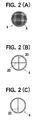
- Fig. 2 is a bottom view of a suction pad of the robot hand shown in Fig. 1; and,
- Fig. 3 is a perspective view of the suction pad having a plurality of flexible projections on an opening of thereof.
- As shown in Fig. 1 a suction-
type robot hand 1 of the present invention is adapted to be mounted on a main body (not shown) of a robot and has asuction pad 2 and amain body 3 of therobot hand 1. - The configuration of the
suction pad 2 shown in Fig. 2 is cylindrical. However it has no need to make it cylindrical and may be any other configuration such as prism, cone, pyramid and the like. There is also no limitation to the material of thesuction pad 2 and it may be formed by suitable material such as rubber, synthetic resin and the like. - The
suction pad 2 has anet 5 which is positioned at an opening 4 of thesuction pad 2. Accordingly, the fragile article is sucked on theopening 4 and the net 5 without breaking the fragile article by suction because there is not applied large suction pressure to the article at a center of theopening 4. - The
robot hand 3 has apressure detector 13 close to thesuction pad 2. Thepressure detector 13 is conneted with acontrol apparatus 15 so that the suction pressure in thesuction pad 2 is controlled in accordance with the output of thedetector 13 so as to appropriately keep the suction pressure in thesection pad 2. - The
net 5 may be replaced by across grid 20 shown in Fig. 2 (B) and a linear grid 22 shown in Fig. 2 (C) which are formed integrally with a main body of thesuction pad 2. - The
suction pad 2 is supported by themain body 3 of therobot hand 1 at the forward end thereof. Avacuum passage 6 is formed within themain body 3 of therobot hand 1 and one end of thevacuum passage 6 is communicated with the inside of thesuction pad 2. The other end of thevacuum passage 6 is communicated with atank 9 through afirst vacuum pipe 7 and a first connectingpipe 8. - The
tank 9 is led to apump 12 through a second connectingpipe 10 and asecond vacuum pipe 11. Thetank 9 serves to hold therein water or debris of fragile articles entrained by the sucked air and to prevent them from being led to thepump 12. With sufficient reduction of pressure within thetank 9 prior to the suction operation by thesuction pad 2, it is possible to efficiently achieve the suction of articles in a short time. - The
first vacuum pipe 7 has flexibility and length sufficiently accomodated to the motion of the robot. In addition, the first connectingpipe 8 is provided with afirst ball valve 14a and asecond ball valve 14b. - Then the operation of the suction-
type robot hand 1 of the present invention will be explained. Firstly setting theball valve 14a closed and theball valve 14b opened. Then energizing the robot and moving thesuction pad 2 toward above the objective articles. - Then energizing the
pump 12 and commencing the suction at a constant air flow rate. The air flow rate in this case shoud at least satisfy a following relation:

The left side of the above expression indicates the suction force for elevating the objective particles. - The vacuum obtained by the
pump 12 is led to the inside of thesuction pad 2 through thesecond vacuum pipe 11, the second connectingpipe 10, thetank 9, the first connectingpipe 8, thefirst vacuum pipe 7 and thevacuum passage 6 of themain body 3 of therobot hand 1. This results in that the fragile article is sucked on the opening 4 of thesuction pad 2 and the net 5. - Then moving the robot toward an objective place with the fragile articles sucked within the
suction pad 2. - Finally the
ball valve 14b is closed and theball valve 14a is opened. This causes introduction of the ambient air to the inside of thesuction pad 2 through the first connectingpipe 8, thefirst vacuum pipe 7 and thevacuum passage 6 of themain body 3 of therobot hand 1. Thus the suction force is vanished from thesuction pad 2 and the particles are released from thesuction pad 2 onto the predetermined objective place. In this case, it would be possible to more rapidly release the particles from thesuction pad 2 if pressurized air is supplied from an air source (not shown) connected to theball valve 14a. - The other embodiment of a pad, as shown in Figure 3, has a plurality of
projections 30 which are circularly located on the opening, without any clearance. Eachprojection 30 has a thin portion, at its lower position so that they are inwardly bent by the suction in thepad 2. In accordance with the present embodiment, even though a surface of the article is not plane, it is possible to grasp the article by thepad 2 quickly and without breaking the article. Theprojections 30 may be formed by making a plurality ofcuts 40 on a cylindrical member, which are parallel to an axis of the cylindrical member.
Claims (6)
- A suction-type robot hand comprising (a) a hollow suction pad having a gas-permeable obstacle at an opening of the suction pad ; and (b) a main body of the robot hand supporting the suction pad and having a vacuum passage communicating with the suction pad.
- The suction-type robot hand of claim 1 in which the gas-permeable obstacle is a net.
- The suction-type robot hand of claim 1 in which the gas-permeable obstacle is a cross grid formed integrally with the main body of the suction pad.
- The suction-type robot hand of claim 1 in which the gas-permeable obstacle is a linear grid formed integrally with the main body of the suction pad.
- The suction-type robot hand of claim 1 in which further has pressure deterctor for detecting suction pressure in the suction hand and suction adjusting means for adjusting pressure in the suction pad in accordance with an output of the pressure detector.
- The suction-type robot hand of claim 1 which a plurality of flexible projections are provided at the opening of the suction pad without clearance.
Priority Applications (3)
| Application Number | Priority Date | Filing Date | Title |
|---|---|---|---|
| DE1992606775 DE69206775T2 (en) | 1992-02-04 | 1992-02-04 | Suction pads for robots |
| EP92300946A EP0554592B1 (en) | 1992-02-04 | 1992-02-04 | A suction-type robot hand |
| US08/128,256 US5388879A (en) | 1992-02-04 | 1993-09-28 | Suction type robot hand |
Applications Claiming Priority (2)
| Application Number | Priority Date | Filing Date | Title |
|---|---|---|---|
| EP92300946A EP0554592B1 (en) | 1992-02-04 | 1992-02-04 | A suction-type robot hand |
| US08/128,256 US5388879A (en) | 1992-02-04 | 1993-09-28 | Suction type robot hand |
Publications (2)
| Publication Number | Publication Date |
|---|---|
| EP0554592A1 true EP0554592A1 (en) | 1993-08-11 |
| EP0554592B1 EP0554592B1 (en) | 1995-12-13 |
Family
ID=26131943
Family Applications (1)
| Application Number | Title | Priority Date | Filing Date |
|---|---|---|---|
| EP92300946A Expired - Lifetime EP0554592B1 (en) | 1992-02-04 | 1992-02-04 | A suction-type robot hand |
Country Status (2)
| Country | Link |
|---|---|
| US (1) | US5388879A (en) |
| EP (1) | EP0554592B1 (en) |
Cited By (4)
| Publication number | Priority date | Publication date | Assignee | Title |
|---|---|---|---|---|
| ES2114465A1 (en) * | 1994-04-06 | 1998-05-16 | Huertas Jose Maria Ruiz | Improvements to the subject of main patent No. P9400725 for machine for preparing and selling hot (toasted) sandwiches |
| FR3005887A1 (en) * | 2013-05-24 | 2014-11-28 | Arbor | PRE-TOOL FOR PRODUCTS, IN PARTICULAR FRESH FOOD PRODUCTS |
| WO2014202998A1 (en) * | 2013-06-21 | 2014-12-24 | Medical Research Council | Specimen handling device |
| CN108406831A (en) * | 2018-02-08 | 2018-08-17 | 江西新能源科技职业学院 | Flexible crawl mechanical arm |
Families Citing this family (8)
| Publication number | Priority date | Publication date | Assignee | Title |
|---|---|---|---|---|
| JPH07145535A (en) * | 1993-11-17 | 1995-06-06 | Nippon Felt Co Ltd | Cop changing device for weaving machine |
| EP0992183A1 (en) * | 1998-04-28 | 2000-04-12 | Assembléon N.V. | Component-handling machine |
| ATE375946T1 (en) * | 2000-06-08 | 2007-11-15 | Bosch Gmbh Robert | GRIPPER DEVICE FOR CAPTUREING OBJECTS AND METHOD FOR OPERATING THE SAME |
| DE10224598C1 (en) * | 2002-06-04 | 2003-07-17 | Gerhard Fuerst | Gripper for handling bagged bulk goods has suction pipe and gripper head with air sealed flexible shell to engage bulk goods sack |
| US7018161B2 (en) * | 2004-06-18 | 2006-03-28 | Blueprint Automation B.V. | Suction head |
| ATE549129T1 (en) | 2007-04-26 | 2012-03-15 | Adept Technology Inc | VACUUM GRIPPER |
| NO327666B1 (en) * | 2007-08-28 | 2009-09-07 | Optimove As | Vacuum gripping device and a method for machine handling of objects |
| US9950907B2 (en) | 2013-10-09 | 2018-04-24 | Columbia Insurance Company | Lifting methods, assemblies and systems |
Citations (7)
| Publication number | Priority date | Publication date | Assignee | Title |
|---|---|---|---|---|
| GB1216630A (en) * | 1969-06-16 | 1970-12-23 | Ind Beratung Anstalt | Cup for lifting full sacks by means of a vacuum |
| US3796455A (en) * | 1972-09-05 | 1974-03-12 | Unimation Inc | Air flow actuated overhead pickup device for limp sheet materials |
| EP0084479A1 (en) * | 1982-01-11 | 1983-07-27 | Carnaud Emballage | Process and device for gripping by means of air suction |
| EP0104871A2 (en) * | 1982-09-21 | 1984-04-04 | Fujitsu Limited | Supporting device |
| US4582353A (en) * | 1983-06-17 | 1986-04-15 | Pont-A-Mousson S.A. | Suction cup for gripping small, delicate objects |
| DE3518640A1 (en) * | 1985-05-23 | 1986-11-27 | Neider, Carmen, 8904 Friedberg | Sucker |
| EP0260128A2 (en) * | 1986-09-09 | 1988-03-16 | Kabushiki Kaisha Yakult Honsha | Vacuum suction device |
Family Cites Families (33)
| Publication number | Priority date | Publication date | Assignee | Title |
|---|---|---|---|---|
| US1364229A (en) * | 1919-10-17 | 1921-01-04 | Keyes Fibre Co | Sucker-head for pulp-molding machines |
| US1930778A (en) * | 1929-07-25 | 1933-10-17 | Michael J Skidelsky | Vacuum clothes brush |
| US2290916A (en) * | 1939-05-12 | 1942-07-28 | Hercules Powder Co Ltd | Packing machine |
| US2916059A (en) * | 1958-02-18 | 1959-12-08 | Lan J Wong | Evacuation valve cup |
| US3227299A (en) * | 1963-02-20 | 1966-01-04 | Elwell Parker Electric Co | Mechanical and vacuum operated roll handling apparatus |
| US3219380A (en) * | 1963-10-02 | 1965-11-23 | Yale & Towne Inc | Vacuum system for load handling |
| US3318468A (en) * | 1964-08-19 | 1967-05-09 | Hyster Co | Vacuum type load handling mechanism |
| US3294434A (en) * | 1965-02-08 | 1966-12-27 | William L Sinn | Gold leaf placing device |
| US3387718A (en) * | 1966-03-10 | 1968-06-11 | Alvey Conveyor Mfg Company | Pallet loading and unloading apparatus |
| CH455201A (en) * | 1967-06-08 | 1968-06-28 | Ind Beratung Anstalt | Suction cup for vacuum lifting of full bags |
| US3627369A (en) * | 1969-10-10 | 1971-12-14 | Charles H Nixon | High-temperature vacuum pickup |
| CA942346A (en) * | 1970-03-13 | 1974-02-19 | Federico Capetti | Suction device for picking up sheets |
| JPS4944149B1 (en) * | 1970-08-12 | 1974-11-26 | ||
| CH526461A (en) * | 1971-02-10 | 1972-08-15 | Gis Ag | Vacuum lifting device |
| US3826381A (en) * | 1972-03-30 | 1974-07-30 | Emhart Corp | Article handling apparatus |
| US3999795A (en) * | 1975-12-17 | 1976-12-28 | American Chain & Cable Company, Inc. | Vacuum pad system |
| US4006929A (en) * | 1975-12-17 | 1977-02-08 | American Chain & Cable Company, Inc. | Vacuum pad |
| GB1546086A (en) * | 1976-04-20 | 1979-05-16 | Metal Box Co Ltd | Method and apparatus for picking-up articles |
| JPS5813315B2 (en) * | 1979-05-01 | 1983-03-12 | 株式会社 妙徳製作所 | Vacuum suction gripping device |
| SU992381A1 (en) * | 1980-05-20 | 1983-01-30 | За витель | Vacuum load-engaging device |
| US4505505A (en) * | 1983-07-13 | 1985-03-19 | Airtec Industries | Vacuum device for lifting an article loosely wrapped in flexible film |
| IT1176164B (en) * | 1984-05-22 | 1987-08-18 | Bini & C Srl | PROCEDURE AND EQUIPMENT FOR LIFTING AND TRANSPORTING OBJECTS PLACED ON TRAY OR SIMILAR SUPPORTS |
| JPS6158084A (en) * | 1984-08-29 | 1986-03-25 | Hitachi Ltd | Device with label of image signal |
| US4750768A (en) * | 1986-05-14 | 1988-06-14 | Kumar V Sam | Gripper device |
| GB8701347D0 (en) * | 1987-01-22 | 1987-02-25 | Bishop Barn Ltd | Package handling apparatus |
| JPS63251186A (en) * | 1987-04-08 | 1988-10-18 | 富士通株式会社 | Hand for robot |
| JPS63283884A (en) * | 1987-05-18 | 1988-11-21 | 株式会社日立製作所 | Suction type robot hand |
| JPS648141A (en) * | 1987-07-01 | 1989-01-12 | Matsushita Electric Ind Co Ltd | Suction pad |
| IT1222456B (en) * | 1987-08-06 | 1990-09-05 | Enzo Scaglia | SUCTION CUP LIFT |
| JPH01281231A (en) * | 1987-10-22 | 1989-11-13 | Fujitsu Ltd | Testpiece holding device |
| SU1576465A1 (en) * | 1988-04-26 | 1990-07-07 | Центральное Проектно-Конструкторское И Технологическое Бюро "Росагропромтехпроект" | Vacuum grip |
| NL8900259A (en) * | 1989-02-02 | 1990-09-03 | Stork Amsterdam | Gripping suction cup - has highly-flexible protruding seal fitting against protruding or uneven surfaces |
| JPH0386488A (en) * | 1989-08-29 | 1991-04-11 | Jamco Corp | Suction device |
-
1992
- 1992-02-04 EP EP92300946A patent/EP0554592B1/en not_active Expired - Lifetime
-
1993
- 1993-09-28 US US08/128,256 patent/US5388879A/en not_active Expired - Fee Related
Patent Citations (7)
| Publication number | Priority date | Publication date | Assignee | Title |
|---|---|---|---|---|
| GB1216630A (en) * | 1969-06-16 | 1970-12-23 | Ind Beratung Anstalt | Cup for lifting full sacks by means of a vacuum |
| US3796455A (en) * | 1972-09-05 | 1974-03-12 | Unimation Inc | Air flow actuated overhead pickup device for limp sheet materials |
| EP0084479A1 (en) * | 1982-01-11 | 1983-07-27 | Carnaud Emballage | Process and device for gripping by means of air suction |
| EP0104871A2 (en) * | 1982-09-21 | 1984-04-04 | Fujitsu Limited | Supporting device |
| US4582353A (en) * | 1983-06-17 | 1986-04-15 | Pont-A-Mousson S.A. | Suction cup for gripping small, delicate objects |
| DE3518640A1 (en) * | 1985-05-23 | 1986-11-27 | Neider, Carmen, 8904 Friedberg | Sucker |
| EP0260128A2 (en) * | 1986-09-09 | 1988-03-16 | Kabushiki Kaisha Yakult Honsha | Vacuum suction device |
Cited By (4)
| Publication number | Priority date | Publication date | Assignee | Title |
|---|---|---|---|---|
| ES2114465A1 (en) * | 1994-04-06 | 1998-05-16 | Huertas Jose Maria Ruiz | Improvements to the subject of main patent No. P9400725 for machine for preparing and selling hot (toasted) sandwiches |
| FR3005887A1 (en) * | 2013-05-24 | 2014-11-28 | Arbor | PRE-TOOL FOR PRODUCTS, IN PARTICULAR FRESH FOOD PRODUCTS |
| WO2014202998A1 (en) * | 2013-06-21 | 2014-12-24 | Medical Research Council | Specimen handling device |
| CN108406831A (en) * | 2018-02-08 | 2018-08-17 | 江西新能源科技职业学院 | Flexible crawl mechanical arm |
Also Published As
| Publication number | Publication date |
|---|---|
| EP0554592B1 (en) | 1995-12-13 |
| US5388879A (en) | 1995-02-14 |
Similar Documents
| Publication | Publication Date | Title |
|---|---|---|
| EP0554592B1 (en) | A suction-type robot hand | |
| US5263753A (en) | Gripper for a manipulator | |
| US6994387B1 (en) | Torus-shaped conveyer and gripper | |
| US8560121B2 (en) | Vacuum gripping apparatus | |
| US20190039838A1 (en) | Robotic gripper for handling meat products | |
| US5344202A (en) | End effectors with individually positionable vacuum cups | |
| WO2009007053A1 (en) | Gri pping device having two sucker heads and a mechanical gripper | |
| PT90951A (en) | DEVICE AND PROCESS FOR THE PREFERENCE, HANDLING AND PLACEMENT OF ISOLATED OR ADJACENT FLEXIBLE FISH | |
| Yamaguchi et al. | Development of robot hand with suction mechanism for robust and dexterous grasping | |
| US5033730A (en) | Variable position vacuum article pickup apparatus | |
| ATE170983T1 (en) | MAGNETIC SEPARATION METHOD AND DEVICE USING A PIPETTE. | |
| Kultongkham et al. | The design of a force feedback soft gripper for tomato harvesting | |
| US6035996A (en) | Air nozzle cleaning system for a conveyor belt | |
| JPH09123080A (en) | Robot hand | |
| ATE151718T1 (en) | DEVICE FOR GRABING AND MOVING OBJECTS | |
| US20020008127A1 (en) | Container holder that utilizes moldline structures | |
| JPS57133836A (en) | Bottle | |
| GB2155296A (en) | Seed dispenser | |
| US5066058A (en) | Pneumatic gripper | |
| EP0363557A3 (en) | Water droplet free cups and method of fabricating same | |
| JPH09109077A (en) | Finger for robot hand | |
| JPS6416388A (en) | Robot-hand device | |
| CN214568686U (en) | Automatic feeding device is used in valve plate production and processing | |
| US5165519A (en) | Moving strip culling apparatus | |
| JP3243122B2 (en) | Agricultural product adsorption carrier |
Legal Events
| Date | Code | Title | Description |
|---|---|---|---|
| PUAI | Public reference made under article 153(3) epc to a published international application that has entered the european phase |
Free format text: ORIGINAL CODE: 0009012 |
|
| AK | Designated contracting states |
Kind code of ref document: A1 Designated state(s): DE FR GB |
|
| 17P | Request for examination filed |
Effective date: 19930827 |
|
| 17Q | First examination report despatched |
Effective date: 19940907 |
|
| GRAA | (expected) grant |
Free format text: ORIGINAL CODE: 0009210 |
|
| AK | Designated contracting states |
Kind code of ref document: B1 Designated state(s): DE FR GB |
|
| REF | Corresponds to: |
Ref document number: 69206775 Country of ref document: DE Date of ref document: 19960125 |
|
| ET | Fr: translation filed | ||
| PLBE | No opposition filed within time limit |
Free format text: ORIGINAL CODE: 0009261 |
|
| STAA | Information on the status of an ep patent application or granted ep patent |
Free format text: STATUS: NO OPPOSITION FILED WITHIN TIME LIMIT |
|
| 26N | No opposition filed | ||
| PGFP | Annual fee paid to national office [announced via postgrant information from national office to epo] |
Ref country code: GB Payment date: 20001215 Year of fee payment: 10 |
|
| PGFP | Annual fee paid to national office [announced via postgrant information from national office to epo] |
Ref country code: FR Payment date: 20001228 Year of fee payment: 10 |
|
| PGFP | Annual fee paid to national office [announced via postgrant information from national office to epo] |
Ref country code: DE Payment date: 20010425 Year of fee payment: 10 |
|
| REG | Reference to a national code |
Ref country code: GB Ref legal event code: IF02 |
|
| PG25 | Lapsed in a contracting state [announced via postgrant information from national office to epo] |
Ref country code: GB Free format text: LAPSE BECAUSE OF NON-PAYMENT OF DUE FEES Effective date: 20020204 |
|
| PG25 | Lapsed in a contracting state [announced via postgrant information from national office to epo] |
Ref country code: DE Free format text: LAPSE BECAUSE OF NON-PAYMENT OF DUE FEES Effective date: 20020903 |
|
| GBPC | Gb: european patent ceased through non-payment of renewal fee |
Effective date: 20020204 |
|
| PG25 | Lapsed in a contracting state [announced via postgrant information from national office to epo] |
Ref country code: FR Free format text: LAPSE BECAUSE OF NON-PAYMENT OF DUE FEES Effective date: 20021031 |
|
| REG | Reference to a national code |
Ref country code: FR Ref legal event code: ST |