EP0084479A1 - Verfahren und Vorrichtung zum Ergreifen mittels Unterdruck - Google Patents
Verfahren und Vorrichtung zum Ergreifen mittels Unterdruck Download PDFInfo
- Publication number
- EP0084479A1 EP0084479A1 EP83400050A EP83400050A EP0084479A1 EP 0084479 A1 EP0084479 A1 EP 0084479A1 EP 83400050 A EP83400050 A EP 83400050A EP 83400050 A EP83400050 A EP 83400050A EP 0084479 A1 EP0084479 A1 EP 0084479A1
- Authority
- EP
- European Patent Office
- Prior art keywords
- load
- objects
- gripping
- grasped
- suction source
- Prior art date
- Legal status (The legal status is an assumption and is not a legal conclusion. Google has not performed a legal analysis and makes no representation as to the accuracy of the status listed.)
- Granted
Links
Images
Classifications
-
- B—PERFORMING OPERATIONS; TRANSPORTING
- B65—CONVEYING; PACKING; STORING; HANDLING THIN OR FILAMENTARY MATERIAL
- B65G—TRANSPORT OR STORAGE DEVICES, e.g. CONVEYORS FOR LOADING OR TIPPING, SHOP CONVEYOR SYSTEMS OR PNEUMATIC TUBE CONVEYORS
- B65G47/00—Article or material-handling devices associated with conveyors; Methods employing such devices
- B65G47/74—Feeding, transfer, or discharging devices of particular kinds or types
- B65G47/90—Devices for picking-up and depositing articles or materials
- B65G47/91—Devices for picking-up and depositing articles or materials incorporating pneumatic, e.g. suction, grippers
-
- B—PERFORMING OPERATIONS; TRANSPORTING
- B66—HOISTING; LIFTING; HAULING
- B66C—CRANES; LOAD-ENGAGING ELEMENTS OR DEVICES FOR CRANES, CAPSTANS, WINCHES, OR TACKLES
- B66C1/00—Load-engaging elements or devices attached to lifting or lowering gear of cranes or adapted for connection therewith for transmitting lifting forces to articles or groups of articles
- B66C1/02—Load-engaging elements or devices attached to lifting or lowering gear of cranes or adapted for connection therewith for transmitting lifting forces to articles or groups of articles by suction means
- B66C1/0281—Rectangular or square shape
Definitions
- the present invention relates generally to the seizure of a load which may include a plurality of objects arranged in a bed.
- such a gripping device consists of a suction hood which, closed by a perforated bottom level with its lower edge, is applied, by this bottom, against all of the objects to be grasped by the same bed.
- Such a gripping device may in particular be suitable when the objects to be grasped are hollow objects, bottles for example, presented opening at the top; in fact, provided that at least one perforation in the bottom of the hood is opposite the opening of such an object, it occurs within it when the suction hood is applied to it , a depression which, pressing it against the bottom of said hood, temporarily secures it and therefore allows its training jointly with that of this hood, raised for this purpose, the bottom of said hood then simply forming a barrier ensuring locally mechanical restraint of such an object against the source to which the hood is connected.
- the objects to be grasped have at least locally, for the application of the perforated bottom of the extractor hood, any surface delimited by a contour situated in a plane and thus suitable for being applied in a sealed manner to such a background around at least one of the perforations thereof.
- such a gripping device which, in practice, for the simultaneous gripping of a plurality of objects, treats each of them individually, may be in default when such objects are of any configuration, and / or , in the case of hollow objects, when the orientation in which these objects present their opening to the suction hood is arbitrary, this opening possibly in this case escaping the perforations in the bottom of such a suction hood.
- the present invention generally relates to a provision which overcomes these drawbacks.
- a gripping method for gripping a load which may include a plurality of objects arranged in a bed of the type according to which a suction source is used, and characterized in that one covers laterally, at least in part the load to be gripped by a lateral confinement means determining above the load a volume in depression, since being in direct communication with the suction source while the communication with the atmosphere is substantially obstructed by the charge thus capped.
- a gripping device which, of the kind employing a suction source, is characterized in that it comprises a lateral confinement means suitable for at least partly covering the load to be grabbed laterally.
- the gripping of the load is done not individually, object by object, by applying said vacuum to each of these objects, but overall, for all of these objects, by the pressure drop of the fluid flowing around them, in the section passage delimited by said lateral containment means.
- the effectiveness of the gripping to be ensured is independent of the configuration and / or of the relative orientation of the objects capable of composing the load to be grabbed, only intervening in the passage section left free between these objects, and between them. ci and the lateral means of containment which surrounds them.
- the process according to the invention is therefore generally characterized by the fact that the flow of air sucked in through a selected charge surrounded by the lateral means of confinement is determined so as to provide a lift of the load by the depression created on the upper face of said load due to the pressure drop across the flow and, if necessary, between this load and the lateral means of containment.
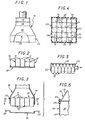
- Such containers 10 are stacked in bunk beds on any pallet, which is not shown in the figures, but which, for example, is assumed therein be generally square in outline.
- FIG. 2 Only such a container bed 10 is shown in FIG. 2, and, by way of example, there is associated therewith, a spacer 12, in the form of a tray, intended to separate it from the underlying bed. .
- This interlayer is sometimes just a flat sheet.
- the containers 10 are arranged side by side, being juxtaposed two by two by their respective faces.
- the necks 11 of the containers 10 are located, in plan, for the bed formed by these containers 10, arranged in a random manner, according to the relative angular orientation of the containers 10.
- the gripping device 15 used for this purpose uses, in a manner known per se, a suction source.
- This fan 16 is disposed at the upper part of a suction hood 18, with intercalation between it and the latter, in the embodiment shown, of a venting device 19 suitably ordered.
- the suction hood 18 is, in the embodiment shown in FIGS. 1 to 4, closed, at its base, by a perforated bottom 20, adapted to form a barrier specific to the mechanical retention of the containers to be grasped against the suction source constituted by the fan 16.
- It may for example be a suitably perforated sheet, a mesh, a network of wires, or any other suitable barrier member.
- the outline of the base of the extractor hood 18, and therefore of its perforated bottom 20, is like that of the container bed 10 to grasp.
- the gripping device 15 comprises a lateral confinement means or skirt 22 by which it is adapted to at least partially cover laterally the entire bed of containers 10 to be gripped.
- Such a skirt 22 is therefore, in this case, rigid.
- the gripping device 15 thus formed is generally mounted movable between two positions, one for sampling, the other for unloading.
- the skirt 22 of this gripping device 15 surrounds the entire container bed 10 to be gripped, as illustrated in FIGS. 3 and 4.
- the sampling device 15 being thus in the sampling position, the input of the suction source constituted by the fan 16 is controlled, and, according to the invention, there is ensured by it a sufficient suction flow. to establish, on either side of the passage section formed by the difference between, on the one hand, the total section of the skirt 22, and, on the other hand, the part of the latter closed by the containers 10 concerned, the depression necessary for training them.
- this passage section is formed by passages 14 and 24, specified above and materialized by hatching in FIG. 4.
- the gripping device 15 is then controlled to move, first vertically, then, optionally, laterally, to its unloading position.
- This training is therefore in particular indifferent to the location of their neck 11 with respect to the perforations in the bottom 20 of the suction hood 18.
- this bottom 20 has in this case only for the simple purpose of ensuring mechanical retention of the containers 10 with respect to the suction of which they are the object.
- the fan 16 constituting the suction source not only drives the containers 10, as described above, but also that of the interlayer 12 underlying them.
- this interlayer 12 is detached from the containers 10 by any suitable means.
- it may be mechanical means, such as fingers 25, coming to be interposed on the path then followed by the interlayer 12, for retaining the latter. Its release can be progressive from its periphery, taking advantage of its flexibility.
- blowing nozzles which, carried by the suction hood 18, are capable of projecting towards the interlayer 12 a jet of fluid capable of ensuring the desired removal for the latter , or, again, suction nozzles coming to apply on the underside of this insert 12.
- the vacuum is removed in particular by at least one of the following operations: stopping the fan 16, bringing the actuating device into action the open air 19, or closing the outlet 17.
- the containers 10 previously gripped by this gripping device 15 are then released by the latter.
- the gripping device admits perforated funds 20 much more openwork than in the prior art.
- any hole which did not end up on the object to be grasped led to leaks and turned out to be harmful: low perforation rates were then used, always less than 50%.
- each hole participates in obtaining the vacuum above the objects to be grasped, and moreover weakens the pressure drop on either side of this bottom.
- High perforation rates are then recommended, which may be around 100%; the bottom can then consist of a mesh.
- connection of the suction opening of the fan constituting the suction source can, as shown diagrammatically by an arrow in this FIG. 5, be made laterally with respect to the volume delimited by the skirt 22 according to the invention and the bottom 20 at the periphery of which it is established.
- This bottom 20 can therefore be full, without any perforation.
- the corresponding gripping device is simplified, the extraction hood, in particular, being eliminated.
- the containers to be seized are bottles, supposed to be of circular section for example.
- skirt 22 according to the invention is rigid, and that it is rigidly attached to the gripping device 15 which it equips.
- such a skirt 22 can at least partly be movable between a sampling configuration for which it is capable of pressing laterally against at least part of those of the objects to be grasped which are on the periphery of the assembly formed by these, and an unloading configuration for which it is separated from said objects.
- each of them may be associated with a spring for this purpose (not shown in the figure).
- their release can be ensured by simple gravity, if, by construction, their support axis 29 is offset laterally relative to the periphery of the assembly formed by the objects to be grasped.
- the walls 27 of the skirt 22 may also be rigid.
- the present invention is moreover not limited to the embodiments and implementation described and shown, but encompasses any variant embodiment and / or combination of their various elements.
- the barrier member 20 for the mechanical retention of the load to be grasped plays a fundamentally different role from the perforated bottoms of similar devices of the prior art. If in both cases it is a mechanical stop of the objects in the direction of the suction source, in the prior art the air flow passage surfaces must be as small as possible to avoid parasitic leaks, whereas according to the invention, on the contrary, it is sought to increase these passage surfaces, tending advantageously towards 100%, while ensuring the stopping of objects.
Landscapes
- Engineering & Computer Science (AREA)
- Mechanical Engineering (AREA)
- Physics & Mathematics (AREA)
- Geometry (AREA)
- Manipulator (AREA)
- Sheets, Magazines, And Separation Thereof (AREA)
- De-Stacking Of Articles (AREA)
Applications Claiming Priority (2)
| Application Number | Priority Date | Filing Date | Title |
|---|---|---|---|
| FR8200290 | 1982-01-11 | ||
| FR8200290A FR2519619B1 (fr) | 1982-01-11 | 1982-01-11 | Procede et dispositif de prehension par aspiration |
Publications (2)
| Publication Number | Publication Date |
|---|---|
| EP0084479A1 true EP0084479A1 (de) | 1983-07-27 |
| EP0084479B1 EP0084479B1 (de) | 1986-03-19 |
Family
ID=9269860
Family Applications (1)
| Application Number | Title | Priority Date | Filing Date |
|---|---|---|---|
| EP83400050A Expired EP0084479B1 (de) | 1982-01-11 | 1983-01-10 | Verfahren und Vorrichtung zum Ergreifen mittels Unterdruck |
Country Status (10)
| Country | Link |
|---|---|
| EP (1) | EP0084479B1 (de) |
| BE (1) | BE895565A (de) |
| DE (1) | DE3362570D1 (de) |
| DK (1) | DK158091C (de) |
| ES (1) | ES518904A0 (de) |
| FR (1) | FR2519619B1 (de) |
| GB (1) | GB2113178A (de) |
| GR (1) | GR77876B (de) |
| IE (1) | IE53864B1 (de) |
| IT (1) | IT1193605B (de) |
Cited By (5)
| Publication number | Priority date | Publication date | Assignee | Title |
|---|---|---|---|---|
| FR2579190A1 (fr) * | 1985-03-21 | 1986-09-26 | Thibault Jacques | Dispositif de levage de charges en couches formees d'objets independants les uns des autres et disposes cote a cote |
| EP0554592A1 (de) * | 1992-02-04 | 1993-08-11 | House Food Industrial Co., Ltd. | Sauggreifer für Roboter |
| EP1162163A1 (de) * | 2000-06-08 | 2001-12-12 | SIG Pack Systems AG | Greifvorrichtung zum Erfassen von Gegenständen und Verfahren zum Betreiben derselben |
| WO2011135031A1 (de) * | 2010-04-28 | 2011-11-03 | Autefa Automation Gmbh | Lagengreifeinrichtung und handhabungseinrichtung |
| CN108573780A (zh) * | 2018-06-19 | 2018-09-25 | 杭州良淋电子科技股份有限公司 | 柔性扁平线缆理线机 |
Families Citing this family (5)
| Publication number | Priority date | Publication date | Assignee | Title |
|---|---|---|---|---|
| GB2157646A (en) * | 1984-04-19 | 1985-10-30 | Secr Defence | A vacuum gripper |
| GB8701347D0 (en) * | 1987-01-22 | 1987-02-25 | Bishop Barn Ltd | Package handling apparatus |
| US4753564A (en) * | 1987-01-23 | 1988-06-28 | Goldco Industries, Inc. | Apparatus and method for effecting movement of selected tiers of stacked articles using pressure differentials |
| DE3824155A1 (de) * | 1988-07-16 | 1990-01-25 | Focke & Co | Vorrichtung zum heben von tray-packungen |
| DE4425003A1 (de) * | 1994-07-15 | 1996-01-18 | Hes Liselotte | Verfahren und Vorrichtung zum Verpacken und Entpacken von Gebinden |
Citations (11)
| Publication number | Priority date | Publication date | Assignee | Title |
|---|---|---|---|---|
| US1579744A (en) * | 1925-06-03 | 1926-04-06 | Francis M Aday | Vacuum lifting device |
| US2390242A (en) * | 1945-03-01 | 1945-12-04 | H M Seippel | Article transferring apparatus |
| DE1075814B (de) * | 1955-07-11 | 1960-02-18 | P Ballantine £x Sons Newark, N J (V St A) | Hohler Saugkopf zum Fordern von Stapelgut |
| US3404787A (en) * | 1966-12-27 | 1968-10-08 | American Chain & Cable Co | Suction lift for article distribution and storage system |
| GB1137031A (en) * | 1965-04-03 | 1968-12-18 | Hebel Gasbetonwerk Gmbh | Method and apparatus for the casting, lifting and setting of plastic mass blocks, inparticular porous concrete blocks |
| DE1930366A1 (de) * | 1968-06-17 | 1969-12-18 | Nat Res Dev | Einrichtung zum Heben von Gegenstaenden mittels Unterdruck |
| DE1926479A1 (de) * | 1969-05-23 | 1970-12-03 | Carlo Schaberger Sondermaschb | Vorrichtung zum Erfassen,Heben und Bewegen von offenen Behaeltnissen,wie Flaschen,Dosen u.ae. |
| FR2166242A1 (de) * | 1972-01-03 | 1973-08-17 | Applic Procedes Electriq | |
| FR2184072A1 (de) * | 1972-05-10 | 1973-12-21 | Laessig Foerdertech Hamburg | |
| FR2316177A1 (fr) * | 1975-07-02 | 1977-01-28 | Marryat Handling Ltd | Palettiseur a tete aspirante |
| GB1483952A (en) * | 1975-10-27 | 1977-08-24 | Smedley Hp Foods Ltd | Load handling |
-
1982
- 1982-01-11 FR FR8200290A patent/FR2519619B1/fr not_active Expired
-
1983
- 1983-01-10 DK DK006783A patent/DK158091C/da active
- 1983-01-10 GR GR70227A patent/GR77876B/el unknown
- 1983-01-10 BE BE0/209866A patent/BE895565A/fr not_active IP Right Cessation
- 1983-01-10 DE DE8383400050T patent/DE3362570D1/de not_active Expired
- 1983-01-10 EP EP83400050A patent/EP0084479B1/de not_active Expired
- 1983-01-11 IE IE53/83A patent/IE53864B1/en not_active IP Right Cessation
- 1983-01-11 GB GB08300586A patent/GB2113178A/en not_active Withdrawn
- 1983-01-11 ES ES518904A patent/ES518904A0/es active Granted
- 1983-01-11 IT IT19059/83A patent/IT1193605B/it active
Patent Citations (11)
| Publication number | Priority date | Publication date | Assignee | Title |
|---|---|---|---|---|
| US1579744A (en) * | 1925-06-03 | 1926-04-06 | Francis M Aday | Vacuum lifting device |
| US2390242A (en) * | 1945-03-01 | 1945-12-04 | H M Seippel | Article transferring apparatus |
| DE1075814B (de) * | 1955-07-11 | 1960-02-18 | P Ballantine £x Sons Newark, N J (V St A) | Hohler Saugkopf zum Fordern von Stapelgut |
| GB1137031A (en) * | 1965-04-03 | 1968-12-18 | Hebel Gasbetonwerk Gmbh | Method and apparatus for the casting, lifting and setting of plastic mass blocks, inparticular porous concrete blocks |
| US3404787A (en) * | 1966-12-27 | 1968-10-08 | American Chain & Cable Co | Suction lift for article distribution and storage system |
| DE1930366A1 (de) * | 1968-06-17 | 1969-12-18 | Nat Res Dev | Einrichtung zum Heben von Gegenstaenden mittels Unterdruck |
| DE1926479A1 (de) * | 1969-05-23 | 1970-12-03 | Carlo Schaberger Sondermaschb | Vorrichtung zum Erfassen,Heben und Bewegen von offenen Behaeltnissen,wie Flaschen,Dosen u.ae. |
| FR2166242A1 (de) * | 1972-01-03 | 1973-08-17 | Applic Procedes Electriq | |
| FR2184072A1 (de) * | 1972-05-10 | 1973-12-21 | Laessig Foerdertech Hamburg | |
| FR2316177A1 (fr) * | 1975-07-02 | 1977-01-28 | Marryat Handling Ltd | Palettiseur a tete aspirante |
| GB1483952A (en) * | 1975-10-27 | 1977-08-24 | Smedley Hp Foods Ltd | Load handling |
Cited By (7)
| Publication number | Priority date | Publication date | Assignee | Title |
|---|---|---|---|---|
| FR2579190A1 (fr) * | 1985-03-21 | 1986-09-26 | Thibault Jacques | Dispositif de levage de charges en couches formees d'objets independants les uns des autres et disposes cote a cote |
| EP0554592A1 (de) * | 1992-02-04 | 1993-08-11 | House Food Industrial Co., Ltd. | Sauggreifer für Roboter |
| US5388879A (en) * | 1992-02-04 | 1995-02-14 | House Food Industrial Co., Ltd. | Suction type robot hand |
| EP1162163A1 (de) * | 2000-06-08 | 2001-12-12 | SIG Pack Systems AG | Greifvorrichtung zum Erfassen von Gegenständen und Verfahren zum Betreiben derselben |
| US6554336B2 (en) | 2000-06-08 | 2003-04-29 | Sig Pack Systems Ag | Method and apparatus for grasping items |
| WO2011135031A1 (de) * | 2010-04-28 | 2011-11-03 | Autefa Automation Gmbh | Lagengreifeinrichtung und handhabungseinrichtung |
| CN108573780A (zh) * | 2018-06-19 | 2018-09-25 | 杭州良淋电子科技股份有限公司 | 柔性扁平线缆理线机 |
Also Published As
| Publication number | Publication date |
|---|---|
| ES8308797A1 (es) | 1983-10-16 |
| GB2113178A (en) | 1983-08-03 |
| IT1193605B (it) | 1988-07-21 |
| EP0084479B1 (de) | 1986-03-19 |
| DK158091C (da) | 1990-09-10 |
| GR77876B (de) | 1984-09-25 |
| DK6783D0 (da) | 1983-01-10 |
| FR2519619B1 (fr) | 1986-02-21 |
| FR2519619A1 (fr) | 1983-07-18 |
| IT8319059A0 (it) | 1983-01-11 |
| DE3362570D1 (en) | 1986-04-24 |
| ES518904A0 (es) | 1983-10-16 |
| IE830053L (en) | 1983-07-11 |
| DK6783A (da) | 1983-07-12 |
| DK158091B (da) | 1990-03-26 |
| BE895565A (fr) | 1983-05-02 |
| GB8300586D0 (en) | 1983-02-09 |
| IE53864B1 (en) | 1989-03-29 |
Similar Documents
| Publication | Publication Date | Title |
|---|---|---|
| EP1095605B1 (de) | Auswurfvorrichtung für Kartusche | |
| EP1127811B1 (de) | Behälter mit vermindertem Geräusch des Deckels während dessen Schliessbewegung | |
| EP0084479A1 (de) | Verfahren und Vorrichtung zum Ergreifen mittels Unterdruck | |
| FR2633265A1 (fr) | Dispositif pour la prehension de pieces souples isolees ou adjacentes, leur manipulation et leur depose, notamment de pieces en cuir et similaires | |
| EP0530426A1 (de) | Greif- und Übertragungszange | |
| FR3048422B1 (fr) | Prehension de palette | |
| FR2676718A1 (fr) | Dispositif pour separer des cliches empiles. | |
| FR2827264A1 (fr) | Dispositif pour separer des objets plats de preference des plaques d'impression | |
| CA2132803C (fr) | Prehenseur d'objets plats et dispositif de depilage equipe de ce prehenseur | |
| FR2579190A1 (fr) | Dispositif de levage de charges en couches formees d'objets independants les uns des autres et disposes cote a cote | |
| CA2132801C (fr) | Dispositif pour separer des prises doubles et dispositif de depilage d'objets plats equipe de ce separateur | |
| EP2456691B1 (de) | Sammelwagen zur entleerung von abfallsammelbehältern | |
| EP0435774B1 (de) | Vorrichtung zum Laden und Entladen einer Speicherkassette mit flachen Gegenständen | |
| FR2831879A1 (fr) | Dispositif d'individualisation de flans en materiau flexible en forme de disque | |
| FR2673612A1 (fr) | Dispositif pour le depilage et la distribution automatique de barquettes. | |
| FR2810961A1 (fr) | Dispositif de distribution automatique de pieces par systeme rotatif incline a empreintes | |
| FR3067336A1 (fr) | Conteneur de collecte de dechets | |
| FR2631924A1 (fr) | Procede automatique de pose de manchon etirable pour l'etiquetage d'emballages plastiques ou metalliques et dispositif de mise en oeuvre de ce procede | |
| EP0295170A1 (de) | Vorrichtung zum Entstapeln von verhältnismässig flachen Gegenständen, wie Briefen oder Postumschlägen | |
| CA2132800C (fr) | Magasin d'approvisionnement en objets plats et dispositif de depilage d'objets plats equipe de ce magasin | |
| FR2478047A1 (fr) | Dispositif pour la manutention d'un materiau sous forme de plaque | |
| EP0633215A1 (de) | Absturzsicherungssystem für eine Schwerlast-Greifvorrichtung | |
| EP0562197B1 (de) | Verfahren und Vorrichtung zum Palettieren von Paketen | |
| EP0704374B1 (de) | Maschine zum Befüllen von Kästen | |
| FR2507948A1 (fr) | Procede et dispositif de decorticage de pieces decoupees dans une plaque |
Legal Events
| Date | Code | Title | Description |
|---|---|---|---|
| PUAI | Public reference made under article 153(3) epc to a published international application that has entered the european phase |
Free format text: ORIGINAL CODE: 0009012 |
|
| AK | Designated contracting states |
Designated state(s): BE DE GB IT LU NL |
|
| RHK1 | Main classification (correction) |
Ipc: B66C 1/02 |
|
| 17P | Request for examination filed |
Effective date: 19830930 |
|
| GRAA | (expected) grant |
Free format text: ORIGINAL CODE: 0009210 |
|
| AK | Designated contracting states |
Kind code of ref document: B1 Designated state(s): BE DE GB IT LU NL |
|
| REF | Corresponds to: |
Ref document number: 3362570 Country of ref document: DE Date of ref document: 19860424 |
|
| ITF | It: translation for a ep patent filed |
Owner name: JACOBACCI & PERANI S.P.A. |
|
| PLBE | No opposition filed within time limit |
Free format text: ORIGINAL CODE: 0009261 |
|
| STAA | Information on the status of an ep patent application or granted ep patent |
Free format text: STATUS: NO OPPOSITION FILED WITHIN TIME LIMIT |
|
| 26N | No opposition filed | ||
| ITTA | It: last paid annual fee | ||
| EPTA | Lu: last paid annual fee | ||
| PGFP | Annual fee paid to national office [announced via postgrant information from national office to epo] |
Ref country code: LU Payment date: 19941201 Year of fee payment: 13 |
|
| PGFP | Annual fee paid to national office [announced via postgrant information from national office to epo] |
Ref country code: DE Payment date: 19941215 Year of fee payment: 13 |
|
| PGFP | Annual fee paid to national office [announced via postgrant information from national office to epo] |
Ref country code: GB Payment date: 19941216 Year of fee payment: 13 |
|
| PGFP | Annual fee paid to national office [announced via postgrant information from national office to epo] |
Ref country code: BE Payment date: 19941222 Year of fee payment: 13 |
|
| PGFP | Annual fee paid to national office [announced via postgrant information from national office to epo] |
Ref country code: NL Payment date: 19950131 Year of fee payment: 13 |
|
| PG25 | Lapsed in a contracting state [announced via postgrant information from national office to epo] |
Ref country code: LU Free format text: LAPSE BECAUSE OF NON-PAYMENT OF DUE FEES Effective date: 19960110 Ref country code: GB Effective date: 19960110 |
|
| PG25 | Lapsed in a contracting state [announced via postgrant information from national office to epo] |
Ref country code: BE Effective date: 19960131 |
|
| BERE | Be: lapsed |
Owner name: CARNAUD EMBALLAGE Effective date: 19960131 |
|
| PG25 | Lapsed in a contracting state [announced via postgrant information from national office to epo] |
Ref country code: NL Effective date: 19960801 |
|
| GBPC | Gb: european patent ceased through non-payment of renewal fee |
Effective date: 19960110 |
|
| NLV4 | Nl: lapsed or anulled due to non-payment of the annual fee |
Effective date: 19960801 |
|
| PG25 | Lapsed in a contracting state [announced via postgrant information from national office to epo] |
Ref country code: DE Effective date: 19961001 |