EP0082718B1 - Ink jet printing head - Google Patents
Ink jet printing head Download PDFInfo
- Publication number
- EP0082718B1 EP0082718B1 EP82306825A EP82306825A EP0082718B1 EP 0082718 B1 EP0082718 B1 EP 0082718B1 EP 82306825 A EP82306825 A EP 82306825A EP 82306825 A EP82306825 A EP 82306825A EP 0082718 B1 EP0082718 B1 EP 0082718B1
- Authority
- EP
- European Patent Office
- Prior art keywords
- ink
- electrode
- container
- nozzle
- head according
- Prior art date
- Legal status (The legal status is an assumption and is not a legal conclusion. Google has not performed a legal analysis and makes no representation as to the accuracy of the status listed.)
- Expired
Links
- 238000007641 inkjet printing Methods 0.000 title claims description 8
- 239000000976 ink Substances 0.000 claims description 55
- 238000007639 printing Methods 0.000 claims description 22
- 239000002245 particle Substances 0.000 claims description 10
- 230000005499 meniscus Effects 0.000 claims description 6
- 230000015572 biosynthetic process Effects 0.000 claims description 4
- 239000000463 material Substances 0.000 claims description 4
- 238000004891 communication Methods 0.000 claims description 3
- 230000006835 compression Effects 0.000 claims description 3
- 238000007906 compression Methods 0.000 claims description 3
- 239000004020 conductor Substances 0.000 claims description 3
- 239000007788 liquid Substances 0.000 claims description 3
- 238000005192 partition Methods 0.000 claims description 3
- 239000003086 colorant Substances 0.000 claims description 2
- 239000011810 insulating material Substances 0.000 claims description 2
- 238000000034 method Methods 0.000 claims description 2
- 239000002184 metal Substances 0.000 description 6
- 230000003628 erosive effect Effects 0.000 description 2
- 238000013019 agitation Methods 0.000 description 1
- PNEYBMLMFCGWSK-UHFFFAOYSA-N aluminium oxide Inorganic materials [O-2].[O-2].[O-2].[Al+3].[Al+3] PNEYBMLMFCGWSK-UHFFFAOYSA-N 0.000 description 1
- 238000010276 construction Methods 0.000 description 1
- 230000008021 deposition Effects 0.000 description 1
- 230000000694 effects Effects 0.000 description 1
- 230000005284 excitation Effects 0.000 description 1
- 239000011521 glass Substances 0.000 description 1
- 239000011159 matrix material Substances 0.000 description 1
- 230000008018 melting Effects 0.000 description 1
- 238000002844 melting Methods 0.000 description 1
- 238000012986 modification Methods 0.000 description 1
- 230000004048 modification Effects 0.000 description 1
- 238000004806 packaging method and process Methods 0.000 description 1
- 230000002093 peripheral effect Effects 0.000 description 1
- 239000004033 plastic Substances 0.000 description 1
- 229920003023 plastic Polymers 0.000 description 1
- 238000007650 screen-printing Methods 0.000 description 1
- 230000011664 signaling Effects 0.000 description 1
- 239000007787 solid Substances 0.000 description 1
- 230000008016 vaporization Effects 0.000 description 1
- 238000009834 vaporization Methods 0.000 description 1
Images

Classifications
-
- B—PERFORMING OPERATIONS; TRANSPORTING
- B41—PRINTING; LINING MACHINES; TYPEWRITERS; STAMPS
- B41J—TYPEWRITERS; SELECTIVE PRINTING MECHANISMS, i.e. MECHANISMS PRINTING OTHERWISE THAN FROM A FORME; CORRECTION OF TYPOGRAPHICAL ERRORS
- B41J2/00—Typewriters or selective printing mechanisms characterised by the printing or marking process for which they are designed
- B41J2/005—Typewriters or selective printing mechanisms characterised by the printing or marking process for which they are designed characterised by bringing liquid or particles selectively into contact with a printing material
- B41J2/01—Ink jet
- B41J2/17—Ink jet characterised by ink handling
- B41J2/175—Ink supply systems ; Circuit parts therefor
- B41J2/17503—Ink cartridges
- B41J2/1752—Mounting within the printer
-
- B—PERFORMING OPERATIONS; TRANSPORTING
- B41—PRINTING; LINING MACHINES; TYPEWRITERS; STAMPS
- B41J—TYPEWRITERS; SELECTIVE PRINTING MECHANISMS, i.e. MECHANISMS PRINTING OTHERWISE THAN FROM A FORME; CORRECTION OF TYPOGRAPHICAL ERRORS
- B41J2/00—Typewriters or selective printing mechanisms characterised by the printing or marking process for which they are designed
- B41J2/005—Typewriters or selective printing mechanisms characterised by the printing or marking process for which they are designed characterised by bringing liquid or particles selectively into contact with a printing material
- B41J2/01—Ink jet
- B41J2/17—Ink jet characterised by ink handling
- B41J2/175—Ink supply systems ; Circuit parts therefor
- B41J2/17503—Ink cartridges
- B41J2/17513—Inner structure
-
- B—PERFORMING OPERATIONS; TRANSPORTING
- B41—PRINTING; LINING MACHINES; TYPEWRITERS; STAMPS
- B41J—TYPEWRITERS; SELECTIVE PRINTING MECHANISMS, i.e. MECHANISMS PRINTING OTHERWISE THAN FROM A FORME; CORRECTION OF TYPOGRAPHICAL ERRORS
- B41J25/00—Actions or mechanisms not otherwise provided for
- B41J25/34—Bodily-changeable print heads or carriages
Definitions
- the present invention relates to ink jet printing heads and to the printers using such heads.
- the invention relates to an ink jet printing head as setforth in the introductory part of claim 1.
- Such a multi-nozzle ink jet printing head is known from US 3750564 wherein the ink is ejected by electro-osmotic action and is contained in a container having a front portion partitioned by vertical walls to define capillary chambers opening into the nozzles. Since in this prior art the electrode is centrally mounted in the ink reservoir, ink needs to be in contact with this electrode and nozzle electrodes, and therefore ink cannot be ejected until the reservoir is empty. Otherwise no electric circuit exists between the central-electrode and the counter-electrodes when the ink level is below the level of the central-electrode.
- FR-A-2 256 034 Also known from FR-A-2 256 034 is an electrostatic multinozzle ink jet head wherein the nozzles are located on the bottom of a reservoir, the top of which is provided with an entry hole whereby the ink can flow into the nozzles till the ink is exhausted.
- This printing head is however unadapted to eject the ink particles in a substantially horizontal direction as it is normally required for the office printing devices.
- EP-0 036 740 is an electro- eroding printing device, wherein a rod of solid ink is inserted into a container and is removably mounted on a transversely movable carriage. This device is unadapted for printing with a liquid ink.
- EP-0 070 110 which forms part of the state of the art for some designated states by virtue of Article 54(3) EPC.
- an ink container directly adjacent to the nozzle plate is connected by means of conduits to a larger-capacity tank which is disposed remote from the printing location.
- the tank In the case of printers in which the head is mounted on a movable carriage, the tank is disposed on the fixed part of the machine and is connected to the container by way of flexible conduits of substantial length. Pump means are required for conveying the ink from the tank to the head, so that the printer is expensive to produce and complicated in operation.
- the object of the present invention is to provide a liquid ink jet printing head in accordance with the introductory part of the claim 1 which is adapted to eject ink particles in a substantially horizontal direction, and which does not require any pump for ejecting the ink till the container is empty.
- the invention is characterised in the manner set forth in claim 1.
- the printer has a platen roller 10 around which a sheet of paper 11 is rolled.
- the roller 10 is capable of rotating selectively to permit it the printing of dots in successive elementary lines, for example for alphabetic printing in a dot-matrix format.
- the printer comprises an ink jet printing head which is mounted on a carriage 13 which is movable transversely in a known per se manner.
- the head 12 essentially comprises a container 14 of insulating material, for the ink 16 which is electrically conducting.
- the container 14 is closed towards the roller 10 by a plate 17 in which a nozzle 18 is provided, for the expulsion of particles of ink 16.
- the ink is in electrical contact with an internal electrode 19 which is connected to the outside of the container 14.
- the printer comprises an electrical control circuit 21 which is operable to supply an electrical voltage pulse between the electrode 19 and a counter-electrode 22 adjacent to the nozzle 18.
- a state of electrical and thermal excitation is then generated between the counter-electrode 22 and the electrode 19, at the location of the meniscus 23 which the ink 16 forms in the nozzle 18, such as to cause a plurality of particles of ink to be expelled by way of the nozzle 18, substantially in the manner described in our European application 82 303 265.1 (publication No. 0 070 110).
- the carriage 13 is of electrically insulating plastics material and is substantially of a cross-like shape, with an internally hollow longitudinal arm 24 (see Figure 2), and a transverse arm 26 of C-shaped cross-section. At the rear, the arm 24 terminates in two limb portions 27 embracing a . first transverse guide 26 for the carriage 13.
- the two ends 29 of the arm 26 are of a bulged configuration and house two rollers 30 which have their axes vertical and which cooperate with a second transverse guide 31 for the carriage 13.
- a metal block 32 of a C-shaped longitudinal section Housed in the hollow portion of the arm 24 (see Fig. 2) is a metal block 32 of a C-shaped longitudinal section. Mounted on the block32 is another roller 33 which however is metal. The roller 33 is urged against the guide 31 by a compression spring 34.
- the carriage 13 is also provided with two resilient arms 35 (see Fig. 3) which are directed upwardly and which are each provided with a projection 36 capable of co-operating with a corresponding seat portion 37 in the side of the container 14 to fit the head 12 vertically on the carriage 13, by a snap-type fitting action.
- the carriage 13 also has two resilient arms 38 which have an arcuate portion 39 and which are capable of engaging a tapered projection portion 40 of the electrode 19. The two resilient arms 38 therefore urge the head 12 towards the roller 10 into a predetermined position as will be seen more clearly hereinafter.
- the two sides of the container 14 each have a knurled portion 41 to make it easier to grip it in the operations of fitting and removing the head 12 to and from the carriage 13.
- a metal plate 42 (see Fig. 2) is fixed to the bottom surface of the longitudinal arm 24 of the carriage 13.
- the metal plate 42 terminates at the front with a tongue portion 43 which contacts the counter-electrode 22 when the head 12 is fitted onto the carriage 13 and determines the above- mentioned longitudinal position thereof.
- the plate 42 terminates with two bent limb portions 44 (see Fig. 3) which bear resiliently against the guide 28.
- a metal tongue portion 46 of bow-like configuration is fitted into a slot or opening 45 (see Fig. 2) in the top wall portion of the arm 24 of the carriage 13.
- the upper end of the portion 46 is in contact with the portion 40 of the electrode 19 when the head 12 is fitted on the carriage 13.
- the two guides 28 and 31 are electrically connected to the control circuit 21. Therefore, on the one hand, by means of the guide 28, the plate 42 and the tongue portion 43, the circuit 21 is electrically connected to the counter-electrode 22 of the head 12, while on the other hand, by way of the guide 31, the roller 33, the block 32, the spring 34, the bow-like portion 46 and the portion 40, the circuit is electrically connected to the electrode 19 of the head 12.
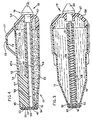
- the container 14 of the head 12 (see Figs. 4 and 5) is oblong in a direction parallel to the nozzle 18 and had a capacity of about 3 cm 3 of ink 16.
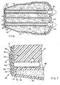
- the container 14 comprises means for permitting the formation of the meniscus 23 (see Fig. 7) in the nozzle 18, until the ink 16 in the container 14 is used up.
- such means comprise a capillary passage between the container 14 and the nozzle 18.
- the container 14 comprises a block 47 (see Fig. 4) which is formed in one piece with the upper wall portion 47A of the container 14.
- the block 47 integrally provides a tube 48 which is open at both ends, with the electrode 19 being disposed therein.
- the block 47 has an end surface 49 which is disposed parallel to the plate 17 at a distance therefrom which is of the same order of magnitude as the thickness of the plate 17, so as to form a space or cavity 50 of capillary depth.
- the thickness of the plate 17 is from 5 to 20 times the diameter of the nozzle 18, which can be from 20 to 100 ⁇ m.
- the diameter of the nozzle 18 is selected as 30 Ilm, the thickness of the plate 17 if 0.6 mm, and the depth of the cavity 50 is about 0.3 mm.
- the capillary passage further comprises a semi- annular cavity 51 which is provided between the outside surface of the end of the tube 48 and the inside surface of an end edge portion 52 of the container 14, which serves to support the plate 17.
- the cavity 51 is also of a capillary thickness and forms a communication between the end of the container 14 and the cavity 50, so that it will be seen that the capillary passage 50 and 51 forms a communication between the end of the container 14 and the nozzle 18, to permit the formation of the meniscus 23, until the ink 6 is used up.
- a layer 54 of spongy material Disposed between the tube 48 (see Fig. 4) and the bottom wall of the container 14 is a layer 54 of spongy material.
- the layer 54 permits the ink to flow more gradually into the cavity 51 when the level of the ink falls below the tube 48. Therefore, the time at which the ink 16 in the head 12 is used up is preceded by a period of reduced ink flow, during which the printing produced is paler, signalling to the operator the need to perform an operation for replacing the head.
- Such an early- warning indication is particularly necessary in situations where the printer is part of an automatic printing apparatus or a peripheral unit of a system for processing or transmitting data, texts or images to be printed.
- the electrode 19 comprises a rod 56 which is housed in the tube 48 and which extends into contact with the plate 17.
- a rear plug portion 57 of the rod 56 forms a sealed closure in the rear wall 58 of the container 14 and terminates in the external tapered projection portion 40.
- the electrode comprises a compression spring 59 (see Fig. 5) which is disposed between the plate 17 and the plug portion 57 which forms the sealed closure at the rear wall 58 of the container.
- a rod 61 of limited length serves as a guide for the spring 59.
- the spring 59 ensures contact along the plate 17 with the ink 16 until the last film thereof, which rises by a capillary action in the passage 50-51.
- Figure 5 shows a plan section of the print head in different planes such as to cross in a first portion the nozzle 18, in a second portion the capillary passage 51, and in a third portion the tube 48.
- the plate 17 which closes the container 14 comprises an alumina plate on which the counter-electrode 22 is formed by a screen printing method.
- the counter-electrode 22 comprises a layer of conducting metal 62 (see Fig. 7), which is about 80 um in thickness and which is further thickened by electrolytic deposition until it is 150 11m thickness in a circular region 63 which is concentric with the nozzle 18, and in a region 64 for contact with the tongue portion 43 (see Fig. 2).
- a layer 66 of high melting point glass, which is 50 11m in thickness, is then formed over the layer 62, to protect the electrode 22 from erosion, while leaving exposed the region 64 for contact with the tongue portion 43.
- the plate 17, together with the two layers 62 and 66, is pierced with a laser beam acting from the side opposite to the layers 62 and 66, to form the nozzle 18 which is about 30 um in diameter, with a predetermined taper towards its orifice.
- the total length of the nozzle 18 is therefore about 0.8 mm, of which an intermediate portion is formed by the thickness of the region 63 of conducting material.
- the counter-electrode 22 Since the meniscus 23 tends to form towards the outside edge of the nozzle 18, the counter-electrode 22 is normally also in contact with the ink 16 and is covered by a thin layer of ink.
- a current is generated in the ink in the nozzle 18, such as to suddenly heat and vaporize a portion of ink 16 which is concentrated towards the smaller-diameter region of the nozzle and is thus adjacent the orifice thereof, limiting the formation of bubbles in the container 14.
- the above-described vaporization effect thus generates a condition of agitation such as to expel the layer at high speed, thus printing a dot on the paper 11 (see Figs. 1 and 2).
- the upper wall 47A (Figs. 1 and 4) of the container 14 is provided with two vent holes 69 which are less than 1 mm in diameter, being for example 0.9 mm in diameter.
- the ink 16 does not escape from the holes 69.
- a bell-shaped portion 71 (Figs. 2 and 4) is disposed over the holes 69 on the wall 47A, within which portion particles of ink can be trapped.
- the bell portion 71 is in turn provided with a hole 72 to ensure that the pressure in the bell portion 71 and thus in the container 14 is ambient pressure.
- the hole 72 could possibly be formed, in any known manner, only when the head 12 is mounted on the carriage 13.
- the bell portion 71 could be formed with a reduced-thickness region 73 which can be pierced with a pin.
- the hole-forming operation could also take place automatically, when the head 12 is removed from it packaging.
- the printing head 112 may be designed for two-colour printing, for example red and black, as is usual in the case of calculating machines and accounting machines.
- Figure 6 shows a plan section of the print head in different planes such as to cross in a first section the nozzles 118, in a second section the capillary passages 151, and in a third section tubes 148.
- the head 112 comprises a double container 114, a portion 115 of which is filled with red ink and another portion 116 is filled with black ink. The two portions 115 and 116 are separated by a partition 100.
- the container comprises a plate 117 with two nozzles 118 and two counter-electrodes 122. Associated with each of the two portions 115 and 116 is a corresponding tube 148 which forms a corresponding capillary passage 150 and 151 and in which a corresponding electrode 119 is housed.
- a two-colour head 112 is provided with a carriage (not shown) which is moved transversely, in dependence on the colour required for the printing operation, by a distance equal to the distance between the two nozzles 118, so that the desired nozzle 118 is selectively moved to the printing location.
- the two nozzles 118 of the head 112 may be disposed in two planes and may be selected by a vertical movement, or they may be convergent by a rotary movement.
Landscapes
- Particle Formation And Scattering Control In Inkjet Printers (AREA)
Applications Claiming Priority (2)
| Application Number | Priority Date | Filing Date | Title |
|---|---|---|---|
| IT68664 | 1981-12-23 | ||
| IT68664/81A IT1145242B (it) | 1981-12-23 | 1981-12-23 | Testina di stampa a getto d inchiostro e relativa stampante seriale |
Publications (3)
| Publication Number | Publication Date |
|---|---|
| EP0082718A2 EP0082718A2 (en) | 1983-06-29 |
| EP0082718A3 EP0082718A3 (en) | 1985-05-08 |
| EP0082718B1 true EP0082718B1 (en) | 1988-12-07 |
Family
ID=11310223
Family Applications (1)
| Application Number | Title | Priority Date | Filing Date |
|---|---|---|---|
| EP82306825A Expired EP0082718B1 (en) | 1981-12-23 | 1982-12-21 | Ink jet printing head |
Country Status (5)
| Country | Link |
|---|---|
| US (1) | US4503442A (it) |
| EP (1) | EP0082718B1 (it) |
| JP (1) | JPS58147378A (it) |
| ES (1) | ES8401382A1 (it) |
| IT (1) | IT1145242B (it) |
Families Citing this family (25)
| Publication number | Priority date | Publication date | Assignee | Title |
|---|---|---|---|---|
| JPS59156770A (ja) * | 1983-02-25 | 1984-09-06 | Canon Inc | インパクト型プリンタ |
| IT1159032B (it) * | 1983-06-10 | 1987-02-25 | Olivetti & Co Spa | Testina di stampa a getto selettivo d inchiostro |
| IT1162919B (it) * | 1983-07-20 | 1987-04-01 | Olivetti & Co Spa | Dispositivo di scirttura a getto di inchiostro particolarmente per stampanti ad alta velocita |
| IT1160247B (it) * | 1983-12-27 | 1987-03-04 | Olivetti & Co Spa | Testina di stampa seriale a getto d'inchiostro elettricamente conduttivo |
| IT1179973B (it) * | 1984-02-15 | 1987-09-23 | Olivetti & Co Spa | Testina di stampa a getto selettivo di inchiostro e cartuccia di inchiostro per tale testina |
| US4785314A (en) * | 1984-03-14 | 1988-11-15 | Canon Kabushiki Kaisha | Internally pressure-regulated ink supply |
| EP0605388B1 (en) * | 1984-05-22 | 2001-03-14 | Seiko Epson Corporation | Ink tank |
| JPS6135955A (ja) * | 1984-07-30 | 1986-02-20 | Canon Inc | 液体噴射記録ヘツド |
| IT1179109B (it) * | 1984-09-10 | 1987-09-16 | Olivetti & Co Spa | Testina di stampa seriale a getto d'inchiostro |
| US4591875A (en) * | 1985-04-12 | 1986-05-27 | Eastman Kodak Company | Ink cartridge and cooperative continuous ink jet printing apparatus |
| US4739347A (en) * | 1985-07-17 | 1988-04-19 | Ricoh Company, Ltd. | Ink supply system for use in an ink-jet printer |
| IT1182682B (it) * | 1985-11-14 | 1987-10-05 | Olivetti & Co Spa | Testina di stampa a getto d'inchiostro elettricamente conduttivo e relativo dispositivo di stampa |
| IT1195146B (it) * | 1986-09-01 | 1988-10-12 | Olivetti & Co Spa | Inchiostro particolarmente adatto per una stampante a getto d inchiostro |
| IT1195151B (it) * | 1986-09-05 | 1988-10-12 | Olivetti & Co Spa | Apparecchiatura per ripristinare il funzionamento degli ugelli di una testina di stampa a getto d inchiostro e relativo procedimento |
| US4809015A (en) * | 1988-03-14 | 1989-02-28 | Eastman Kodak Company | Continuous ink jet printer having modular print head assembly |
| AU645492B2 (en) * | 1989-05-01 | 1994-01-20 | Canon Kabushiki Kaisha | Container for ink jet head cartridge |
| US5934475A (en) * | 1989-05-01 | 1999-08-10 | Canon Kabushiki Kaisha | Container for accommodating ink jet head cartridge |
| DE59006328D1 (de) * | 1989-10-03 | 1994-08-04 | Siemens Ag | Druckmodul für eine tintendruckeinrichtung mit einem tintenvorratsbehälter mit integriertem tintendruckkopf. |
| JPH04214362A (ja) * | 1990-12-10 | 1992-08-05 | Canon Inc | インクジェット記録装置,インクタンク,および記録ヘッドとインクタンクとを一体としたヘッドカートリッジ |
| US6332675B1 (en) | 1992-07-24 | 2001-12-25 | Canon Kabushiki Kaisha | Ink container, ink and ink jet recording apparatus using ink container |
| US6467890B1 (en) | 1993-06-29 | 2002-10-22 | Canon Kabushiki Kaisha | Partitioned ink tank |
| US6206514B1 (en) | 1993-06-29 | 2001-03-27 | Canon Kabushiki Kaisha | Ink tank unit, an ink jet cartridge having said ink tank unit and an ink jet apparatus having said ink jet cartridge |
| ATE226516T1 (de) * | 1993-06-29 | 2002-11-15 | Canon Kk | Behälter für flüssigkeit, tintenstrahlkassette mit diesem behälter für flüssigkeit und tintenstrahlapparat mit dieser tintenstrahlkassette |
| JP3324719B2 (ja) * | 1995-03-22 | 2002-09-17 | セイコーエプソン株式会社 | インクジェットプリンタ |
| KR100790903B1 (ko) * | 2007-01-23 | 2008-01-03 | 삼성전자주식회사 | 전기전하집중과 액기둥 잘림을 이용한 액적 토출 장치 및그 방법 |
Family Cites Families (16)
| Publication number | Priority date | Publication date | Assignee | Title |
|---|---|---|---|---|
| SE349676B (it) * | 1971-01-11 | 1972-10-02 | N Stemme | |
| DE2455019A1 (de) * | 1973-12-28 | 1975-07-10 | Xerox Corp | Schreibvorrichtung |
| SE371900B (it) * | 1973-12-28 | 1974-12-02 | Facit Ab | |
| JPS5416739B2 (it) * | 1974-12-25 | 1979-06-25 | ||
| IT1129356B (it) * | 1980-10-31 | 1986-06-04 | Olivetti Ing C Spa | Dispositivo di stampa a getto selettivo di inchiostro |
| DE2543451C2 (de) * | 1975-09-29 | 1982-05-06 | Siemens AG, 1000 Berlin und 8000 München | Piezoelektrisch betriebener Schreibkopf für Tintenmosaikschreibeinrichtungen |
| US4074284A (en) * | 1976-06-07 | 1978-02-14 | Silonics, Inc. | Ink supply system and print head |
| JPS5419816A (en) * | 1977-07-12 | 1979-02-14 | Ricoh Kk | Printer |
| JPS5483433A (en) * | 1977-12-15 | 1979-07-03 | Ricoh Co Ltd | Liquid level detecting and controlling device in color ink jet recorder |
| JPS5542874A (en) * | 1978-09-21 | 1980-03-26 | Canon Inc | Recording head cartridge |
| JPS5581170A (en) * | 1978-12-14 | 1980-06-18 | Ricoh Co Ltd | Ink injector |
| JPS56117682A (en) * | 1980-02-22 | 1981-09-16 | Canon Inc | Recording device |
| JPS55150372A (en) * | 1979-05-11 | 1980-11-22 | Seiko Epson Corp | Printer |
| JPS5640565A (en) * | 1979-09-12 | 1981-04-16 | Canon Inc | Liquid injection recording device |
| EP0086547B1 (en) * | 1980-03-20 | 1986-01-02 | Ing. C. Olivetti & C., S.p.A. | Ink container for dot matrix printer |
| US4329698A (en) * | 1980-12-19 | 1982-05-11 | International Business Machines Corporation | Disposable cartridge for ink drop printer |
-
1981
- 1981-12-23 IT IT68664/81A patent/IT1145242B/it active
-
1982
- 1982-12-21 EP EP82306825A patent/EP0082718B1/en not_active Expired
- 1982-12-23 US US06/452,845 patent/US4503442A/en not_active Expired - Fee Related
- 1982-12-23 JP JP57235169A patent/JPS58147378A/ja active Pending
- 1982-12-23 ES ES518641A patent/ES8401382A1/es not_active Expired
Also Published As
| Publication number | Publication date |
|---|---|
| US4503442A (en) | 1985-03-05 |
| ES518641A0 (es) | 1983-12-16 |
| IT1145242B (it) | 1986-11-05 |
| ES8401382A1 (es) | 1983-12-16 |
| EP0082718A3 (en) | 1985-05-08 |
| IT8168664A0 (it) | 1981-12-23 |
| EP0082718A2 (en) | 1983-06-29 |
| JPS58147378A (ja) | 1983-09-02 |
Similar Documents
| Publication | Publication Date | Title |
|---|---|---|
| EP0082718B1 (en) | Ink jet printing head | |
| EP0133167B1 (en) | Ink jet printer, particularly for high speed printing | |
| EP0408241B1 (en) | Print head for a thermal ink jet printer | |
| US5663754A (en) | Method and apparatus for refilling ink jet cartridges | |
| US4968998A (en) | Refillable ink jet print system | |
| EP0100624B1 (en) | Ink jet printer with bubble driven flexible membrane | |
| US4571599A (en) | Ink cartridge for an ink jet printer | |
| US4703332A (en) | Ink jet print head and printer | |
| NL1001205C2 (nl) | Inkttankpatroon voor een registratie-apparaat van het inktjet-type. | |
| US4432003A (en) | Ink-jet printing device | |
| KR0174704B1 (ko) | 잉크-젯 프린터의 칼라-잉크 재충전 장치 | |
| US5801735A (en) | Automated system for refilling ink jet cartridges | |
| US4503443A (en) | Serial ink jet printing head | |
| EP0960736A1 (en) | Ink jet printing device and an ink cartridge | |
| KR960040664A (ko) | 잉크제트 프린터/플롯터 | |
| US4628334A (en) | Ink jet print head cartridge assembly | |
| IT8367641A1 (it) | Testina di stampa a getto selettivo d'inchiostro | |
| JPH068456A (ja) | コーティング付与装置 | |
| EP0128679B1 (en) | Ink jet print head | |
| EP0709205B1 (en) | Method and apparatus for refilling a print cartridge | |
| EP0147186B1 (en) | Serial printing head of electrically conductive ink jet type | |
| JP3075286B2 (ja) | インクジェット記録装置 | |
| JP2004322659A (ja) | インクジェット記録装置、及びインクカートリッジ | |
| JPH11320907A (ja) | インク供給容器 | |
| JP2841662B2 (ja) | インクジェット記録装置用のインクタンク |
Legal Events
| Date | Code | Title | Description |
|---|---|---|---|
| PUAI | Public reference made under article 153(3) epc to a published international application that has entered the european phase |
Free format text: ORIGINAL CODE: 0009012 |
|
| AK | Designated contracting states |
Designated state(s): CH DE FR GB LI |
|
| PUAL | Search report despatched |
Free format text: ORIGINAL CODE: 0009013 |
|
| AK | Designated contracting states |
Designated state(s): CH DE FR GB LI |
|
| 17P | Request for examination filed |
Effective date: 19851022 |
|
| 17Q | First examination report despatched |
Effective date: 19861022 |
|
| R17C | First examination report despatched (corrected) |
Effective date: 19870427 |
|
| GRAA | (expected) grant |
Free format text: ORIGINAL CODE: 0009210 |
|
| AK | Designated contracting states |
Kind code of ref document: B1 Designated state(s): CH DE FR GB LI |
|
| PG25 | Lapsed in a contracting state [announced via postgrant information from national office to epo] |
Ref country code: LI Effective date: 19881207 Ref country code: CH Effective date: 19881207 |
|
| REF | Corresponds to: |
Ref document number: 3279267 Country of ref document: DE Date of ref document: 19890112 |
|
| ET | Fr: translation filed | ||
| REG | Reference to a national code |
Ref country code: CH Ref legal event code: PL |
|
| PLBE | No opposition filed within time limit |
Free format text: ORIGINAL CODE: 0009261 |
|
| STAA | Information on the status of an ep patent application or granted ep patent |
Free format text: STATUS: NO OPPOSITION FILED WITHIN TIME LIMIT |
|
| 26N | No opposition filed | ||
| PGFP | Annual fee paid to national office [announced via postgrant information from national office to epo] |
Ref country code: FR Payment date: 19911209 Year of fee payment: 10 |
|
| PGFP | Annual fee paid to national office [announced via postgrant information from national office to epo] |
Ref country code: GB Payment date: 19911210 Year of fee payment: 10 |
|
| PGFP | Annual fee paid to national office [announced via postgrant information from national office to epo] |
Ref country code: DE Payment date: 19920131 Year of fee payment: 10 |
|
| PG25 | Lapsed in a contracting state [announced via postgrant information from national office to epo] |
Ref country code: GB Effective date: 19921221 |
|
| GBPC | Gb: european patent ceased through non-payment of renewal fee |
Effective date: 19921221 |
|
| PG25 | Lapsed in a contracting state [announced via postgrant information from national office to epo] |
Ref country code: FR Effective date: 19930831 |
|
| PG25 | Lapsed in a contracting state [announced via postgrant information from national office to epo] |
Ref country code: DE Effective date: 19930901 |
|
| REG | Reference to a national code |
Ref country code: FR Ref legal event code: ST |