EP0081682A2 - Interrupteur électrique à curseur - Google Patents
Interrupteur électrique à curseur Download PDFInfo
- Publication number
- EP0081682A2 EP0081682A2 EP82110371A EP82110371A EP0081682A2 EP 0081682 A2 EP0081682 A2 EP 0081682A2 EP 82110371 A EP82110371 A EP 82110371A EP 82110371 A EP82110371 A EP 82110371A EP 0081682 A2 EP0081682 A2 EP 0081682A2
- Authority
- EP
- European Patent Office
- Prior art keywords
- contact
- slide
- housing
- lever
- switch
- Prior art date
- Legal status (The legal status is an assumption and is not a legal conclusion. Google has not performed a legal analysis and makes no representation as to the accuracy of the status listed.)
- Granted
Links
Images


Classifications
-
- H—ELECTRICITY
- H01—ELECTRIC ELEMENTS
- H01H—ELECTRIC SWITCHES; RELAYS; SELECTORS; EMERGENCY PROTECTIVE DEVICES
- H01H13/00—Switches having rectilinearly-movable operating part or parts adapted for pushing or pulling in one direction only, e.g. push-button switch
- H01H13/50—Switches having rectilinearly-movable operating part or parts adapted for pushing or pulling in one direction only, e.g. push-button switch having a single operating member
- H01H13/56—Switches having rectilinearly-movable operating part or parts adapted for pushing or pulling in one direction only, e.g. push-button switch having a single operating member the contact returning to its original state upon the next application of operating force
- H01H13/562—Switches having rectilinearly-movable operating part or parts adapted for pushing or pulling in one direction only, e.g. push-button switch having a single operating member the contact returning to its original state upon the next application of operating force making use of a heart shaped cam
-
- H—ELECTRICITY
- H01—ELECTRIC ELEMENTS
- H01H—ELECTRIC SWITCHES; RELAYS; SELECTORS; EMERGENCY PROTECTIVE DEVICES
- H01H3/00—Mechanisms for operating contacts
- H01H3/001—Means for preventing or breaking contact-welding
Definitions
- the invention relates to an electrical slide switch having at least one contact rocker which can be pivoted by means of a slide and a spring mechanism and which is in contact with a contact at least in its pivoting end position.
- Such switches with snap mechanism are generally known and are preferably used for switching on and off such electrical devices in which high current peaks occur when switching on, e.g. with color television sets.
- the spring mechanism ensures that the contact rocker moves quickly as soon as the slide has passed a "dead center".
- the object of the invention is to improve the electrical slide switch of the type mentioned in such a way that the normal switching function is maintained even with welded contacts.
- This object is achieved according to the invention by a separating mechanism which forcibly (mechanically) separates the contact rocker from its associated contact when the switch is opened.
- a weld between the contact rocker and its associated contact is therefore torn open, so that the spring mechanism is then able to move the switching rocker into the open position of the switch.
- a certain amount of damage to the surface of the contacts touching one another can be tolerated without the function of the switch being noticeably influenced in subsequent switching operations.
- the separating mechanism is designed as a pivotable insulating material lever which can be pivoted via the slide, the contact rocker being pivoted so that it moves in the direction of a separation of the contact rocker and its associated contact when the slide moves in the direction of opening the switch works.
- the arrangement of the isolating lever and the contact rocker is preferably selected such that the isolating lever only acts on the contact rocker shortly before the slide reaches the end position.
- the insulating material lever is resiliently biased in a direction in which it is out of engagement with the shift rocker. This makes it easier to operate the insulating material lever, since it only has to be done in one direction.
- the insulating lever is mounted on a housing closing plate, a nose projecting into the pivoting area of the contact rocker can be brought into contact with the contact rocker and a pin protruding from the slide pushes against a stop surface of the insulating lever when the slide moves and panned this.
- the distance between the stop surface and the nose of the slide thus ensures very simply that the insulating lever only acts on the contact rocker shortly before the slide reaches the end position.
- the spring action of the insulating material lever is achieved in a particularly simple manner in that the insulating material lever has an integrally connected spring arm which is supported against a supporting surface of the housing closing plate.
- a particularly simple mounting of the insulating material lever is obtained by holding it in a recess of the housing closing plate on a pivot bearing designed as a bolt, only the nose protruding from the recess.
- a pivot bearing designed as a bolt it is expedient to design the end of the bolt as a caulking pin, as a result of which the insulating material lever can be easily, securely and permanently attached to the housing closing plate.
- each contact rocker is assigned its own insulating material lever.
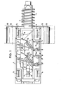
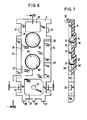
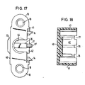
- Fig. 1 shows an embodiment of a two-pole slide switch, in which the invention is used.
- the housing is open here, whereby the separating mechanism cannot be seen.
- a slide 2 In a housing 1, a slide 2 is guided in a straight line and protrudes with one end out of the housing.
- Two contact rockers 3, 3 ' (see FIGS. 34 and 35) are arranged essentially transversely to its longitudinal extent within the housing, each of which is pivotably mounted in a support eyelet 4,4 1 (see FIGS. 36 and 37).
- the support eyelets 4 and 4 ' are laterally attached to the housing 1 in corresponding recesses.
- the contact rockers 3 and 3 ' are pressed into their swivel limit positions via spiral springs 5 and 5'.
- the coil springs are here with one end on a projection 150 (FIG. 34) of the contact rocker and with its other end on a projection 15 or. 15 'supported on the slide.
- the switch is open, ie contact surfaces 20 and 20 'of the rocker arms 3 and 3' are removed from contact surfaces 21 and 21 'of associated contact eyes 6 and 6'.
- These contact eyelets 6 and 6 ' are also fastened in suitable recesses on the housing 1 and lie on the side of the housing opposite the support eyelets 4. If the slide is moved to the left in FIG. 1, the springs 5 are thereby tensioned and at the same time are moved to the left with their end facing away from the switching rockers. The end of the springs facing the contact rockers initially remains stationary. As soon as the projections 15 and thus the ends of the springs facing away from the contact rockers have been moved beyond a certain point, the springs push the contact rockers in FIG. 1 to the right, so that the contact rockers with their contact surface in the direction of the contact eyelets 6 and 6 '"snap". In this case, the contact surfaces 20 and 20 'come into contact with the contact surfaces 21 and 21'.
- the slide is then held in the switched-on position of the switch via a latching mechanism 10 (FIG. 2).
- a latching mechanism 10 FIG. 2
- the slide is first pushed a little further to the left in Fig. 1, whereby the locking mechanism disengages again, whereupon the slide under the action of the spring 7, which is supported on the one hand on the housing 1 and on the other hand on the slide 1 on the right, whereby the switching process takes place in an analogous manner.
- Lateral fastening arms 18 are provided on the housing, each of which has a screw opening 19.
- the housing has outstanding locking catches 14, which are used to fasten a housing locking plate 8 (FIG. 2).
- a support 16 projecting from the bottom of the housing, from which a pin 17 protrudes, by means of which the housing closing plate can be centered and fastened.
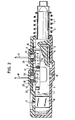
- FIG. 2 In the sectional view of FIG. 2 additional details of the housing closing plate 8 as well as the separating mechanism and the snap mechanism can be seen.
- the separating mechanism contains, as an essential element, an "insulating material lever" 9, which is pivotably mounted on a bolt 13 of the housing closing plate 8.
- a nose 12 of the insulating material lever 9 projects into the pivoting range of the switching rocker 3.
- the pin 11 projecting upward from the slide 2 abuts against a stop surface of the insulating material lever and pivots it, as a result of which the lug 12 comes into contact with the switching rocker 3 and pushes it out of its closed position.
- Fig. 2 the switch is shown in the open position, in which the rocker arm 3 is located away from the nose 12.
- the insulating lever 9 is accommodated in a recess 25 of the housing closing plate 8, only the nose 12 protruding beyond the silhouette of the housing closing plate 8.
- the insulating lever 9 is shown partially cut off, so that the pin 11 is more visible.
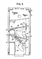
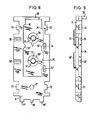
- the mode of operation of the separating mechanism can be better seen from FIGS. 3 to 5.
- Fig. 3 shows a plan view of the inside of the housing closing plate with inserted insulating levers. The are in a recess 28 of the housing closing plate Insulating lever 9 or 9 'mounted on bolts 13 or 13'. The rest position of the insulating material lever is shown here in solid lines, while its position deflected by the pins 11 and 11 'is shown in broken lines.
- locking lugs 23 can be seen, into which the locking catches 14 of the housing can snap.
- insulating lever 9 or 9 ' are integrally formed with a spring arm 22 or 22', which spring arms are supported on support surfaces of the side wall of the recess 25.
- the lugs 12 and 12 'of the insulating material levers 9 and 9' protrude upward from the plane of the drawing in FIG. 3. Furthermore, the pins 11 and 11 'can be seen in their two limit positions, the position of the pins in the switched-on position being characterized in that their reference numerals are placed in brackets. From this it can then be seen that the pins 11 or 11 'in their one limit position press against a nose of the insulating lever and pivot it against the force of the spring arm 22 or 22', the insulating lever then assuming the position shown in broken lines and in front all the nose 12 or 12 'is also pivoted.
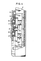
- FIG. 4 shows a schematic sectional view, in which - in contrast to FIG. 2 - one of the insulating lever 9 is shown in full, while the other insulating lever 9 'is partially broken open to denote the position of the pin 11'Epnauer.
- Fig. 5 shows a schematic plan view of the switch with the position of the insulating lever 9 or 9 '.
- the contact rocker 3 is already opened by the spring 5, d. H. removed from the contact eyelet 6, while the contact rocker 3 'is still in contact with the contact eyelet 6'.
- the nose 12 'of the insulating material lever 9' would have already pushed the contact rocker 3 'away.
- 5 is essentially used to show the extent to which the nose of the insulating material lever moves the contact rocker.
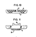
- the housing closing plate 8 has essentially a rectangular base area which is interrupted by a few projections or recesses. These projections or recesses serve on the one hand as grids with the housing and on the other hand as openings or guides for the contact or support eyes.
- the housing closing plate has circular projections 30 and 30 'on the outside thereof, corresponding recesses 28 and 28' being provided on the inside, in which the bolts 13 are centered or 13 'are attached.
- the insulating material levers are pivotably mounted on these bolts, and they are additionally guided on the side walls of the recess 28.
- the bolts 13 and 13 ' have caulking pins 31 and 31' on their end projecting into the interior of the switch, which can be permanently deformed and hold the insulating material levers, e.g. 2 and 4 can be seen.
- the housing closing plate 8 has on its side facing the housing a recess 25 which is essentially rectangular.
- the essential part of the insulating material levers 9 and 9 ' is located within this recess 25, lateral projections 35, 36 and 35', 36 'serving as support surfaces for the insulating material levers.
- the projections 36 and 36 ' serve as support surfaces for the spring arms 22 and 22', while the projections 35 and 35 'serve as end stops for the arms 172 (FIG. 38) of the insulating material levers. 8, these projections are formed on the side walls of the recess 25.
- the housing closing plate on its side facing the housing has a guide 38 at one end (cf. FIG. 11), which is adapted to the shape of the slide.
- the opening 27 for the pin 17 can be seen particularly clearly in FIG. 10.
- a recess 37 can also be seen, into which the carrier 16 of the housing projects.
- the housing 1 has an essentially cuboid shape and is formed by a base 40, two side walls 41 and a front and rear end wall 42 and 43, respectively. It is open at the top and is closed by the housing closing plate 8.
- the two fastening arms 18 protrude laterally on the side walls 41 in the region of one end of the housing.
- On the side walls 41 and / or the floor 40 several projections or elevations are attached, which serve to guide the slide, to hold the support and contact eyelets or to support and fasten the housing closing plate.
- a recess for the latching mechanism 10 is embedded in the bottom 40 of the housing 1, which is explained in more detail in connection with FIG. 24.
- the side guide for the slide is indicated.
- the wall 43 has a recess 44aif which is adapted to the shape of the slide.
- the individual guides 45, 46, 49, 62, 70, 69 are each protruding from the housing base 40 and are raised by webs connected to the adjacent side wall 41 with smooth surfaces on their side facing the housing center.
- the guide surfaces 45, 46, 69 and 70 in the area of the four corners of the housing enclose the locking catches 14 and protrude from the housing base 40 up to almost the height of the side walls 41. They only end so far below the upper edge of the side walls that the housing closing plate used is flush with the housing side wall. The same also applies to the middle guide surfaces 49 and 62, respectively.
- the walls of the webs of the guide surfaces pointing forward or backward have recesses 54, 55 which serve to receive the contact eyelets 6. It can be seen that further contact eyelets can be inserted into further recesses provided without reference symbols.
- the side wall 41 is connected to the housing base 40 via short stiffening ribs 63, 64, 65, 66.
- the webs of the guide surfaces are provided with stops 56, 57, 58, 59, on which the contact rockers come to a stop in their respective limit positions.
- recesses 51 and 52 are also provided on webs, in which the support eyelets 4 are held.
- the contact rocker arms are in turn pivotably attached to these support eyes, the edges of the guide surfaces 46, 62 and 69 being rounded off in the region of the recesses 51 and 52, respectively, in order to ensure a sufficient pivoting range of the contact rockers.
- the recesses 51 and 52 are T-shaped, and they extend as far as the side wall 41 so as to enable the end of the contact rockers which projects toward the side wall to pivot freely.
- the guide surfaces 46, 62 and 69 protrude only slightly beyond the bottom 40 of the housing, while the webs 48, 50, 53 leading to them extend to just below the edge the side wall 41 protrude upwards.
- 67 and 68 are rectangular openings in the floor 40, which are located between the respective side wall 41 and the locking catches 14.
- FIG. 13 The sectional view of FIG. 13 reveals that the housing base 40 has a projection 73, in the interior of which there is a recess 71 for the latching mechanism. A projection 100 projecting inwards towards the housing can also be seen, which has the configuration shown in more detail in FIG. 24. Furthermore, FIG. 13 shows better the individual webs 48, 50, 53 and the recesses 51 and 52. 74 shows a further recess provided on the end wall 42 for possible further contacts. Furthermore, Fig. 13 clearly shows that the vertical leg of the T-shaped recess 51 extends to the side wall 41. It can also be seen that the guide surfaces 46, 62 and 69 protrude only slightly beyond the bottom 40 of the housing.
- FIG. 14 The view of FIG. 14 on the underside of the housing shows the relative position of the recesses 51, 52, 54, 55 that hold the individual eyelets. Recesses 75 and 76 can also be seen, into which the further eyelets mentioned above can be inserted, so that, for example, a changeover switch can be created.
- FIG. 14 shows the fastening arms 18 with screw or fastening openings 19 more clearly.
- 15 and 16 illustrate the position of the recess 44 through which the slide can emerge from the end wall 43 of the housing.
- the length of the locking catches 14 can also be seen better, from which it can be seen in particular that the locking catches protrude somewhat from the housing.
- the arrangement of the carrier 16 and the pin 17 can be seen more clearly from FIG.
- the pin 17 carries at its upper end a caulking pin 17 'which projects through the opening 27 of the housing lock plate and with which the housing lock plate can be firmly connected to the housing.
- FIG. 18 shows several recesses 77, 78 and 79 in the housing end wall 42, into which the individual projections 77% 78 'and 79' (FIG. 8) of the housing closing plate 8 engage, as a result of which the latter is centered relative to the housing.
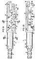
- this slide consists of three sections, one of which is always inside the housing, while the second passes through the end wall of the housing.
- the third section is always outside the housing and is used to hold a push button.
- the latter third section 81 has a cylindrical or rectangular or square cross section and, in the exemplary embodiment shown, has two circumferential grooves which are used to fasten a pushbutton (not shown).
- the second section passing through the end wall of the housing is referred to here as plunger 82. It can also have a cylindrical or rectangular cross section. At its end located at the del housing, it has a circumferential groove 91, which serves to fasten the spring 7 (FIG. 1). At its other end, the plunger opens into the first section, the cross section of this first section being somewhat larger than that of the plunger 82, so that there is a wall 90 on which the spring 7 can be supported during assembly. At When the switch is fully assembled, this wall 90 is also located within the housing and thus serves as a stop which limits the path of the slide when it hits the wall 42 (FIG. 12) of the housing.
- the first section located within the housing essentially consists of a rectangular plate 83, of which protrusions protrude in one piece. At its end facing away from the plunger 82, this plate 83 has a recess 86 with elevations 85 and 89 protruding vertically upwards, the width of the recess 86 being adapted to the width of the carrier 16 of the housing, so that the slide through the recess 86 is guided on the carrier 16.
- the elevation 84 protrudes vertically essentially over the entire length of the plate 83. From this elevation 84 again protrude perpendicularly to it, i. H. parallel to the plate 83 ribs 80 and 80 'in front, on which the support lugs 15 and 15' for the springs 5 and 5 'are supported.
- the edge of the elevation 84 facing away from the plate 83 ends below the profile of the wall 90.
- Two elevations 87 and 88 protrude laterally outwards from the elevation 84, to which the pins 11 and 11 'are fastened.
- the transition between the elevation 84 and the wall 90 takes place in two stages, as is shown by the visible edges 92 'and 90' (see FIGS. 19 and 20).
- a further elevation 89 is provided on the elevation 84 in the region of the recess 86, which protrudes up to the full height of the cross section of the wall 90.
- the features of the slide which are important for the invention lie in the spatial relationship between the support lugs 15 and 15 'and the pins 11 and 11', as a result of which the desired interaction between the spring mechanism and the separating mechanism and in particular the desired engagement of the pins 11 with the assigned stop surfaces of the insulating material lever is ensured.
- a recess 95 is provided on the underside of the plate 83, which generally expresses a V-shaped shape and is thus delimited by side walls 97 and 98.
- an opening 96 is provided which receives a leg 181 of a locking wire (FIGS. 40 and 41).
- the long leg 180 of the locking wire is guided in the recess 95 on the plate 83, its pivoting range being limited by the side walls 97 and 98.
- An "island" 100 is located within the recess 99 (FIG. 21) or 106 (FIG. 24).
- Two Side walls 101 and 102 of this island 100 run at an acute angle to one another and are connected to one another by a rounding.
- a nose protrudes approximately vertically from the side wall 102, which is also delimited by a curve 105 which describes an arc of approximately 180 °.
- the island 100 runs with a side wall 104 essentially parallel to the longitudinal direction of the slide or the housing and merges at an obtuse angle into a side wall 103, which then merges into the side wall 101 at an angle of somewhat less than 90 °.
- a side wall 107 runs approximately parallel to the longitudinal direction of the slide or the housing. This wall is at an obtuse angle of about 135 0 via a rounding in a side wall 108, the rounding verbinderden about which the side walls 101 and 102 is gengenüber. Opposite the side wall 102, the side wall 108 then merges into a side wall 109, which is approximately transverse to the longitudinal direction of the slide or the housing. From there emerges a nose 110, which projects toward the side wall 102. This nose 110- then merges via an inclined side wall 111, which is approximately opposite the nose 105, into a short side wall 112, which in turn is transverse to the longitudinal direction of the slide or the housing.
- a side wall 113 runs parallel to the side wall 107 and thus opposite and parallel to the side wall 104.
- This side wall then merges into a section 114, which in turn runs approximately parallel to the side wall 103.
- a side wall 115 then adjoins at an obtuse angle of approximately 160 to 170 °, which merges into a short section * approximately at the level of the nose connecting the side walls 101 and 102 and runs parallel to the side wall 107.
- the side walls 116 and 107 are connected to one another via a transverse wall 117.
- the leg 182 of the locking wire bears against the wall 117. If the slide is moved, this leg 182 is also moved and guided between the walls 107 and 101 until it abuts the nose 110 via the walls 108 and 109. The slide is then in its other limit position. With a slight backward displacement of the slide, the leg 182 then abuts the wall 102, where it is guided up to the nose 105. In this position, the slide and thus the switch is in its one stationary position, specifically in the illustrated embodiment with the arrangement of the contacts according to FIG. 1 in its switched-on position. When the switch is actuated again, the leg slides along the nose 105 to the wall 111 and is guided there to the wall 112. The slide is then again in its foremost limit position. When released, the leg is then guided between the walls 113 and 104 or 114 and 103 and then slides along the wall 115 to the transverse wall 117, where the switch is in its other limit position, which in the exemplary embodiment shown is its switched-off position.
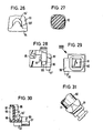
- 26 to 31 show different sections or details of the slide. 26 shows the more precise configuration of the rib 80 and the support lug 15.
- the support lug 15 here essentially has the shape of a spherical cap and, of course, lies above the plate 83, so that the springs 5 and 5 'are supported all around.
- FIG. 27 shows the cross section of the plunger 82
- FIG. 29 shows a plan view of the front of the push button 81 and also the contour of the wall 90.
- Fig. 28 shows a view of the back of the plunger.
- the projection 89 also has a bore 189 into which a spring can be inserted, which can actuate contacts on the end face of the housing.
- FIG. 30 shows the recess 95 on the underside of the slide more clearly.
- 31 shows a detailed view of the transition between pushbutton 81 and plunger 82.
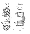
- the contact eyelet 6 in more detail.
- This consists of a flat, essentially rectangular metal piece 140 which has a contact surface 141 in the region of its one end, which is riveted into a bore 146.
- the contact eyelet is inserted into the housing via a lug 143 and a slightly rounded recess 144 provided on the corresponding opposite side.
- a central bore 145 and a longitudinal recess 142 can also be provided, the latter serving as a soldering lug.
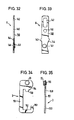
- 34 and 35 show the contact rocker 3.
- This is also made from a flat piece of metal, which has the following shape: an elongated leg 151 opens into a shorter, transverse leg 152, from which in turn a short leg 153 is at right angles upwards ( 34) protrudes and is therefore parallel to the leg 151.
- a leg 154 protrudes parallel to the leg 152 and is significantly wider than the leg 152.
- This leg 154 carries the contact surface 20, which is riveted to a bore 155.
- the leg 154 has a nose 150 projecting toward the leg 152, on which the spring 5 is guided and supported.
- the support eyelet 4 also consists of an elongated and flat metal piece 160 which has a widening 165, whereby an edge 164 is formed. The housing closing plate of the fully assembled switch rests on this edge.
- the lower end of the thickening 165 has a recess 166.
- the support eyelet has a rectangular recess 163 approximately in its center. The contact rocker is now inserted into the support eyelet so that the leg 153 is guided in the recess 166, while the leg 151 lies in the recess 163.
- the leg 152 thus runs parallel to the wall of the thickened part 165.
- the support eyelet also has an approximately rectangular recess 161, which serves as a soldering eyelet.
- the support eye can also have a bore *, similar to the bore 145 of the contact eye 6.
- This insulating lever has an essentially cylindrical base body 171 which has a central bore 170. This bore 170 is guided on the outer wall of the bolt 13, while the outside of the cylindrical base body 171 is guided in the recess 28 (FIG. 7) of the housing closing plate.
- a lug 172 protrudes from the base body 171, which is narrower than the cylindrical base body 171. Specifically, the width of the lug 172 is adapted to the width of the recess 25 (FIG. 7), while the entire width of the insulating material lever corresponds to the width of the sum corresponds to the two recesses 28 and 25.
- the nose 172 has two substantially parallel edges 173 and 174, which are connected to one another via an inclined wall 175.
- the two walls 173 and 174 run here at an acute angle to a radius of the bore 170, the wall 174 opening tangentially into the outer circumference of the cylindrical base body 171.
- the wall 173 forms the stop for the pin 11, which can run past the outer circumference of the cylindrical base body 171 until it abuts the wall 173.
- a further projection 176 is attached to the cylindrical base body 171 approximately opposite the lug 172, the thickness of this projection 176 corresponding to the thickness of the lug 172.
- the lug 12 Perpendicularly from the projection 176, the lug 12 protrudes parallel to the axis of the bore 170 and is essentially cuboid.
- This nose 12 projects into the pivoting range of the contact rocker and presses it when the insulating material lever is pivoted out of its contact position.
- the spring arm 22 is attached in one piece to the projection 176, this spring arm forming an acute angle with the nose 172.
- the entire insulating material lever is a one-piece molded part made of plastic.
- the locking wire 40 and 41 show the locking wire, which has a circular cross-section and essentially an S-shaped shape in the side view. Specifically, the legs 181 and 182 point essentially at right angles from the middle leg 180, whereby they are each bent on two different sides and are therefore antiparallel to one another.
Priority Applications (1)
| Application Number | Priority Date | Filing Date | Title |
|---|---|---|---|
| AT82110371T ATE30487T1 (de) | 1981-12-17 | 1982-11-10 | Elektrischer schiebeschalter. |
Applications Claiming Priority (2)
| Application Number | Priority Date | Filing Date | Title |
|---|---|---|---|
| DE3150046 | 1981-12-17 | ||
| DE3150046A DE3150046C2 (de) | 1981-12-17 | 1981-12-17 | Elektrischer Schiebeschalter |
Publications (3)
| Publication Number | Publication Date |
|---|---|
| EP0081682A2 true EP0081682A2 (fr) | 1983-06-22 |
| EP0081682A3 EP0081682A3 (en) | 1985-10-30 |
| EP0081682B1 EP0081682B1 (fr) | 1987-10-28 |
Family
ID=6149011
Family Applications (1)
| Application Number | Title | Priority Date | Filing Date |
|---|---|---|---|
| EP82110371A Expired EP0081682B1 (fr) | 1981-12-17 | 1982-11-10 | Interrupteur électrique à curseur |
Country Status (4)
| Country | Link |
|---|---|
| US (1) | US4472612A (fr) |
| EP (1) | EP0081682B1 (fr) |
| AT (1) | ATE30487T1 (fr) |
| DE (2) | DE3150046C2 (fr) |
Cited By (3)
| Publication number | Priority date | Publication date | Assignee | Title |
|---|---|---|---|---|
| EP0645790A2 (fr) * | 1993-09-27 | 1995-03-29 | FABEG GmbH | Dispositif pour l'actionnement des interrupteurs de fin de course dans un entraînement d'ajustement linéaire commandé par moteur électrique |
| EP0727795A2 (fr) * | 1995-02-17 | 1996-08-21 | Honeywell Inc. | Commutateur à plusieurs étages avec mécanisme d'ouverture positive |
| EP0777243A3 (fr) * | 1995-11-28 | 1998-05-13 | Schulte-Elektrotechnik GmbH & Co. KG | Interrupteur électrique |
Families Citing this family (3)
| Publication number | Priority date | Publication date | Assignee | Title |
|---|---|---|---|---|
| DE3336338A1 (de) * | 1983-10-06 | 1985-04-18 | Marquardt Gmbh, 7201 Rietheim-Weilheim | Elektrischer schalter |
| DE4301192C1 (de) * | 1993-01-19 | 1994-02-03 | Preh Elektro Feinmechanik | Drucktastenschalter |
| DE4428285C1 (de) * | 1994-08-10 | 1995-07-06 | Preh Elektro Feinmechanik | Drucktastenschalter |
Citations (3)
| Publication number | Priority date | Publication date | Assignee | Title |
|---|---|---|---|---|
| DE1935225A1 (de) * | 1969-07-11 | 1971-02-04 | Siemens Ag | Elektrischer Schnappschalter |
| DE2228096A1 (de) * | 1972-06-09 | 1973-12-20 | Schiele Verwaltungsgmbh | Elektrischer, mechanisch betaetigter sprungschalter |
| FR2308182A1 (fr) * | 1975-04-14 | 1976-11-12 | Telemecanique Electrique | Micro-rupteur a commande positive |
Family Cites Families (6)
| Publication number | Priority date | Publication date | Assignee | Title |
|---|---|---|---|---|
| US1810931A (en) * | 1927-10-10 | 1931-06-23 | Howard A Spahr | Electric switch |
| DE1085217B (de) * | 1958-03-31 | 1960-07-14 | Licentia Gmbh | Schalter mit Kontaktdruckerhoehung durch Ausnutzung der Kontaktfederreaktionskraft |
| GB1114630A (en) * | 1965-05-20 | 1968-05-22 | Schaltbau Gmbh | Quick action electric switch |
| US3330924A (en) * | 1965-11-24 | 1967-07-11 | Cutler Hammer Inc | Contact mounting structure for electric switches |
| CH580862A5 (fr) * | 1973-08-16 | 1976-10-15 | Sodeco Compteurs De Geneve | |
| IT1141172B (it) * | 1980-02-06 | 1986-10-01 | Cge Cie Generale Elettromeccan | Interruttore elettrico a scatto rapido con apertura forzata dei contatti |
-
1981
- 1981-12-17 DE DE3150046A patent/DE3150046C2/de not_active Expired
-
1982
- 1982-11-10 AT AT82110371T patent/ATE30487T1/de active
- 1982-11-10 DE DE8282110371T patent/DE3277557D1/de not_active Expired
- 1982-11-10 EP EP82110371A patent/EP0081682B1/fr not_active Expired
- 1982-11-24 US US06/444,337 patent/US4472612A/en not_active Expired - Fee Related
Patent Citations (3)
| Publication number | Priority date | Publication date | Assignee | Title |
|---|---|---|---|---|
| DE1935225A1 (de) * | 1969-07-11 | 1971-02-04 | Siemens Ag | Elektrischer Schnappschalter |
| DE2228096A1 (de) * | 1972-06-09 | 1973-12-20 | Schiele Verwaltungsgmbh | Elektrischer, mechanisch betaetigter sprungschalter |
| FR2308182A1 (fr) * | 1975-04-14 | 1976-11-12 | Telemecanique Electrique | Micro-rupteur a commande positive |
Cited By (5)
| Publication number | Priority date | Publication date | Assignee | Title |
|---|---|---|---|---|
| EP0645790A2 (fr) * | 1993-09-27 | 1995-03-29 | FABEG GmbH | Dispositif pour l'actionnement des interrupteurs de fin de course dans un entraînement d'ajustement linéaire commandé par moteur électrique |
| EP0645790A3 (fr) * | 1993-09-27 | 1995-09-06 | Fabeg Gmbh | Dispositif pour l'actionnement des interrupteurs de fin de course dans un entraînement d'ajustement linéaire commandé par moteur électrique. |
| EP0727795A2 (fr) * | 1995-02-17 | 1996-08-21 | Honeywell Inc. | Commutateur à plusieurs étages avec mécanisme d'ouverture positive |
| EP0727795A3 (fr) * | 1995-02-17 | 1997-11-12 | Honeywell Inc. | Commutateur à plusieurs étages avec mécanisme d'ouverture positive |
| EP0777243A3 (fr) * | 1995-11-28 | 1998-05-13 | Schulte-Elektrotechnik GmbH & Co. KG | Interrupteur électrique |
Also Published As
| Publication number | Publication date |
|---|---|
| US4472612A (en) | 1984-09-18 |
| EP0081682B1 (fr) | 1987-10-28 |
| DE3150046C2 (de) | 1984-05-10 |
| EP0081682A3 (en) | 1985-10-30 |
| DE3277557D1 (en) | 1987-12-03 |
| ATE30487T1 (de) | 1987-11-15 |
| DE3150046A1 (de) | 1983-07-14 |
Similar Documents
| Publication | Publication Date | Title |
|---|---|---|
| DE2706463A1 (de) | Druckknopfschalter fuer elektrische rechner u.dgl. | |
| DE1129587B (de) | Elektrischer Schnappschalter mit zwei unter Zugfederspannung am Stoessel gehalterten Kontaktarmen | |
| EP1764813B1 (fr) | Interrupteur électrique | |
| EP0173756B1 (fr) | Dispositif de contact | |
| DE102006031584A1 (de) | Miniaturisierter elektrischer Schalter | |
| DE2018427A1 (de) | Druckknopfschalter | |
| EP0081682B1 (fr) | Interrupteur électrique à curseur | |
| EP0099019A1 (fr) | Relais avec ressort de contact de pontage | |
| DE2541922A1 (de) | Verriegelter drucktastenschalter | |
| DE2416969C2 (de) | Druckknopfschalter | |
| DE102015110641B3 (de) | Elektrisches Schaltgerät | |
| AT409428B (de) | Elektrischer installationsschalter | |
| DE2939583A1 (de) | Drucktastenschalter mit beweglichem schieber | |
| DE3324253C2 (fr) | ||
| DE1910165C3 (de) | Zweipoliger Schiebeschalter | |
| DE2904646C2 (de) | Drucktastenschalter | |
| DE3940285C2 (fr) | ||
| DE4302185C1 (de) | Zweipoliger Schalter | |
| DE4324206C2 (de) | Elektrischer Schalter mit Schneidlager und Kontaktfeder | |
| DE4026292A1 (de) | Elektrischer druckknopf- bzw. -tastenschalter, insbesondere fuer kfz | |
| DE2151903B2 (de) | Kontaktvorrichtung für elektrische Schaltgeräte oder Trennvorrichtungea | |
| DE2558620C2 (de) | Elektrischer Schalter | |
| AT402126B (de) | Vorrichtung zum befestigen eines elektrischen schaltgerätes auf einer tragschiene | |
| DE1971585U (de) | An isolationskoerpern gehaltenes festkontaktteil. | |
| DE2541034A1 (de) | Elektrischer schiebeschalter |
Legal Events
| Date | Code | Title | Description |
|---|---|---|---|
| PUAI | Public reference made under article 153(3) epc to a published international application that has entered the european phase |
Free format text: ORIGINAL CODE: 0009012 |
|
| AK | Designated contracting states |
Designated state(s): AT CH DE FR GB IT LI NL SE |
|
| PUAL | Search report despatched |
Free format text: ORIGINAL CODE: 0009013 |
|
| AK | Designated contracting states |
Designated state(s): AT CH DE FR GB IT LI NL SE |
|
| 17P | Request for examination filed |
Effective date: 19851210 |
|
| 17Q | First examination report despatched |
Effective date: 19861211 |
|
| GRAA | (expected) grant |
Free format text: ORIGINAL CODE: 0009210 |
|
| ITF | It: translation for a ep patent filed |
Owner name: DR. ING. A. RACHELI & C. |
|
| AK | Designated contracting states |
Kind code of ref document: B1 Designated state(s): AT CH DE FR GB IT LI NL SE |
|
| REF | Corresponds to: |
Ref document number: 30487 Country of ref document: AT Date of ref document: 19871115 Kind code of ref document: T |
|
| PGFP | Annual fee paid to national office [announced via postgrant information from national office to epo] |
Ref country code: NL Payment date: 19871130 Year of fee payment: 6 |
|
| REF | Corresponds to: |
Ref document number: 3277557 Country of ref document: DE Date of ref document: 19871203 |
|
| ET | Fr: translation filed | ||
| GBT | Gb: translation of ep patent filed (gb section 77(6)(a)/1977) | ||
| PLBE | No opposition filed within time limit |
Free format text: ORIGINAL CODE: 0009261 |
|
| STAA | Information on the status of an ep patent application or granted ep patent |
Free format text: STATUS: NO OPPOSITION FILED WITHIN TIME LIMIT |
|
| 26N | No opposition filed | ||
| PG25 | Lapsed in a contracting state [announced via postgrant information from national office to epo] |
Ref country code: GB Effective date: 19891110 Ref country code: AT Effective date: 19891110 |
|
| PG25 | Lapsed in a contracting state [announced via postgrant information from national office to epo] |
Ref country code: SE Effective date: 19891111 |
|
| PG25 | Lapsed in a contracting state [announced via postgrant information from national office to epo] |
Ref country code: LI Effective date: 19891130 Ref country code: CH Effective date: 19891130 |
|
| PG25 | Lapsed in a contracting state [announced via postgrant information from national office to epo] |
Ref country code: NL Effective date: 19900601 |
|
| GBPC | Gb: european patent ceased through non-payment of renewal fee | ||
| NLV4 | Nl: lapsed or anulled due to non-payment of the annual fee | ||
| PG25 | Lapsed in a contracting state [announced via postgrant information from national office to epo] |
Ref country code: FR Effective date: 19900731 |
|
| REG | Reference to a national code |
Ref country code: CH Ref legal event code: PL |
|
| PG25 | Lapsed in a contracting state [announced via postgrant information from national office to epo] |
Ref country code: DE Effective date: 19900801 |
|
| REG | Reference to a national code |
Ref country code: FR Ref legal event code: ST |
|
| EUG | Se: european patent has lapsed |
Ref document number: 82110371.0 Effective date: 19900705 |