EP0081069B1 - Schaumstoffbahn aus einem geschlossenzellig geschäumten, vernetzten Kunststoffkörper - Google Patents
Schaumstoffbahn aus einem geschlossenzellig geschäumten, vernetzten Kunststoffkörper Download PDFInfo
- Publication number
- EP0081069B1 EP0081069B1 EP82109485A EP82109485A EP0081069B1 EP 0081069 B1 EP0081069 B1 EP 0081069B1 EP 82109485 A EP82109485 A EP 82109485A EP 82109485 A EP82109485 A EP 82109485A EP 0081069 B1 EP0081069 B1 EP 0081069B1
- Authority
- EP
- European Patent Office
- Prior art keywords
- foam web
- plastics body
- channels
- plastic body
- web according
- Prior art date
- Legal status (The legal status is an assumption and is not a legal conclusion. Google has not performed a legal analysis and makes no representation as to the accuracy of the status listed.)
- Expired
Links
- 239000004033 plastic Substances 0.000 title claims abstract description 34
- 229920003023 plastic Polymers 0.000 title claims abstract description 34
- 239000006260 foam Substances 0.000 title claims abstract description 24
- 239000000835 fiber Substances 0.000 claims description 16
- -1 polyethylene Polymers 0.000 claims description 10
- 239000004698 Polyethylene Substances 0.000 claims description 3
- 229920000573 polyethylene Polymers 0.000 claims description 3
- 229920000098 polyolefin Polymers 0.000 claims description 3
- 239000002985 plastic film Substances 0.000 claims 2
- 239000004744 fabric Substances 0.000 claims 1
- 239000002759 woven fabric Substances 0.000 claims 1
- 239000004743 Polypropylene Substances 0.000 description 7
- 229920001155 polypropylene Polymers 0.000 description 7
- 238000010521 absorption reaction Methods 0.000 description 6
- 239000000463 material Substances 0.000 description 4
- 239000011148 porous material Substances 0.000 description 4
- 229920003020 cross-linked polyethylene Polymers 0.000 description 3
- 239000004703 cross-linked polyethylene Substances 0.000 description 3
- 230000000149 penetrating effect Effects 0.000 description 3
- XLYOFNOQVPJJNP-UHFFFAOYSA-N water Chemical compound O XLYOFNOQVPJJNP-UHFFFAOYSA-N 0.000 description 3
- 230000000694 effects Effects 0.000 description 2
- 238000004519 manufacturing process Methods 0.000 description 2
- 230000035699 permeability Effects 0.000 description 2
- 239000004793 Polystyrene Substances 0.000 description 1
- 239000004823 Reactive adhesive Substances 0.000 description 1
- 230000001154 acute effect Effects 0.000 description 1
- 238000004873 anchoring Methods 0.000 description 1
- 239000011230 binding agent Substances 0.000 description 1
- 210000004027 cell Anatomy 0.000 description 1
- 210000002421 cell wall Anatomy 0.000 description 1
- 230000006835 compression Effects 0.000 description 1
- 238000007906 compression Methods 0.000 description 1
- 238000009413 insulation Methods 0.000 description 1
- 238000000034 method Methods 0.000 description 1
- 239000000203 mixture Substances 0.000 description 1
- 230000003287 optical effect Effects 0.000 description 1
- 238000006068 polycondensation reaction Methods 0.000 description 1
- 238000006116 polymerization reaction Methods 0.000 description 1
- 229920002223 polystyrene Polymers 0.000 description 1
- 230000002035 prolonged effect Effects 0.000 description 1
- 230000006641 stabilisation Effects 0.000 description 1
- 238000011105 stabilization Methods 0.000 description 1
- 229920001169 thermoplastic Polymers 0.000 description 1
- 239000004416 thermosoftening plastic Substances 0.000 description 1
Images
Classifications
-
- B—PERFORMING OPERATIONS; TRANSPORTING
- B29—WORKING OF PLASTICS; WORKING OF SUBSTANCES IN A PLASTIC STATE IN GENERAL
- B29C—SHAPING OR JOINING OF PLASTICS; SHAPING OF MATERIAL IN A PLASTIC STATE, NOT OTHERWISE PROVIDED FOR; AFTER-TREATMENT OF THE SHAPED PRODUCTS, e.g. REPAIRING
- B29C44/00—Shaping by internal pressure generated in the material, e.g. swelling or foaming ; Producing porous or cellular expanded plastics articles
- B29C44/02—Shaping by internal pressure generated in the material, e.g. swelling or foaming ; Producing porous or cellular expanded plastics articles for articles of definite length, i.e. discrete articles
- B29C44/12—Incorporating or moulding on preformed parts, e.g. inserts or reinforcements
Definitions
- the invention relates to a foam web, consisting of a closed-cell foamed, cross-linked plastic body, which has an underside which extends essentially parallel to the upper side, in which the upper and / or the underside through channels penetrating into the plastic body and distributed in a pattern over the surface interrupted with needles in it.
- GB-A-986 077 refers to a foam sheet of the aforementioned type.
- the channels contained therein are delimited by the walls of the pores of the plastic body cut by the needling process and show a correspondingly strong fissure.
- they are unable to give the needled fibers, which naturally have a relatively smooth surface, a good hold. This severely limits the possibilities of using corresponding foam webs.
- the object of the present invention is aimed at showing a foam sheet which advantageously differs from an embodiment of the type mentioned above.
- the needled fibers in the plastic body are at least simply crimped.
- the fibers have, at least in part, a course extending transversely to the direction of the channels and a greater extent in this direction than the channels.
- Their axial fixation in the channels is significantly improved. Unintentional removal or falling out of the fibers from the channels is no longer possible, which allows the foam web according to the invention to be used for new and improved applications, for example for use in the production of high-quality insoles.
- the fibers can be embedded in a plastic body with soft elastic properties and in this case are only connected by the plastic body. They are unable to hinder deformation under the influence of pressure and heat, but they provide excellent stabilization of the spatial structure of the foam, thereby preventing changes in properties during the deformation.
- the channels interrupting the top and / or bottom side can penetrate into the foam sheet vertically or obliquely to extend in the manner of blind holes. You can penetrate them completely so that one mouth interrupts the top and the other mouth interrupts the bottom.
- each channel has several mouths in the area of the top and / or bottom.
- the individual subchannels enclose an acute angle with the extension of the foam sheet. Effects in which a special design of the surface is important, such as the absorbency or permeability to airborne sound or moisture, can be significantly enhanced.
- the channels consist of circular or polygonal holes that are created without removing material components. After the fibers have been stored, this results in a mutual compression between the fibers and the inner wall of the channels.
- the latter consists essentially of the walls of the cut, spherical pores of the foam, and it shows a correspondingly strong fissure, which is advantageous for the definition of the crimped fibers and in view of achieving a good absorption capacity.
- the latter can be further increased by using fibers with an open pore structure.
- the parts of the cut cell walls protruding into the channels are extremely supple and are able to penetrate into the finest irregularities in the surface of the embedded fibers. This gives them additional security with regard to anchoring.
- the fibers can additionally be adhesively connected to the wall of the channels, for example by thermoplastic softening of the plastic body or with the aid of a reactive adhesive. In both cases, particularly good homogeneity of the mechanical properties is achieved.
- the plastic body can consist of a closed-cell foamed, crosslinked polyolefin, for example of polyethylene, polypropylene or a blend of both materials.
- polypropylene is characterized by greater hardness than polyethylene, but the latter has a better absorbency for airborne sound.
- Foam sheets made of polymeric materials created by polycondensation, polymerization or polyaddition, can also be used (e.g. PVC, EVA, polystyrene, etc.). By using these foams, certain mechanical, electrical and optical properties can be achieved in a targeted manner (e.g. tensile strength, modulus of elasticity, dimensional stability, behavior when heated, insulation behavior, etc.).
- the plastic body 1 according to FIG. 1 consists of a closed-cell foamed, cross-linked polyethylene with a density of 70 kg / m 3 .
- the thickness is 10 mm.
- the plastic body 1 is completely penetrated by vertical channels 2 which are uniformly distributed over the entire surface in a pattern. These have a circular profile recognizable in the area of the top and in the area of the underside and a mutual center point distance of 2 mm.
- the profile of the channels 2 shows a strong fissure due to the large number of cut, originally spherical cells.
- the channels 2 penetrating the plastic body 1 according to FIG. 2 are bent approximately at a right angle in the middle of the plastic body and contain bundles of crimped polypropylene fibers which are integrated into a fleece placed on the underside. This greatly increases the absorption capacity.
- the fleece is also made of polypropylene fibers and has a thickness of 3 mm at a basis weight of 150 g / m 2 . With good elasticity, it is characterized by complete freedom from binding agents.
- the moisture absorption capacity of polypropylene is negligible. Nevertheless, due to the capillary activity between the individual polypropylene fibers, the foam sheet according to FIG. 2 has good permeability to water vapor.
- the pore system of the fleece layer arranged on the underside is directly connected to that of the fibers contained in the channels 2. As a result, the bottom has a larger capacity than the top, both with regard to the absorption and with the delivery of water vapor per unit of time. Absorbed moisture is preferably stored in this area. For example, an appropriately designed insole thus has a dry-appearing surface even after prolonged use, and the moisture absorbed can evaporate quickly over the free underside after the insole has been removed from the shoe.
- FIG. 3 shows a plastic body 1 made of a closed-cell foamed, cross-linked polyethylene with a thickness of 15 mm.
- the top and bottom of the plastic body 1 are interrupted by alternately vertically penetrating, blind-hole-shaped channels 2.
- the closed end of the channels is at a distance of 1.5 mm from the opposite side of the plastic body 1.
- the channels 2 have a circular profile with a diameter of 3 mm, which can be seen at the mouth.
- the mutual center distance is 12 mm.
- Figure 4 shows a plastic body 1 similar to Figure 3, with the difference that the plastic body 1 is a closed-cell foamed, cross-linked polypropylene with a density of 150 kg / m3.
- the thickness is 10 mm, and the mouths of the channels 2 are arranged only side by side on the top.
- the underside of the plastic body 1 is laminated onto a carrier plate 6, which enables easy attachment when used as a sound absorbing mat.
- the plastic body 1 according to FIG. 5 consists of a sheet of a closed-cell foamed, cross-linked polyethylene with a density of 90 kg / m 3 .
- the thickness is 8 mm, and the upper side shows the openings of channels 2 which merge into one another inside the plastic body 1.
- the material is rot-proof, has a textile-like soft surface and good water absorption. For this reason, it is ideal for the production of high-quality insoles.
- Figure 6 shows the top of a plastic body 1, which is interrupted by a plurality of channel openings assigned in a pattern.
- the profile is triangular, but only clearly recognizable in the area of the actual mouth of the channels 2, because here the foam sheet is finished in a uniform, foil-like manner.
- the profile has a similar fissure on the inside as shown in FIG.
Landscapes
- Laminated Bodies (AREA)
- Manufacture Of Porous Articles, And Recovery And Treatment Of Waste Products (AREA)
- Braking Arrangements (AREA)
- Absorbent Articles And Supports Therefor (AREA)
- Cleaning Implements For Floors, Carpets, Furniture, Walls, And The Like (AREA)
- Steroid Compounds (AREA)
- Medicines Containing Material From Animals Or Micro-Organisms (AREA)
- Nonwoven Fabrics (AREA)
- Manufacturing Of Micro-Capsules (AREA)
- Materials For Medical Uses (AREA)
- Brushes (AREA)
- Molding Of Porous Articles (AREA)
Description
- Die Erfindung betrifft eine Schaumstoffbahn, bestehend aus einem geschlossenzellig geschäumten, vernetzten Kunststoffkörper, der eine sich im wesentlichen parallel zu der Oberseite erstreckende Unterseite aufweist, bei dem die Ober- und/oder die Unterseite durch in den Kunststoffkörper eindringende, musterartig über die Fläche verteilte Kanäle mit darin eingenadelten Fasern unterbrochen ist.
- Auf eine Schaumstoffbahn der vorgenannten Art nimmt die GB-A-986 077 Bezug. Die darin enthaltenen Kanäle werden durch die Wandungen der durch den Nadelungsvorgang angeschnittenen Poren des Kunststoffkörpers begrenzt und zeigen eine dementaprechend starke Zerklüftung. Sie vermögen indessen den eingenadelten Fasern, die naturgemäß eine relativ glatte Oberfläche haben, keinen guten Halt zu verleihen. Die Verwendungsmöglichkeiten entsprechender Schaumstoffbahnen erfahren dadurch eine starke Beschränkung.
- Die Aufgabe der vorliegenden Erfindung ist darauf gerichtet, eine Schaumstoffbahn zu zeigen, die sich vorteilhaft von einer Ausführung der vorstehend angesprochenen Art unterscheidet.
- Diese Aufgabe wird erfindungsgemäß dadurch gelöst, daß die in den Kunststoffkörper eingenadelten Fasern wenigstens einfach gekräuselt sind. Die Fasern haben dadurch zumindest teilweise einen sich quer zur Richtung der Kanäle erstreckenden Verlauf und in dieser Richtung eine größere Ausdehnung als die Kanäle. Ihre axiale Festlegung in den Kanälen erfährt dadurch eine deutliche Verbesserung. Ein unbeabsichtigtes Herauslösen oder Herausfallen der Fasern aus den Kanälen ist nicht mehr möglich, was es erlaubt, die erfindungsgemäße Schaumstoffbahn neuen und verbesserten Anwendungen zuzuführen, beispielsweise einer Verwendung bei der Herstellung hochwertiger Einlegesohlen.
- Die Fasern können in einen Kunststoffkörper mit weichelastischen Eigenschaften eingebettet werden und sind in diesem Falle lediglich durch den Kunststoffkörper verbunden. Sie vermögen eine Umformung unter der Einwirkung von Druck und Wärme nicht zu behindern, bewirken jedoch eine ausgezeichnete Stabilisierung der Raumstruktur des Schaumstoffes, wodurch Veränderungen der Eigenschaften während des Umformens verhindert werden.
- Die die Ober- und/oder die Unterseite unterbrechenden Kanäle können nach Art von Sacklöchern senkrecht oder schräg zur Erstreckung in die Schaumstoffbahn eindringen. Sie können diese ganz durchdringen, so daß eine Mündung die Oberseite, die andere Mündung hingegen die Unterseite unterbricht.
- Sie können auch derart ineinander übergehen, daß jeder Kanal mehrere Mündungen im Bereich der Ober, und/oder der Unterseite aufweist. Die einzelnen Teilkanäle schließen in diesem Falle mit der Erstreckung der Schaumstoffbahn einen spitzen Winkel ein. Effekte, bei denen es auf eine besondere Gestaltung der Oberfläche maßgeblich ankommt, wie beispielsweise die Absorptionsfähigkleit oder Durchlässigkeit gegenüber Luftschall oder Feuchtigkeit, lassen sich hierdurch wesentlich verstärken.
- Die Kanäle bestehen aus kreis- oder polygonförmig ausgeführten Löchern, die ohne Entnahme von Werkstoffbestandteilen erzeugt sind. Nach der Einlagerung der Fasern ergibt sich hierdurch eine gegenseitige Verpressung zwischen den Fasern und der Innenwandung der Kanäle. Letztere besteht im wesentlichen aus den Wänden der angeschnittenen, kugelförmigen Poren des Schaumstoffes, und sie zeigt eine dementsprechend starke Zerklüftung, was für die Festlegung der gekräuselten Fasern sowie im Hinblick auf die Erzielung einer guten Absorptionskapazität von Vorteil ist. Letztere läßt sich weiter steigern durch die Verwendung von Fasern mit einer offenen Porenstruktur.
- Die in die Kanäle vorspringenden Teile der angeschnittenen Zellwände weisen eine große Anschmiegsamkeit auf und vermögen in feinste Unregelmäßigkeiten der Oberfläche der eingelagerten Fasern einzudringen. Diese erfahren dadurch eine zusätzliche Sicherung hinsichtlich der Verankerung.
- Die Fasern können zusätzlich auf adhäsive Weise mit der Wandung der Kanäle verbunden werden, beispielsweise durch thermoplastische Erweichung des Kunststoffkörpers oder unter Zuhilfenahme eines reaktiven Klebstoffes. In beiden Fällen wird eine besonders gute Homogenität der mechanischen Eigenschaften erzielt.
- Der Kunststoffkörper kann aus einem geschlossenzellig geschäumten, vernetzten Polyolefin bestehen, beispielsweise aus Polyethylen, Polypropylen oder einem Verschnitt aus beiden Werkstoffen. Polypropylen zeichnet sich neben einer verbesserten Temperaturbeständigkeit durch eine größere Härte gegenüber Polyethylen aus, letzteres besitzt jedoch ein besseres Absorptionsvermögen für Luftschall. In Abhängigkeit von dem vorgesehenen Verwendungszweck ist es deshalb unerläßlich, eine fachkundige Auswahl zu treffen. Es können auch Schaumstoffbahnen aus polymeren Werkstoffen, entstanden durch Polykondensation, Polymerisation oder Polyaddition, verwendet werden (z.B. PVC, EVA, Polystyrol usw). Durch den Einsatz dieser Schaumstoffe können bestimmte mechanische, elektrische und optische Eigenschaften gezielt erreicht werden (z.B. Zugfestigkeit, E-Modul, Formbeständigkeit, Verhalten bei Erwärmung, Isolationsverhalten usw.).
- Der Gegenstand der vorliegenden Erfindung wird anhand der in der Anlage beigefügten Zeichnungen nachfolgend weiter erläutert.
- Es zeigen:
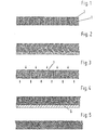
- Figuren 1 bis 5 unterschiedliche Zuordnungen der Kanäle zum Profil des Kunststoffkörpers.
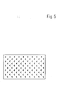
- Figur 6 die Oberseite des Kunststoffkörpers zur Verdeutlichung einer möglichen gegenseitigen Zuordnung der Lage der einzelnen Kanäle.
- Der Kunststoffkörper 1 gemäß Figur 1 besteht aus einem geschlossenzellig geschäumten, vernetzten Polyethylen mit einem Raumgewicht von 70 kg/m3. Die Dicke beträgt 10 mm.
- Der Kunststoffkörper 1 ist von musterartig über die gesamte Oberfläche gleichmäßig verteilten, senkrechten Kanälen 2 ganz durchdrungen. Diese haben ein im Bereich der Ober- und im Bereich der Unterseite erkennbares, kreisförmiges Profil und einen gegenseitigen Mittelpunktsabstand von 2 mm.
- Das Profil der Kanäle 2 zeigt durch die Vielzahl der angeschnittenen, ursprünglich kugelförmig ausgebildeten Zellen eine starke Zerklüftung.
- Die absorptionswirksame Oberfläche ist dadurch stark vergrößert.
- Die den Kunststoffkörper 1 gemäß Figur 2 durchdringenden Kanäle 2 sind etwa in der Mitte des Kunststoffkörpers unter einem rechten Winkel abgeknickt und enthalten Bündel aus gekräuselten Polypropylenfasern, die in ein auf die Unterseite aufgelegtes Vlies eingebunden sind. Die Absorptionskapazität ist hierdurch stark vergrößert. Das Vlies besteht ebenfalls aus Polypropylenfasern, und hat bei einem Flächengewicht von 150 g/m2 eine Dicke von 3 mm. Es zeichnet sich bei einer guten Sprungelastizität durch völlige Bindemittelfreiheit aus.
- Die Feuchtigkeitsaufnahmefähigkeit von Polypropylen ist vernachlässigbar gering. Dennoch weist die Schaumstoffbahn gemäß Figur 2 infolge der zwischen den einzelnen Polypropylenfasern wirksamen Kapillaraktivität eine gute Durchlässigkeit für Wasserdampf auf. Das Porensystem der auf der Unterseite angeordneten Vliesschicht ist unmittelbar mit demjenigen der in den Kanälen 2 enthaltenen Fasern verbunden. Sowohl hinsichtlich der Aufnahme als auch hinsichtlich der Abgabe von Wasserdampf je Zeiteinheit weist infolgedessen die Unterseite eine größere Kapazität auf als die Oberseite. Aufgenommene Feuchtigkeit wird dadurch bevorzugt in diesem Bereich gespeichert. Beispielsweise eine entsprechend ausgebildete Einlegesohle weist dadurch auch nach längerem Gebrauch eine trocken erscheinende Oberfläche auf und die aufgenommene Feuchtigkeit kann nach dem Herausnehmen der Einlegesohle aus dem Schuh in kurzer Zeit über die freie Unterseite verdunsten.
- Figur 3 zeigt einen Kunststoffkörper 1 aus einem geschlossenzellig geschäumten, vernetzten Polyethylen mit einer Dicke von 15 mm. Ober- und Unterseite des Kunststoffkörpers 1 sind durch abwechselnd senkrecht eindringende, sacklochartig ausgebildete Kanäle 2 unterbrochen. Das geschlossene Ende der Kanäle hat jeweils einen Abstand von 1,5 mm von der gegenüberliegenden Seite des Kunststoffkörpers 1. Die Kanäle 2 haben ein an der Mündung erkennbares, kreisförmiges Profil mit einem Durchmesser von 3 mm. Der gegenseitige Achsabstand beträgt 12 mm.
- Figur 4 zeigt einen Kunststoffkörper 1 ähnlich Figur 3, mit dem Unterschied, daß der Kunststoffkörper 1 ein geschlossenzellig geschäumtes, vernetztes Polypropylen mit einem Raumgewicht von 150 kg/m3 ist. Die Dicke beträgt 10 mm, und die Mündungen der Kanäle 2 sind ausschließlich nebeneinanderliegend auf der Oberseite angeordnet. Die Unterseite des Kunststoffkörpers 1 ist auf ein Trägerblech 6 aufkaschiert, das eine leichte Anbringung bei der Verwendung als Schallschluckmatte ermöglicht.
- Der Kunststoffkörper 1 gemäß Figur 5 besteht aus einer Bahn aus einem geschlossenzellig geschäumten, vernetzten Polyethylen mit einem Raumgewicht von 90 kg/m3. Die Dicke beträgt 8 mm, und die Oberseite zeigt die Mündungen von im Inneren des Kunststoffkörpers 1 ineinander übergehenden Kanälen 2.
- Das Material ist verrottungsfest, hat eine textilartig weiche Oberfläche und eine gute Wasseraufnahmefähigkeit. Es eignet sich aus diesem Grunde ausgezeichnet für die Herstellung hochwertiger Einlegesohlen.
- Figur 6 zeigt die Oberseite eines Kunststoffkörpers 1, welcher durch eine Vielzahl von musterartig zugeordneten Kanalmündungen unterbrochen ist. Das Profil ist dreieckig ausgebildet, jedoch nur im Bereich der eigentlichen Mündung der Kanäle 2 klar erkennbar, weil hier die Schaumstoffbahn einheitlich, folienartig abgeschlossen ist. Im Inneren weist das Profil demgegenüber eine ähnliche Zerklüftung auf wie in Figur 1 gezeigt.
Claims (9)
Priority Applications (1)
| Application Number | Priority Date | Filing Date | Title |
|---|---|---|---|
| AT82109485T ATE21854T1 (de) | 1981-12-09 | 1982-10-14 | Schaumstoffbahn aus einem geschlossenzellig geschaeumten, vernetzten kunststoffkoerper. |
Applications Claiming Priority (2)
| Application Number | Priority Date | Filing Date | Title |
|---|---|---|---|
| DE3148710A DE3148710C2 (de) | 1981-12-09 | 1981-12-09 | Schaumstoffbahn |
| DE3148710 | 1981-12-09 |
Publications (3)
| Publication Number | Publication Date |
|---|---|
| EP0081069A2 EP0081069A2 (de) | 1983-06-15 |
| EP0081069A3 EP0081069A3 (en) | 1984-08-01 |
| EP0081069B1 true EP0081069B1 (de) | 1986-09-03 |
Family
ID=6148255
Family Applications (1)
| Application Number | Title | Priority Date | Filing Date |
|---|---|---|---|
| EP82109485A Expired EP0081069B1 (de) | 1981-12-09 | 1982-10-14 | Schaumstoffbahn aus einem geschlossenzellig geschäumten, vernetzten Kunststoffkörper |
Country Status (10)
| Country | Link |
|---|---|
| EP (1) | EP0081069B1 (de) |
| JP (1) | JPS58101045A (de) |
| AT (1) | ATE21854T1 (de) |
| AU (1) | AU8577182A (de) |
| BR (1) | BR8204943A (de) |
| DE (2) | DE3148710C2 (de) |
| ES (1) | ES517967A0 (de) |
| FI (1) | FI78259C (de) |
| NO (1) | NO162501C (de) |
| ZA (1) | ZA827860B (de) |
Families Citing this family (5)
| Publication number | Priority date | Publication date | Assignee | Title |
|---|---|---|---|---|
| DE69210997T3 (de) † | 1991-04-30 | 1999-12-16 | The Dow Chemical Co., Midland | Perforierter plastikschaum und sein herstellungsverfahren |
| DE9321356U1 (de) * | 1993-01-28 | 1997-07-17 | Saar-Gummiwerk GmbH, 66687 Wadern | Elastische Schienenunterlage |
| DE4302299A1 (de) * | 1993-01-28 | 1994-08-04 | Saar Gummiwerk Gmbh | Elastische Schotterbettunterlage |
| AT507850B1 (de) | 2009-01-22 | 2016-01-15 | Eurofoam Gmbh | Schaumstoffelement mit darin eingelagerten hydrophilen mitteln |
| AT507849B1 (de) * | 2009-01-22 | 2011-09-15 | Eurofoam Gmbh | Schaumstoffelement mit darin eingelagerter zellulose |
Family Cites Families (12)
| Publication number | Priority date | Publication date | Assignee | Title |
|---|---|---|---|---|
| US2429486A (en) * | 1944-12-23 | 1947-10-21 | Bigelow Sanford Carpet Co Inc | Punched felt floor covering and process of making the same |
| US3122141A (en) * | 1962-03-29 | 1964-02-25 | Johnson & Johnson | Flexible absorbent sheet |
| GB1051320A (en) * | 1964-01-13 | 1966-12-14 | W.R. Grace & Co. | Micro-porous polyethylene and a process for the manufacture thereof |
| DE1719053B1 (de) * | 1964-12-15 | 1971-01-07 | Schickedanz Ver Papierwerk | Weicher,zellstoffhaltiger Polyurethanschaumstoff sowie Verfahren zu dessen Herstellung |
| US3366529A (en) * | 1967-02-21 | 1968-01-30 | Kendall & Co | Needled non-woven fabrics and method of making the same |
| US3532588A (en) * | 1967-04-12 | 1970-10-06 | Kendall & Co | Needled nonwoven textile laminate |
| CH507799A (de) * | 1969-04-25 | 1971-05-31 | Breveteam Sa | Schaumstoffkörper und Verfahren zu seiner Herstellung |
| DE1941838A1 (de) * | 1969-08-16 | 1971-02-25 | Collo Rheincollodium Koeln Gmb | Verfahren zum Herstellen von Verbundstoffen,insbesondere solchen fuer die Oberflaechenbearbeitung |
| GB1443732A (en) * | 1973-08-03 | 1976-07-21 | Shell Int Research | Method of producing an article of fibre-reinforced polyurethane foam |
| GB1425592A (en) * | 1973-09-26 | 1976-02-18 | Furukawa Electric Co Ltd | Method for the manufacture of cross-linked polyolefin foams having a very fine and uniform closed cell structure |
| DE2930007C2 (de) * | 1979-07-24 | 1981-11-12 | Alkor GmbH Kunststoffverkauf, 8000 München | Verfahren zur Herstellung einer beflockten Bahn |
| JPS55159946A (en) * | 1979-05-31 | 1980-12-12 | Matsushita Electric Works Ltd | Forming method for heat-insulating material |
-
1981
- 1981-12-09 DE DE3148710A patent/DE3148710C2/de not_active Expired
-
1982
- 1982-06-04 NO NO821876A patent/NO162501C/no unknown
- 1982-06-10 FI FI822069A patent/FI78259C/fi not_active IP Right Cessation
- 1982-07-09 AU AU85771/82A patent/AU8577182A/en not_active Abandoned
- 1982-08-24 BR BR8204943A patent/BR8204943A/pt unknown
- 1982-09-17 JP JP57162091A patent/JPS58101045A/ja active Pending
- 1982-10-14 EP EP82109485A patent/EP0081069B1/de not_active Expired
- 1982-10-14 DE DE8282109485T patent/DE3273043D1/de not_active Expired
- 1982-10-14 AT AT82109485T patent/ATE21854T1/de not_active IP Right Cessation
- 1982-10-27 ZA ZA827860A patent/ZA827860B/xx unknown
- 1982-12-06 ES ES517967A patent/ES517967A0/es active Granted
Also Published As
| Publication number | Publication date |
|---|---|
| EP0081069A3 (en) | 1984-08-01 |
| EP0081069A2 (de) | 1983-06-15 |
| FI78259B (fi) | 1989-03-31 |
| JPS58101045A (ja) | 1983-06-16 |
| FI822069L (fi) | 1983-06-10 |
| NO162501B (no) | 1989-10-02 |
| AU8577182A (en) | 1983-06-16 |
| NO821876L (no) | 1983-06-10 |
| NO162501C (no) | 1990-01-10 |
| ES8401885A1 (es) | 1984-01-01 |
| ES517967A0 (es) | 1984-01-01 |
| ATE21854T1 (de) | 1986-09-15 |
| BR8204943A (pt) | 1984-04-03 |
| DE3148710C2 (de) | 1986-02-27 |
| FI822069A0 (fi) | 1982-06-10 |
| DE3148710A1 (de) | 1983-07-21 |
| FI78259C (fi) | 1989-07-10 |
| DE3273043D1 (en) | 1986-10-09 |
| ZA827860B (en) | 1983-08-31 |
Similar Documents
| Publication | Publication Date | Title |
|---|---|---|
| DE69612012T2 (de) | Verbundwerkstoff zur verwendung bei der herstellung des shuhwerks | |
| EP0071212B1 (de) | Mattenförmiger Schichtkörper und Verfahren zu seiner Herstellung | |
| EP0204029B1 (de) | Deck- oder Einlegesohle | |
| DE19704334B4 (de) | Textiles Dämpfungsmaterial und daraus hergestellte Golfabschlagmatte | |
| EP0272366A2 (de) | Medizinischer Saugkörper mit Röntgenkontrastmittel und Verfahren zu seiner Herstellung | |
| EP0609715A1 (de) | Fahrzeugsitz, insbesondere für Flugzeuge | |
| DE3546114A1 (de) | Fasermatten-belag mit verbesserten durchschlag-widerstand | |
| DE3620388A1 (de) | Draenmatte mit hoher druckbestaendigkeit | |
| DE69508491T2 (de) | Poröser Scheuergegenstand, Reinigungseinrichtung und Herstellungsverfahren | |
| WO1999044816A1 (de) | Schichtstoff | |
| DE102013104715A1 (de) | Hinterschäumbares Akustikelement eines Kraftfahrzeugkarosserieverkleidungsbauteils | |
| EP0081069B1 (de) | Schaumstoffbahn aus einem geschlossenzellig geschäumten, vernetzten Kunststoffkörper | |
| EP4525796B1 (de) | Wundauflage | |
| EP0069323A1 (de) | Filtermatte, insbesondere für Küchendunsthauben u.dgl. und Verfahren zu ihrer Herstellung | |
| DE3022461A1 (de) | Mehrschichtige entdroehnbelagsbahn fuer karosseriebleche | |
| EP1587978B1 (de) | Textiles flächengebilde, und verfahren zu seiner herstellung und seiner verwendung | |
| DE2438531B2 (de) | Separatorenmaterial | |
| DE2648716C3 (de) | Teppichzwischenlage | |
| EP0053201B1 (de) | Reinigungstuch | |
| WO2018158351A1 (de) | Einlegesohle | |
| DE9422147U1 (de) | Mehrschichtkörper | |
| EP0081030A2 (de) | Schaumstoffbahn aus einem geschlossenzellig geschäumten Weichkunststoff | |
| DE2544033C3 (de) | Teppichunterlage | |
| DE8135826U1 (de) | Schaumstoffbahn aus einem geschlossenzellig geschaeumten, vernetzten kunststoffkoerper | |
| DE8135828U1 (de) | Schaumstoffbahn aus einem geschlossenzellig geschaeumten weichkunststoff |
Legal Events
| Date | Code | Title | Description |
|---|---|---|---|
| PUAI | Public reference made under article 153(3) epc to a published international application that has entered the european phase |
Free format text: ORIGINAL CODE: 0009012 |
|
| AK | Designated contracting states |
Designated state(s): AT BE CH DE FR GB IT LI NL SE |
|
| PUAL | Search report despatched |
Free format text: ORIGINAL CODE: 0009013 |
|
| AK | Designated contracting states |
Designated state(s): AT BE CH DE FR GB IT LI NL SE |
|
| 17P | Request for examination filed |
Effective date: 19840725 |
|
| ITF | It: translation for a ep patent filed | ||
| GRAA | (expected) grant |
Free format text: ORIGINAL CODE: 0009210 |
|
| AK | Designated contracting states |
Kind code of ref document: B1 Designated state(s): AT BE CH DE FR GB IT LI NL SE |
|
| REF | Corresponds to: |
Ref document number: 21854 Country of ref document: AT Date of ref document: 19860915 Kind code of ref document: T |
|
| ET | Fr: translation filed | ||
| REF | Corresponds to: |
Ref document number: 3273043 Country of ref document: DE Date of ref document: 19861009 |
|
| PLBE | No opposition filed within time limit |
Free format text: ORIGINAL CODE: 0009261 |
|
| STAA | Information on the status of an ep patent application or granted ep patent |
Free format text: STATUS: NO OPPOSITION FILED WITHIN TIME LIMIT |
|
| 26N | No opposition filed | ||
| REG | Reference to a national code |
Ref country code: CH Ref legal event code: PUE Owner name: SEKISUI (EUROPE) AG |
|
| ITPR | It: changes in ownership of a european patent |
Owner name: CESSIONE;SEKISUI (EUROPE) AG |
|
| REG | Reference to a national code |
Ref country code: GB Ref legal event code: 732 |
|
| REG | Reference to a national code |
Ref country code: FR Ref legal event code: TP |
|
| NLS | Nl: assignments of ep-patents |
Owner name: SEKISUI (EUROPE) AG TE ZUG, ZWITSERLAND. |
|
| ITTA | It: last paid annual fee | ||
| EAL | Se: european patent in force in sweden |
Ref document number: 82109485.1 |
|
| PGFP | Annual fee paid to national office [announced via postgrant information from national office to epo] |
Ref country code: GB Payment date: 20010803 Year of fee payment: 20 |
|
| PGFP | Annual fee paid to national office [announced via postgrant information from national office to epo] |
Ref country code: SE Payment date: 20010823 Year of fee payment: 20 |
|
| PGFP | Annual fee paid to national office [announced via postgrant information from national office to epo] |
Ref country code: FR Payment date: 20010921 Year of fee payment: 20 |
|
| PGFP | Annual fee paid to national office [announced via postgrant information from national office to epo] |
Ref country code: AT Payment date: 20011010 Year of fee payment: 20 |
|
| PGFP | Annual fee paid to national office [announced via postgrant information from national office to epo] |
Ref country code: BE Payment date: 20011011 Year of fee payment: 20 |
|
| PGFP | Annual fee paid to national office [announced via postgrant information from national office to epo] |
Ref country code: NL Payment date: 20011031 Year of fee payment: 20 |
|
| PGFP | Annual fee paid to national office [announced via postgrant information from national office to epo] |
Ref country code: DE Payment date: 20011213 Year of fee payment: 20 |
|
| REG | Reference to a national code |
Ref country code: GB Ref legal event code: IF02 |
|
| PGFP | Annual fee paid to national office [announced via postgrant information from national office to epo] |
Ref country code: CH Payment date: 20020107 Year of fee payment: 20 |
|
| PG25 | Lapsed in a contracting state [announced via postgrant information from national office to epo] |
Ref country code: LI Free format text: LAPSE BECAUSE OF EXPIRATION OF PROTECTION Effective date: 20021013 Ref country code: GB Free format text: LAPSE BECAUSE OF EXPIRATION OF PROTECTION Effective date: 20021013 Ref country code: CH Free format text: LAPSE BECAUSE OF EXPIRATION OF PROTECTION Effective date: 20021013 |
|
| PG25 | Lapsed in a contracting state [announced via postgrant information from national office to epo] |
Ref country code: NL Free format text: LAPSE BECAUSE OF EXPIRATION OF PROTECTION Effective date: 20021014 Ref country code: AT Free format text: LAPSE BECAUSE OF EXPIRATION OF PROTECTION Effective date: 20021014 |
|
| REG | Reference to a national code |
Ref country code: GB Ref legal event code: PE20 Effective date: 20021013 |
|
| REG | Reference to a national code |
Ref country code: CH Ref legal event code: PL |
|
| EUG | Se: european patent has lapsed |
Ref document number: 82109485.1 |
|
| NLV7 | Nl: ceased due to reaching the maximum lifetime of a patent |
Effective date: 20021014 |