EP0080408B1 - Shingle making machine - Google Patents
Shingle making machine Download PDFInfo
- Publication number
- EP0080408B1 EP0080408B1 EP82402097A EP82402097A EP0080408B1 EP 0080408 B1 EP0080408 B1 EP 0080408B1 EP 82402097 A EP82402097 A EP 82402097A EP 82402097 A EP82402097 A EP 82402097A EP 0080408 B1 EP0080408 B1 EP 0080408B1
- Authority
- EP
- European Patent Office
- Prior art keywords
- blade
- plane
- cutting edge
- flat surface
- support
- Prior art date
- Legal status (The legal status is an assumption and is not a legal conclusion. Google has not performed a legal analysis and makes no representation as to the accuracy of the status listed.)
- Expired
Links
Images


Classifications
-
- B—PERFORMING OPERATIONS; TRANSPORTING
- B27—WORKING OR PRESERVING WOOD OR SIMILAR MATERIAL; NAILING OR STAPLING MACHINES IN GENERAL
- B27L—REMOVING BARK OR VESTIGES OF BRANCHES; SPLITTING WOOD; MANUFACTURE OF VENEER, WOODEN STICKS, WOOD SHAVINGS, WOOD FIBRES OR WOOD POWDER
- B27L7/00—Arrangements for splitting wood
-
- B—PERFORMING OPERATIONS; TRANSPORTING
- B27—WORKING OR PRESERVING WOOD OR SIMILAR MATERIAL; NAILING OR STAPLING MACHINES IN GENERAL
- B27M—WORKING OF WOOD NOT PROVIDED FOR IN SUBCLASSES B27B - B27L; MANUFACTURE OF SPECIFIC WOODEN ARTICLES
- B27M3/00—Manufacture or reconditioning of specific semi-finished or finished articles
- B27M3/02—Manufacture or reconditioning of specific semi-finished or finished articles of roofing elements, e.g. shingles
Definitions
- the present invention relates to a machine for making shingles from pieces of wood such as logs.
- the shingles are strips of wood intended to cover, like scales, the roofs or walls of dwellings; this covering method is very old and very effective, both from the point of view of the seal it provides, and from the point of view of thermal insulation, as from the point of view of its longevity; it is recalled, however, that the excellent characteristics mentioned above of this material are only obtained if the fibers of the wood constituting the shingle are directed in the direction of the slope.
- a device intended for splitting pieces of wood in order to form shingles by means of a blade mounted on a support and mechanically moved alternately, said blade being moreover pivotable about an axis close to its cutting edge and substantially parallel to the latter is characterized in that said blade, which is pivotally mounted on a support, around an axis adjacent to its cutting edge and substantially parallel thereto, has its axis of articulation coincident with the line of intersection of the plane of the facet of smaller width with the plane of the face of the blade adjacent to this facet, in that said blade has a substantially flat rectangular parallelepiped shape, its cutting edge being in the form of a dihedron
- the bisector plane of the dihedron constituting the cutting edge forms with the median plane an angle such that one of the facets of the dihedron has a width significantly greater than that of the other facet.
- the pivoting of the blade is limited by two adjustable abutment positions, and the blade is biased lightly in the direction of the so-called first position of abutment situated on the side of the facet of greater width.
- the device of the first of these documents does not include an oscillating blade and therefore does not allow splitting along the grain of the wood; the device of the second document is designed for unwinding and although having an oscillating blade is not suitable for splitting lengthwise, a fortiori for successive splitting.
- the problem which the present invention aims to solve is that of repetitive long splitting and following as much as possible the wood grain so as not to cut the fibers.
- the present invention also aims to provide a machine automatically reproducing the old process and allowing the obtaining of shingles of identical quality with however a considerable reduction in cost compared to the manual process.
- the blade is articulated at each of its ends on said support and the support is itself driven by an alternating rectilinear translational movement of direction substantially perpendicular to the cutting edge of the blade; care will be taken that the means for adjusting the first stop position make it possible to adjust this position so that the facet of smaller width is parallel to the plane of translation of the blade support.
- a device of the invention further comprises a member for gripping pieces of wood to be split, said member essentially consisting of a pair of jaws intended to bite into the opposite edges of the piece and to present the latter at the end. facing the blade, the direction of the wood fibers being generally parallel to the plane of translation of the blade.
- the translation plane is a horizontal plane
- the gripping member is located above the translation plane
- the facet of smaller width being located above the widest facet
- the slight stress of the blade is a downward bias resulting from its own weight.
- both the stressing force of the blade, or its weight in the aforementioned particular case, the respective width of the facets of the cutting edge, the thickness of the blade, as well as its width must be defined by tests following the characteristics of the wood used, namely the species, age, dryness, etc.
- the blade 1 is cut from a rectangular plate, or a flattened parallelepiped, made of a suitable steel; the edge of the blade consists of the edge of a dihedral formed by upper 5 and lower 6 facets; the facet 5 has a width 1 much less than the width L of the facet 6; the cutting edge 4 or edge of the dihedral of the facets is situated slightly above the median plane 7 of the blade; the bisector plane of the dihedral, materialized by the bisector 8, is inclined on the median plane 7 so as to give the facets the abovementioned disproportion.
- the blade by means of its support, is driven in an alternating movement of translation back and forth shown by the arrows 10; this movement takes place in a plane, called the plane of carriage, perpendicular to the cutting edge 4 of the blade; such a plan is materialized by the dashed lines 11; there is also shown in FIG.
- the blade Thanks to its pivoting mobility, the blade will be able to follow the wood fibers which are generally parallel to the plane of translation, or of turning of the blade.
- This pivoting nature of the blade appears to be one of the causes of the proper functioning of the device of the invention; however, an additional condition is required, namely: that the axis of articulation 3 of the blade on its support must be as close as possible to the line 14 of intersection of the plane of the facet 5 and the upper face 15 of the blade ; in the case of the figure, the axis is optimally coincident with line 14.
- the blade 1 is pivotally held between two stop positions, respectively, a first lower 16 and upper 17 stop position; these stop positions are adjustable using means which will be described later; the stop 16 is adjusted so that the upper facet 5 of the cutting edge is substantially parallel to the turning plane which is in the case of the figure a horizontal plane; in this particular case, the cantilever weight of the blade will be used relative to its pivot axis to serve as a permanent stress on the blade towards its lower stop position.
- the plane of the upper facet 5 of the cutting edge will be approximately parallel to the fibers of the wood of the log 9.
- Such a machine essentially consists of a chassis 20 supporting members 21 for positioning and holding logs such as 9, drive members 22 of a blade-holder carriage 23 which can move back and forth in upper longitudinal members 24 of the chassis, a pair of connecting rods 25 connecting large wheels 26 to the carriage 23 by means of a transverse bar 27, a conveyor belt 28, slats of split wood and a receiving hopper 29 for the slats;
- the means for positioning and holding the logs are constituted by a mast 30 along which can move under the action of a jack 31, a vice 32 for clamping logs by a pair of opposing jaws such as 12 under the action of a jack 34; the vertical movement of the vice 32 takes place step by step according to a pneumatic alogical control, the height of a step corresponding to the thickness h of a slat.
- Means for automatically supplying jaw logs can be provided.
- the drive members 21 for positioning and holding logs such as 9
- drive members 22 of a blade-holder carriage 23
- the blade carriage is shown in more detail.
- it is mainly formed of a pair of flanges 30 and 31 secured to the crossbar 27 at the end of which the connecting rods 25 are articulated.
- the outer faces of the flanges are provided with a double train of rollers 32 intended to guide the rolling of the carriage on rails 33 fixed inside the upper side members 24 of the chassis; centering rollers 34 mounted on the flanges center the carriage between the rails.
- the blade 1 is supported by the flanges of the carriage (similar to the elements 2 ′ and 2 "in FIG. 1) by means of a pair of supports 36 each comprising a groove 37 in which the blade is engaged at its ends each support 36 is articulated by means of a ring 38 (or a ball bearing) on the flange which supports it; each support further comprises at the rear of the groove 37 an adjustment screw 39 allowing adjust the position of the blade in the groove so that the line 14 (fig. 1, edge of the upper facet) coincides with the axis of articulation of the support on the flange; such an adjustment is necessary to compensate loss of blade width after resharpening.
- the abovementioned upper and lower stop positions are determined by means of a threaded rod 40 secured to a flange; the ends of the rod 40 are provided with rubber end caps such as 41; as shown in fig. 5, the blade 1 is in the lower stop position; if under the effect of the impact against the log for example, the blade 1 were to pivot upwards, an extension arm 42 secured to the support 36 would come into abutment against the end piece 41 and the blade would then be in the position of so-called upper stop.
- the means for moving the carriage instead of being mechanical means by connecting rods, could be hydraulic or pneumatic means and that the means for holding and advancement of the logs could be mechanical means, for example by screws; more generally, it should be understood that the present invention is not limited to the embodiments described or shown above but that its scope is defined by its general characteristics as they have been stated above.
Abstract
Description
La présente invention a pour objet une machine destinée à fabriquer des bardeaux à partir de pièces de bois telles que rondins.The present invention relates to a machine for making shingles from pieces of wood such as logs.
On rappelle que les bardeaux sont des lamelles de bois destinées à recouvrir à la manière d'écailles les toitures ou les murs d'habitations ; ce mode de recouvrement est très ancien et très efficace, tant du point de vue de l'étanchéité qu'il procure, que du point de vue de l'isolation thermique, que du point de vue de sa longévité ; on rappelle toutefois que les excellentes caractéristiques sus-mentionnées de ce matériau ne sont obtenues que si les fibres du bois constituant le bardeau sont dirigées dans le sens de la pente.It is recalled that the shingles are strips of wood intended to cover, like scales, the roofs or walls of dwellings; this covering method is very old and very effective, both from the point of view of the seal it provides, and from the point of view of thermal insulation, as from the point of view of its longevity; it is recalled, however, that the excellent characteristics mentioned above of this material are only obtained if the fibers of the wood constituting the shingle are directed in the direction of the slope.
Ainsi, la plus ancienne façon connue de fabriquer des bardeaux consistait à découper à la hâche des lamelles, ou lattes dans un rondin ; de cette façon, les fibres du bois n'étaient prati- quemment pas interrompues tout le long de la lamelle ; en cas de gauchissement de la lamelle, on pouvait cependant dégauchir celle-ci à la hâche sans trop de préjudice pour la qualité du bardeau.Thus, the oldest known way of making shingles consisted of cutting slats or slats from an ax with a log; in this way, the wood fibers were practically not interrupted all along the lamella; in the event of warping of the strip, one could however plan it with the ax without too much prejudice for the quality of the shingle.
On a proposé plus récemment de fabriquer les bardeaux à partir de planchettes obtenues par sciage puis par rabottage. Ce mode de fabrication procurait des bardeaux de dimensions très rigoureuses et d'aspect flatteur lorsqu'ils étaient neufs ; on s'aperçoit, à l'expérience, que des bardeaux ainsi fabriqués se détériorent assez rapidement, cette détérioration rapide semblant être due au fait que les fibres du bois ont été coupées, permettant ainsi le cheminement de l'eau dans les faisceaux de fibres.More recently, it has been proposed to manufacture shingles from boards obtained by sawing and then planing. This manufacturing method provided shingles of very strict dimensions and flattering appearance when they were new; experience has shown that shingles made in this way deteriorate fairly quickly, this rapid deterioration seems to be due to the fact that the wood fibers have been cut, thus allowing the water to flow through the fiber bundles .
On connaît encore des dispositifs destinés à fendre les bûches destinées en général au chauffage, dans lesquels une lame en forme de hâche ou en forme de coin est mue mécaniquement de façon alternative à une vitesse relativement peu élevée autorisant le positionnement manuel de la bûche au-dessous de la lame ; appliqué à la fabrication des bardeaux, ce dispositif ne présente par rapport au procédé manuel de fabrication que l'avantage d'une économie de fatigue, le coût de production restant tout aussi prohibitif que celui du procédé entièrement manuel.Devices are also known for splitting logs intended for heating in general, in which an ax-shaped or wedge-shaped blade is moved mechanically alternately at a relatively low speed allowing manual positioning of the log at- underside of the blade; applied to the manufacture of shingles, this device only has the advantage over the manual manufacturing process of saving fatigue, the production cost remaining just as prohibitive as that of the entirely manual process.
Selon la présente invention, un dispositif destiné au fendage de pièces de bois en vue de former des bardeaux au moyen d'une lame montée sur un support et mue mécaniquement de façon alternative, ladite lame étant en outre pivotante autour d'un axe voisin de son tranchant et sensiblement parallèle à ce dernier, est caractérisé en ce que ladite lame, qui est montée pivotante sur un support, autour d'un axe voisin de son tranchant et sensiblement parallèle à celui-ci, a son axe d'articulation confondu avec la ligne d'intersection du plan de la facette de plus petite largeur avec le plan de la face de la lame adjacent à cette facette, en ce que ladite lame a une forme sensiblement parallélépipédique rectangulaire aplatie, son tranchant étant en forme de dièdreAccording to the present invention, a device intended for splitting pieces of wood in order to form shingles by means of a blade mounted on a support and mechanically moved alternately, said blade being moreover pivotable about an axis close to its cutting edge and substantially parallel to the latter, is characterized in that said blade, which is pivotally mounted on a support, around an axis adjacent to its cutting edge and substantially parallel thereto, has its axis of articulation coincident with the line of intersection of the plane of the facet of smaller width with the plane of the face of the blade adjacent to this facet, in that said blade has a substantially flat rectangular parallelepiped shape, its cutting edge being in the form of a dihedron
situé le long d'un des grands côtés du rectangle, en ce que le plan bissecteur du dièdre constituant le tranchant forme avec le plan médian un angle tel que l'une des facettes du dièdre ait une largeur nettement supérieure à celle de l'autre facette.located along one of the long sides of the rectangle, in that the bisector plane of the dihedron constituting the cutting edge forms with the median plane an angle such that one of the facets of the dihedron has a width significantly greater than that of the other facet.
De préférence encore le pivotement de la lame est limité par deux positions réglables de butée, et la lame est sollicitée de façon légère en direction de la position, dite première, de butée située du côté de la facette de plus grande largeur.More preferably, the pivoting of the blade is limited by two adjustable abutment positions, and the blade is biased lightly in the direction of the so-called first position of abutment situated on the side of the facet of greater width.
On connaît encore par un brevet US-A-2183479 un dispositif destiné au fendage de pièces de bois en vue de former des bardeaux, au moyen d'une lame montée sur un support et mue mécaniquement de façon alternative ;Also known from US-A-2183479 is a device for splitting pieces of wood in order to form shingles, by means of a blade mounted on a support and mechanically moved alternately;
on connaît aussi par un brevet US-A-3 224 477 un dispositif similaire dans lequel la lame est pivotante autour d'un axe voisin de son tranchant et parallèle à celui-ci ;also known from US-A-3,224,477 a similar device in which the blade is pivotable about an axis close to its cutting edge and parallel thereto;
le dispositif du premier de ces documents ne comporte pas de lame oscillante et par conséquent ne permet pas de fendre en suivant le fil du bois ; le dispositif du deuxième document est conçu pour le déroulage et bien que comportant une lame oscillante n'est pas adapté au fendage en long, a fortiori aux fendages successifs.the device of the first of these documents does not include an oscillating blade and therefore does not allow splitting along the grain of the wood; the device of the second document is designed for unwinding and although having an oscillating blade is not suitable for splitting lengthwise, a fortiori for successive splitting.
Le problème que vise à résoudre la présente invention est celui du fendage en long répétitif et en suivant autant que faire se peut le fil du bois afin de ne pas couper les fibres. Ainsi, la présente invention se donne encore pour but de proposer une machine reproduisant de façon automatique le procédé ancien et permettant l'obtention de bardeaux d'une qualité identique avec cependant un abaissement considérable du coût par rapport au procédé manuel.The problem which the present invention aims to solve is that of repetitive long splitting and following as much as possible the wood grain so as not to cut the fibers. Thus, the present invention also aims to provide a machine automatically reproducing the old process and allowing the obtaining of shingles of identical quality with however a considerable reduction in cost compared to the manual process.
De préférence encore la lame est articulée à chacune de ses extrémités sur ledit support et le support est lui-même animé d'un mouvement de translation rectiligne alternatif de direction sensiblement perpendiculaire au tranchant de la lame ; on veillera à ce que les moyens de réglage de la première position de butée permettent de régler cette position de façon telle que la facette de plus petite largeur soit parallèle au plan de translation du support de lame.More preferably, the blade is articulated at each of its ends on said support and the support is itself driven by an alternating rectilinear translational movement of direction substantially perpendicular to the cutting edge of the blade; care will be taken that the means for adjusting the first stop position make it possible to adjust this position so that the facet of smaller width is parallel to the plane of translation of the blade support.
De façon avantageuse un dispositif de l'invention comporte en outre un organe préhenseur des pièces de bois à fendre, ledit organe étant essentiellement constitué par un couple de mâchoires destinées à mordre dans les tranches opposées de la pièce et à présenter celle-ci en bout face à la lame, le sens des fibres du bois étant globalement parallèle au plan de translation de la lame.Advantageously, a device of the invention further comprises a member for gripping pieces of wood to be split, said member essentially consisting of a pair of jaws intended to bite into the opposite edges of the piece and to present the latter at the end. facing the blade, the direction of the wood fibers being generally parallel to the plane of translation of the blade.
Suivant une forme particulière de réalisation d'un dispositif de l'invention tel que ci-dessus décrit, le plan de translation est un plan horizontal, l'organe préhenseur est situé au-dessus du plan de translation, la facette de plus petite largeur étant située au-dessus de la facette de plus grande largeur, la légère sollicitation de la lame est une sollicitation vers le bas résultant de son propre poids.According to a particular embodiment of a device of the invention as described above, the translation plane is a horizontal plane, the gripping member is located above the translation plane, the facet of smaller width being located above the widest facet, the slight stress of the blade is a downward bias resulting from its own weight.
On notera qu'aussi bien la force de sollicitation de la lame, ou son poids dans le cas particulier précité, la largeur respective des facettes du tranchant, l'épaisseur de la lame, aussi bien que sa largeur doivent être définis par des essais suivant les caractéristiques du bois utilisé, à savoir l'essence, l'âge, la siccité, etc...It will be noted that both the stressing force of the blade, or its weight in the aforementioned particular case, the respective width of the facets of the cutting edge, the thickness of the blade, as well as its width must be defined by tests following the characteristics of the wood used, namely the species, age, dryness, etc.
La présente invention sera mieux comprise et des détails en relevant apparaîtront à la description qui va être faite en relation avec les figures des planches annexées, d'un exemple schématique et de forme particulière de réalisation, planches annexées dans lesquelles :
- la figure 1 est une illustration schématique en perspective des organes essentiels d'un dispositif de l'invention,
- la figure 2 est une coupe schématique en élévation d'une forme particulière de réalisation de la machine de l'invention,
- la figure 3 est une vue de dessus de la même,
- la figure 4 est une vue en perspective d'un chariot support de lame de la machine des figures précédentes,
- la figure 5 est une coupe partielle en élévation de celui-ci,
- la figure 6 est une vue en plan partiel du même, et
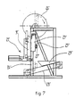
- la figure 7 est une coupe schématique en élévation d'une seconde forme de réalisation, cette vue étant analogue à celle de la fig. 2. Sur la fig. 1, on a représenté une
lame 1 de forme sensiblement rectangulaire allongée, coupée vers la moitié de sa longueur pour mettre en évidence son profil ; lalame 1 est articulée à chacune de ses extrémités sur unsupport 2 dont sont seulement visibles des parties 2', et 2" voisines de l'axe 3 d'articulation de la lame ; l'axe d'articulation 3 est voisin au tranchant 4 de la lame et parallèle à celui-ci ; l'articulation de la lame, dont on décrira plus loin les détails, permet à la lame de pivoter autour de l'axe 3.
- FIG. 1 is a schematic perspective illustration of the essential organs of a device of the invention,
- FIG. 2 is a diagrammatic section in elevation of a particular embodiment of the machine of the invention,
- FIG. 3 is a top view of the same,
- FIG. 4 is a perspective view of a blade support carriage of the machine of the preceding figures,
- FIG. 5 is a partial section in elevation thereof,
- FIG. 6 is a partial plan view of the same, and
- Figure 7 is a schematic sectional elevation of a second embodiment, this view being similar to that of FIG. 2. In fig. 1, there is shown a
blade 1 of substantially rectangular elongated shape, cut around half its length to highlight its profile; theblade 1 is articulated at each of its ends on asupport 2 of which onlyparts 2 'and 2 "are visible, which are close to the axis 3 of articulation of the blade; the axis of articulation 3 is close to the cutting edge 4 of the blade and parallel to it; the articulation of the blade, the details of which will be described below, allows the blade to pivot around axis 3.
La lame 1 est taillée dans une plaque rectangulaire, ou encore parallélépipède aplati, constituée d'un acier approprié ; le tranchant de la lame est constitué par l'arête d'un dièdre formé par des facettes supérieure 5 et inférieure 6 ; la facette 5 a une largeur 1 nettement inférieure à la largeur L de la facette 6 ; le tranchant 4 ou arête du dièdre des facettes est situé légèrement au-dessus du plan médian 7 de la lame ; le plan bissecteur du dièdre, matérialisé par la bissectrice 8, est incliné sur le plan médian 7 de façon à donner aux facettes la disproportion précitée.The
La lame, par l'intermédiaire de son support, est entraînée dans un mouvement alterné de translation en va-et-vient figuré par les flèches 10 ; ce mouvement s'effectue dans un plan, dit plan de chariotage, perpendiculaire au tranchant 4 de la lame ; un tel plan est matérialisé par les traits mixtes 11 ; on a représenté également sur la fig. 1 une pièce de bois 9 en forme de bûche maintenue en position fixe à l'aide de mâchoires telles que 12 faisant prises à chacune de ses extrémités, la bûche est positionnée de telle sorte que sa face inférieure 13 soit située à une distance h au-dessous du plan de chariotage ; le plan de chariotage détermine sur la tranche de la bûche la ligne d'impact du tranchant de la lame et la distance h sera, après fendage, l'épaisseur de la latte de bois constituant l'ébauche d'un bardeau.The blade, by means of its support, is driven in an alternating movement of translation back and forth shown by the
Grâce à sa mobilité en pivotement la lame pourra suivre les fibres du bois qui sont globalement parallèles au plan de translation, ou de chariotage de la lame. Ce caractère pivotant de la lame apparaît être l'une des causes du bon fonctionnement du dispositif de l'invention ; toutefois une condition supplémentaire est requise, à savoir : que l'axe d'articulation 3 de la lame sur son support doit être aussi proche que possible de la ligne 14 d'intersection du plan de la facette 5 et de la face supérieure 15 de la lame ; dans le cas de la figure, l'axe est de façon optimale confondu avec la ligne 14.Thanks to its pivoting mobility, the blade will be able to follow the wood fibers which are generally parallel to the plane of translation, or of turning of the blade. This pivoting nature of the blade appears to be one of the causes of the proper functioning of the device of the invention; however, an additional condition is required, namely: that the axis of articulation 3 of the blade on its support must be as close as possible to the
La lame 1 est maintenue en pivotement entre deux positions de butée, respectivement, une première position de butée inférieure 16 et supérieure 17 ; ces positions de butée sont réglables à l'aide de moyens qui seront décrits plus loin ; la butée 16 est réglée de telle sorte que la facette supérieure 5 du tranchant soit sensiblement parallèle au plan de chariotage qui est dans le cas de la figure un plan horizontal ; dans ce cas particulier, on utilisera le poids en porte-à-faux de la lame par rapport à son axe de pivotement pour servir de sollicitation permanente de la lame vers sa position de butée inférieure. Ainsi avant l'impact du tranchant sur la bûche, le plan de la facette supérieure 5 du tranchant sera approximativement parallèle aux fibres du bois de la bûche 9.The
Sur les fig. 2 et 3, on représente respectivement en élévation et en plan une machine mettant les principes dé fonctionnement décrits avec les figures précédentes. Une telle machine se compose essentiellement d'un châssis 20 supportant des organes 21 de positionnement et de ' maintien des bûches telles que 9, des organes- d'entraînement 22 d'un chariot porte-lame 23 pouvant circuler en va-et-vient dans des longerons supérieurs 24 du châssis, d'un couple de bielles 25 reliant des grandes roues 26 au chariot 23 par l'intermédiaire d'une barre transversale 27, d'un tapis transporteur 28, des lattes de bois fendu et d'une trémie de réception 29 des lattes ; les moyens de positionnement et de maintien des bûches sont constitués par un mât 30 le long duquel peut se déplacer sous l'action d'un vérin 31, un étau 32 de serrage de bûches par un couple de mâchoires antagonistes tel que 12 sous l'action d'un vérin 34; le déplacement vertical de l'étau 32 a lieu pas à pas suivant une commande alogique pneumatique, la hauteur d'un pas correspondant à l'épaisseur h d'une latte. Des moyens d'approvisionnement automatiques en bûches des mâchoires peuvent être prévus. Les organes d'entraînement 22 sont constitués essentiellement d'un moteur 40' de poulies démultipli- catrices 41', 42', de grandes roues 26 et de poulies 43 d'entraînement du tapis.In fig. 2 and 3, there is shown respectively in elevation and in plan a machine putting the operating principles described with the previous figures. Such a machine essentially consists of a
Sur les fig. 4, 5 et 6, on a représenté avec plus de détails le chariot porte-lame. On y remarque tout d'abord qu'il est principalement formé d'un couple de flasques 30 et 31 solidaires de la barre transversale 27 à l'extrémité de laquelle sont articulées les bielles 25. Les faces extérieures des flasques sont pourvues d'un double train de galets 32 destiné à guider le roulement du chariot sur des rails 33 fixés à l'intérieur des longerons supérieurs 24 du châssis ; des galets de centrage 34 montés sur les flasques réalisent le centrage du chariot entre les rails.In fig. 4, 5 and 6, the blade carriage is shown in more detail. First of all, it is noted that it is mainly formed of a pair of
La lame 1 est supportée par les flasques du chariot (analogues aux éléments 2' et 2" de la fig. 1) par l'intermédiaire d'un couple de supports 36 comportant chacun une rainure 37 dans laquelle est engagée la lame à ses extrémités ; chaque support 36 est articulé par l'intermédiaire d'une bague 38 (ou d'un roulement à bille) sur le flasque qui le supporte ; chaque support comporte en outre à l'arrière de la rainure 37 une vis de réglage 39 permettant d'ajuster la position de la lame dans la rainure de telle sorte que la ligne 14 (fig. 1, bord de la facette supérieure) coïncide avec l'axe d'articulation du support sur le flasque ; un tel réglage est nécessaire pour compenser la perte de largeur de la lame après réaffûtage.The
Sur la fig. 5 plus particulièrement, on remarque que les positions de butée supérieure et inférieure précitées sont déterminées au moyen d'une tige filetée 40 solidaire d'un flasque ; les extrémités de la tige 40 sont pourvues d'embouts en caoutchouc tels que 41 ; telle qu'elle est représentée sur la fig. 5, la lame 1 est en position de butée inférieure ; si sous l'effet de l'impact contre la bûche par exemple, la lame 1 venait à pivoter vers le haut, un bras en prolongement 42 solidaire du support 36 viendrait en butée contre l'embout 41 et la lame serait alors en position de butée dite supérieure.In fig. 5 more particularly, it is noted that the abovementioned upper and lower stop positions are determined by means of a threaded
Sur la fig. 7, on a représenté un dispositif analogue à celui des figures précédentes dans lesquelles la lame travaille dans un plan de chariotage vertical. On a affecté aux différents organes de cette machine les numéros de référence affectés aux organes analogues de la machine des figures précédentes ; on remarque que dans ce cas de configuration les bielles 25' poussent le bras 27' en direction de la bûche 9' au lieu de le tirer comme dans le cas précédent. On notera aussi qu'à défaut de la pesanteur la lame est sollicitée en position de butée inférieure par un petit ressort non représenté sur les figures. Bien que l'on ait décrit comment au cours d'un premier impact de la lame contre la bûche cette dernière était fendue le long des fibres du bois, pour donner naissance à une latte, et comment la bûche était translatée parallèlement à elle-même pour présenter une seconde ligne d'impact et donner naissance à une latte suivante, on notera que l'on peut aussi ne commander la translation de la bûche qu'après.plusieurs allers et retours de la lame ; en procédant ainsi dans les cas où la bûche serait noueuse ou les fibres du bois ne seraient pas pour une autre raison sensiblement parallèles à l'axe de la bûche, on effectuera une sorte de rabottage en une ou plusieurs passes, équivalent au travail manuel de dégauchissement pratiqué sur une lamelle ; l'expérience a montré que le dégauchissage, ou rabottage, ainsi pratiqué avec les machines de l'invention est en général suffisant pour procurer des lattes d'épaisseur sensiblement constante et ne pas être préjudiciable à la qualité de celles-ci en vue de constituer des bardeaux.In fig. 7, there is shown a device similar to that of the preceding figures in which the blade works in a vertical planing plane. The different organs of this machine have been assigned the reference numbers assigned to analogous organs of the machine in the preceding figures; we note that in this configuration case the connecting rods 25 'push the arm 27' towards the log 9 'instead of pulling it as in the previous case. It will also be noted that, failing gravity, the blade is biased into the lower stop position by a small spring not shown in the figures. Although it has been described how during a first impact of the blade against the log, the latter was split along the fibers of the wood, to give rise to a slat, and how the log was translated parallel to itself to present a second line of impact and give rise to a next batten, it will be noted that it is also possible to control the translation of the log only after several round trips of the blade; by doing so in cases where the log is knotty or the wood fibers are not for another reason substantially parallel to the axis of the log, we will perform a kind of planing in one or more passes, equivalent to manual work of planing on a coverslip; experience has shown that the planing, or planing, thus practiced with the machines of the invention is generally sufficient to provide slats of substantially constant thickness and not be detrimental to the quality thereof in order to constitute shingles.
On notera enfin que, sans sortir du champ de l'invention selon les revendications, les moyens de déplacement du chariot, au lieu d'être des moyens mécaniques par bielles pourraient être des moyens hydrauliques ou pneumatiques et que les moyens de maintien et d'avancement des bûches pourraient être des moyens mécaniques par exemple par vis ; de façon plus générale, il doit être compris que la présente invention n'est pas limitée aux formes de réalisation ci-dessus décrites ou représentées mais que sa portée est définie par ses caractéristiques générales telles qu'elles ont été énoncées plus haut.Finally, it will be noted that, without departing from the scope of the invention according to the claims, the means for moving the carriage, instead of being mechanical means by connecting rods, could be hydraulic or pneumatic means and that the means for holding and advancement of the logs could be mechanical means, for example by screws; more generally, it should be understood that the present invention is not limited to the embodiments described or shown above but that its scope is defined by its general characteristics as they have been stated above.
Claims (7)
Priority Applications (1)
| Application Number | Priority Date | Filing Date | Title |
|---|---|---|---|
| AT82402097T ATE22034T1 (en) | 1981-11-19 | 1982-11-17 | SHINGLE MAKING MACHINE. |
Applications Claiming Priority (2)
| Application Number | Priority Date | Filing Date | Title |
|---|---|---|---|
| FR8121920 | 1981-11-19 | ||
| FR8121920A FR2516434A1 (en) | 1981-11-19 | 1981-11-19 | MACHINE FOR THE PRODUCTION OF SHINGLES |
Publications (2)
| Publication Number | Publication Date |
|---|---|
| EP0080408A1 EP0080408A1 (en) | 1983-06-01 |
| EP0080408B1 true EP0080408B1 (en) | 1986-09-10 |
Family
ID=9264277
Family Applications (1)
| Application Number | Title | Priority Date | Filing Date |
|---|---|---|---|
| EP82402097A Expired EP0080408B1 (en) | 1981-11-19 | 1982-11-17 | Shingle making machine |
Country Status (4)
| Country | Link |
|---|---|
| EP (1) | EP0080408B1 (en) |
| AT (1) | ATE22034T1 (en) |
| DE (1) | DE3273234D1 (en) |
| FR (1) | FR2516434A1 (en) |
Families Citing this family (4)
| Publication number | Priority date | Publication date | Assignee | Title |
|---|---|---|---|---|
| FR2552700B1 (en) * | 1983-10-04 | 1987-03-20 | Satge Jean | WOOD SHINGLE MACHINE |
| NO155917C (en) * | 1984-08-30 | 1987-06-24 | Halfdan Nilsen | PROCEDURE AND DEVICE FOR CLIFTING FIBER PLATES. |
| GB9617056D0 (en) * | 1996-08-14 | 1996-09-25 | C D R Ltd | Cable drum flange splitting apparatus |
| KR102609453B1 (en) * | 2023-08-10 | 2023-12-01 | 이삼수 | Equipment for manufacturing shingle and method for manufacturing shingle using the same |
Family Cites Families (5)
| Publication number | Priority date | Publication date | Assignee | Title |
|---|---|---|---|---|
| US2183479A (en) * | 1937-07-27 | 1939-12-12 | Elsworth H Jenkins | Shingle making or wood shake cutting machine |
| US2365932A (en) * | 1942-09-29 | 1944-12-26 | Richard E Bierd | Art of splitting shakes and a machine therefor |
| US3224477A (en) * | 1951-10-10 | 1965-12-21 | Joenkoeping Vulcan Ab | Knife structures particularly intended for the peeling of veneer |
| AT179867B (en) * | 1958-07-08 | 1954-10-11 | Hermann Ing Lindner | Rotating log splitter designed to be placed on a drive shaft |
| CA980664A (en) * | 1974-03-26 | 1975-12-30 | Her Majesty In Right Of Canada As Represented By The Minister Of The Dep Artment Of The Environment | Tree cross-cutting blade |
-
1981
- 1981-11-19 FR FR8121920A patent/FR2516434A1/en active Granted
-
1982
- 1982-11-17 AT AT82402097T patent/ATE22034T1/en not_active IP Right Cessation
- 1982-11-17 DE DE8282402097T patent/DE3273234D1/en not_active Expired
- 1982-11-17 EP EP82402097A patent/EP0080408B1/en not_active Expired
Also Published As
| Publication number | Publication date |
|---|---|
| ATE22034T1 (en) | 1986-09-15 |
| FR2516434A1 (en) | 1983-05-20 |
| DE3273234D1 (en) | 1986-10-16 |
| FR2516434B3 (en) | 1984-09-28 |
| EP0080408A1 (en) | 1983-06-01 |
Similar Documents
| Publication | Publication Date | Title |
|---|---|---|
| FR2900361A1 (en) | AUTOMATED SYSTEM FOR SAWING SHORT PIECES OF WOOD | |
| FR2572005A1 (en) | Band saw | |
| EP0270452B1 (en) | Apparatus for cutting out plastic sheets | |
| FR2537040A1 (en) | PROCESS FOR PRODUCING WOOD PARTS WORKING IN ALL SIDES, AND DEVICE FOR IMPLEMENTING SAID METHOD | |
| EP0686450A1 (en) | Cutting apparatus for profiled material e.g. gutters | |
| EP0125175B1 (en) | Apparatus for cutting continuously manufactured cardboard tubes | |
| EP0080408B1 (en) | Shingle making machine | |
| BE1004756A5 (en) | Method for obtaining of lumber from trunk or tree trunk cutting boards, and device for implementing the process. | |
| CA1315189C (en) | Method for feeding fibers to a fiber cutter, and fiber used for this method | |
| FR2528348A1 (en) | Slate cutter with height adjustable disc - has disc on carriage on rails with width adjustable table slot with edging members in folding parallelogram. | |
| FR2524835A1 (en) | METHOD AND APPARATUS FOR EBARBING CUTTING PLATES | |
| EP0322646A1 (en) | Longitudinal wood veneer slicer | |
| EP0418174A1 (en) | Device for dividing elongated pieces of wood into smaller pieces | |
| FR2547762A3 (en) | Thickness-planing machine tool for wood | |
| EP0457659B1 (en) | Method and apparatus for splitting quartered logs of wood to form barrel stares | |
| EP3983161B1 (en) | Cutting machine with a contour saw spiral blade, and its use | |
| FR2696674A1 (en) | Method for making and machining parallel tabs on the two front surfaces of elongated pieces of wood and a two-end profiling machine for carrying out this method. | |
| FR2697463A1 (en) | Wood shaping tool for planks used in constructing chalet - includes cutting wheels mounted on common axis, with guide wheel lying parallel | |
| FR2703286A1 (en) | Method for machining the edges of stone slabs and apparatus implementing same | |
| EP0256957A1 (en) | Numerically-controlled plate shears | |
| FR2503014A1 (en) | Wood loading system for saw mill - has logs positioned and wedged in place by vertical chain controlled by photo-cell | |
| FR2613654A1 (en) | Large logs sawing machine | |
| FR2776217A1 (en) | MACHINING GROUP, PARTICULARLY HACKSAW | |
| FR2855997A1 (en) | INPUT TABLE FOR WOOD SAWING MACHINE | |
| FR2807962A1 (en) | Anti-bounce and retaining tool, for chain saw, comprises slide supported on chain guide with front stud supported on work piece surface |
Legal Events
| Date | Code | Title | Description |
|---|---|---|---|
| PUAI | Public reference made under article 153(3) epc to a published international application that has entered the european phase |
Free format text: ORIGINAL CODE: 0009012 |
|
| AK | Designated contracting states |
Designated state(s): AT BE CH DE FR GB IT LI LU NL SE |
|
| 17P | Request for examination filed |
Effective date: 19831118 |
|
| GRAA | (expected) grant |
Free format text: ORIGINAL CODE: 0009210 |
|
| AK | Designated contracting states |
Kind code of ref document: B1 Designated state(s): AT BE CH DE FR GB IT LI LU NL SE |
|
| PG25 | Lapsed in a contracting state [announced via postgrant information from national office to epo] |
Ref country code: NL Effective date: 19860910 Ref country code: IT Free format text: LAPSE BECAUSE OF FAILURE TO SUBMIT A TRANSLATION OF THE DESCRIPTION OR TO PAY THE FEE WITHIN THE PRESCRIBED TIME-LIMIT;WARNING: LAPSES OF ITALIAN PATENTS WITH EFFECTIVE DATE BEFORE 2007 MAY HAVE OCCURRED AT ANY TIME BEFORE 2007. THE CORRECT EFFECTIVE DATE MAY BE DIFFERENT FROM THE ONE RECORDED. Effective date: 19860910 Ref country code: AT Effective date: 19860910 |
|
| REF | Corresponds to: |
Ref document number: 22034 Country of ref document: AT Date of ref document: 19860915 Kind code of ref document: T |
|
| PG25 | Lapsed in a contracting state [announced via postgrant information from national office to epo] |
Ref country code: SE Effective date: 19860930 |
|
| REF | Corresponds to: |
Ref document number: 3273234 Country of ref document: DE Date of ref document: 19861016 |
|
| PG25 | Lapsed in a contracting state [announced via postgrant information from national office to epo] |
Ref country code: LU Free format text: LAPSE BECAUSE OF NON-PAYMENT OF DUE FEES Effective date: 19861130 Ref country code: LI Effective date: 19861130 Ref country code: CH Effective date: 19861130 Ref country code: BE Effective date: 19861130 |
|
| NLV1 | Nl: lapsed or annulled due to failure to fulfill the requirements of art. 29p and 29m of the patents act | ||
| BERE | Be: lapsed |
Owner name: CLAUX ANTONY Effective date: 19861130 |
|
| PLBE | No opposition filed within time limit |
Free format text: ORIGINAL CODE: 0009261 |
|
| STAA | Information on the status of an ep patent application or granted ep patent |
Free format text: STATUS: NO OPPOSITION FILED WITHIN TIME LIMIT |
|
| GBPC | Gb: european patent ceased through non-payment of renewal fee | ||
| REG | Reference to a national code |
Ref country code: CH Ref legal event code: PL |
|
| PG25 | Lapsed in a contracting state [announced via postgrant information from national office to epo] |
Ref country code: DE Effective date: 19870801 |
|
| 26N | No opposition filed | ||
| REG | Reference to a national code |
Ref country code: FR Ref legal event code: ST |
|
| REG | Reference to a national code |
Ref country code: FR Ref legal event code: RC |
|
| PG25 | Lapsed in a contracting state [announced via postgrant information from national office to epo] |
Ref country code: GB Effective date: 19881122 |
|
| REG | Reference to a national code |
Ref country code: FR Ref legal event code: DA |
|
| PGFP | Annual fee paid to national office [announced via postgrant information from national office to epo] |
Ref country code: FR Payment date: 19891130 Year of fee payment: 8 |
|
| REG | Reference to a national code |
Ref country code: FR Ref legal event code: ST |
|
| REG | Reference to a national code |
Ref country code: FR Ref legal event code: DA |
|
| PG25 | Lapsed in a contracting state [announced via postgrant information from national office to epo] |
Ref country code: FR Free format text: LAPSE BECAUSE OF NON-PAYMENT OF DUE FEES Effective date: 19910731 |
|
| REG | Reference to a national code |
Ref country code: FR Ref legal event code: ST |