EP0080331A2 - Wickelmaschine - Google Patents
Wickelmaschine Download PDFInfo
- Publication number
- EP0080331A2 EP0080331A2 EP82306150A EP82306150A EP0080331A2 EP 0080331 A2 EP0080331 A2 EP 0080331A2 EP 82306150 A EP82306150 A EP 82306150A EP 82306150 A EP82306150 A EP 82306150A EP 0080331 A2 EP0080331 A2 EP 0080331A2
- Authority
- EP
- European Patent Office
- Prior art keywords
- cylinder
- band
- guide
- mounting
- machine
- Prior art date
- Legal status (The legal status is an assumption and is not a legal conclusion. Google has not performed a legal analysis and makes no representation as to the accuracy of the status listed.)
- Withdrawn
Links
Images
Classifications
-
- B—PERFORMING OPERATIONS; TRANSPORTING
- B21—MECHANICAL METAL-WORKING WITHOUT ESSENTIALLY REMOVING MATERIAL; PUNCHING METAL
- B21C—MANUFACTURE OF METAL SHEETS, WIRE, RODS, TUBES, PROFILES OR LIKE SEMI-MANUFACTURED PRODUCTS OTHERWISE THAN BY ROLLING; AUXILIARY OPERATIONS USED IN CONNECTION WITH METAL-WORKING WITHOUT ESSENTIALLY REMOVING MATERIAL
- B21C37/00—Manufacture of metal sheets, rods, wire, tubes, profiles or like semi-manufactured products, not otherwise provided for; Manufacture of tubes of special shape
- B21C37/06—Manufacture of metal sheets, rods, wire, tubes, profiles or like semi-manufactured products, not otherwise provided for; Manufacture of tubes of special shape of tubes or metal hoses; Combined procedures for making tubes, e.g. for making multi-wall tubes
- B21C37/12—Making tubes or metal hoses with helically arranged seams
Definitions
- This invention relates to a machine for winding a metal band helically on to a cylindrical object such as a shaft or a tube.
- the machine finds particular application in the manufacture of mufflers for silencers for internal combustion engines and the invention will therefore be described with reference to such an application, but it will be appreciated that this is not intended to limit the invention in any way.
- Silencers incorporating spiral wound mufflers have been known for a considerable amount of time. It is an object of this invention to provide a machine for the manufacture of, inter alia, such mufflers.
- cylindrical and cylinder are used in their widest sense to denote a generally longitudinally extending object with a section of any fixed curve, normally circular, unless the context indicates otherwise.
- a machine for winding a metal band helically on to a cylinder comprises a rotatable- mounting for the cylinder and a guide for the band, the mounting being adapted to be driven rotationally to draw the band through the guide and helically on to the cylinder after one end thereof has been fastened to the cylinder and the mounting and guide being moveable with respect to one another in the axial direction of the cylinder, to vary the winding pitch.
- the cylinder may conveniently be a metal tube in which case the one end of the band may be fastened to the exterior surface of the tube by welding the end of the ban ⁇ to the tube.
- the mounting comprises a driven spindle and a dead spindle which is capable of being moved axially to allow the mounting of the tube between the spindles both of which are provided with attachment means for the tube.
- the mounting is preferably moveable only in the rotational direction, the guide being moveable axially with respect thereto.
- the guide is mounted on a coarse threaded driving screw, the guide comprising a pair of guide prongs mounted on an internally threaded cube within which the driving screw is freely rotatable.
- the guide prongs are conveniently spaced apart and the ends of the prongs are adapted to receive a tube mounted on the spindles between them and to define a slot extending transversely to the longitudinal axis of the tube. It will be appreciated that rotation of the drive screw will result in the longitudinal displacement of the guide with respect to the tube mounted within the spindles.
- the driven spindle and the drive screw are connected to the same drive means by means of power transmission means, preferably chains.
- the machine is adapted for the manufacture of mufflers for internal combustion engine silencers in which a corrugated band is used
- the machine is adapted to corrugate the band by the addition of a pair of meshing cylinderical gears through which the band may be fed prior to the attachment thereof to the tube.
- At least one of the cylindrical gears is driven, preferably by means of the driving means of the main machine.
- the band or corrugated band is welded on to the surface of the tube while it is being wound thereon.
- the muffler preferably includes a pair of end plates which are welded to the ends of the tube to close the tube.
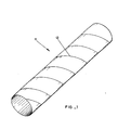
- Reference to Figure 1 shows how a metal band may be formed into a tube 11.
- the edges 13 of the helically formed metal band may butt to the adjacent edge or may overlap the preceeding coil.
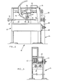
- the machine 10 comprises a winding machine 12 and a corrugating machine 14, the latter being shown in outline in Figure 2 for the sake of clarity.
- the winding machine comprises a rotatable mounting including a driven spindle 16 and a dead spindle 18 which is provided with a screw 20 by means of which the forming cylinder 22 onto which a band is to be welded, can be fastened to the dead spindle 18.
- the driven spindle 16 is fastened to the forming cylinder 22 by means of a shearing pin 24 which is passed through matching holes in the forming tube 22 and the spindle 16.
- the driven spindle 16 is driven by means of a reverseable electric motor 26 the power of which is transmitted to the spindle 16 by means of a chain drive 28.
- a chain drive 30 provides the power for a threaded shaft 32 which is provided with a coarse thread adapted to carry a guide mount 34 with a matching internal thread.
- the guide mount 34 is provided with a pair of guide prongs 36 and 38 which lie respectively under and over the tube 22 when this is mounted between the spindles 16 and 18.
- a roller 40 is located between the prongs 36 and 38 to prevent a band located between the prongs from moving upwardly.
- the corrugating attachment 14 can be seen in Figure 3 comprising a pair of cylindrical gears 42 which are driven by the motor (not shown in Figure 3) through a chain sprocket 44, bevel gears 46 and a chain drive 48, the one gear being driven and the second gear- meshing therewith.
- a band of stainless steel (not shown) is passed between the teeth of the two gears 42 under the urging of the motor through the various power transmission means.
- the corrugated band emerging from the other side of the gears 42 is led to the guide and passed below the roller 40 and between the guide prongs 36 and 38.
- the motor 26 is now stopped to allow the operator to tack the one end of the corrugated band to the surface of the tube forming cylinder 22 whereafter the motor 26 is once again activated so that the corrugated band is drawn through the guide prongs 36 and 38 and wound helically on to the surface of the forming cylinder 22.
- the corrugated band As the corrugated band emerges between the guide prongs, it is welded continuously on to the surface of the tube by the welding gun 39 which is attached to the travelling guide mount 34. It will be appreciated that the pitch of the helical winding will be determined by the pitch of the threads on the threaded shaft 32. It will be appreciated that the corrugations make the metal band more flexible and able to conform to the required helically formed tube.
- the tube is removed from between the spindles 16 and 18, the shearing pin 24 being withdrawn and the cap screw 20 being unscrewed to allow the withdrawal of the dead spindle 18 so that the forming cylinder 22 can drop free.
- End plates of square or any other shape are now welded to the open ends of the tube and the muffler is ready to be installed in a silencer.
- the machine of the invention allows a continuous operation and is therefore eminently suitable for a production line so that spiral wound mufflers of a consistently high quality can be produced more economically than hitherto.
Landscapes
- Engineering & Computer Science (AREA)
- Mechanical Engineering (AREA)
- Exhaust Silencers (AREA)
- Flexible Shafts (AREA)
- Basic Packing Technique (AREA)
- Bending Of Plates, Rods, And Pipes (AREA)
Applications Claiming Priority (2)
| Application Number | Priority Date | Filing Date | Title |
|---|---|---|---|
| ZA818054 | 1981-11-20 | ||
| ZA818054 | 1981-11-20 |
Publications (2)
| Publication Number | Publication Date |
|---|---|
| EP0080331A2 true EP0080331A2 (de) | 1983-06-01 |
| EP0080331A3 EP0080331A3 (de) | 1983-07-20 |
Family
ID=25575773
Family Applications (1)
| Application Number | Title | Priority Date | Filing Date |
|---|---|---|---|
| EP82306150A Withdrawn EP0080331A3 (de) | 1981-11-20 | 1982-11-18 | Wickelmaschine |
Country Status (3)
| Country | Link |
|---|---|
| EP (1) | EP0080331A3 (de) |
| JP (1) | JPS58132319A (de) |
| AU (1) | AU9075782A (de) |
Family Cites Families (4)
| Publication number | Priority date | Publication date | Assignee | Title |
|---|---|---|---|---|
| US1570117A (en) * | 1922-12-30 | 1926-01-19 | Schutte & Koerting Co | Apparatus for applying helical ribs to pipes |
| US2600630A (en) * | 1946-01-22 | 1952-06-17 | Fergusson Hugh Boscawen | Construction of thick-walled high-pressure vessels |
| US3606783A (en) * | 1969-04-01 | 1971-09-21 | Armco Steel Corp | Segmented roll for forming helically corrugated pipe |
| SE427904B (sv) * | 1980-05-05 | 1983-05-24 | Prov & Verktyg Ab | Maskin for kontinuerlig framstellning av skruvlindade ror av platband |
-
1982
- 1982-11-18 EP EP82306150A patent/EP0080331A3/de not_active Withdrawn
- 1982-11-19 JP JP57203523A patent/JPS58132319A/ja active Pending
- 1982-11-19 AU AU90757/82A patent/AU9075782A/en not_active Abandoned
Also Published As
| Publication number | Publication date |
|---|---|
| AU9075782A (en) | 1983-05-26 |
| EP0080331A3 (de) | 1983-07-20 |
| JPS58132319A (ja) | 1983-08-06 |
Similar Documents
| Publication | Publication Date | Title |
|---|---|---|
| DE69616761T2 (de) | Verfahren und vorrichtung zum umreifen von gegenständen | |
| EP2788138B1 (de) | Vorrichtung zum ablängen von wellrohren | |
| DE2645946C2 (de) | Mehrlagiges Wellrohr für Abgasleitungen von Brennkraftmaschinen | |
| EP0336070B1 (de) | Vorrichtung zum Antrieb eines drucksteif geführten Antriebskabels | |
| KR102035250B1 (ko) | 동력전달장치 | |
| EP1084774B1 (de) | Verfahren zur kontinuierlichen Herstellung längsnahtgeschweisster und gewellter Metallrohre und Vorrichtung zur Durchführung des Verfahrens | |
| HK1052667A1 (zh) | 帶有用於主動旋轉內部刀具的驅動機構的用於螺旋方式形成的管的切刀 | |
| US4043161A (en) | Apparatus for forming corrugations of "zero" pitch in coaxial cable | |
| EP0005444A1 (de) | Wickelkopf | |
| EP0080331A2 (de) | Wickelmaschine | |
| DE10126399A1 (de) | Vorrichtung zur kontinuierlichen Herstellung eines schraubenlinienförmig gewellten Metallrohres | |
| DE2804990C2 (de) | Vorrichtung zum kontinuierlichen Wellen dünnwandiger Rohre | |
| EP1184330B1 (de) | Schleppkabelwinde | |
| US3319447A (en) | Method and apparatus for coiling wire | |
| US5957020A (en) | Method and apparatus for perforating corrugated tubing | |
| EP0959988A2 (de) | Wabenkörper mit im inneren eingerahmtem querschnittsbereich, insbesondere für kleinmotoren | |
| US5241848A (en) | Light weight drive shaft | |
| WO1998022264A9 (en) | Method and apparatus for perforating corrugated tubing | |
| DE102010045638B4 (de) | Verfahren zum Ummanteln eines Körpers einer Abgasanlage | |
| DE3116990A1 (de) | Maschine zur herstellung von schraubenfoermig gewickelten blechrohren | |
| SU1754273A1 (ru) | Способ изготовлени из полосы изделий с винтовыми ребрами | |
| DE2539240C3 (de) | Vorrichtung zum Formen und Abziehen einer Reißverschlußschraubenwendel | |
| SU1703306A1 (ru) | Прот жка | |
| DE102011055045B4 (de) | Treibladungsportioniereinrichtung | |
| WO2008047123A1 (en) | Tool and method for forming a thread |
Legal Events
| Date | Code | Title | Description |
|---|---|---|---|
| PUAI | Public reference made under article 153(3) epc to a published international application that has entered the european phase |
Free format text: ORIGINAL CODE: 0009012 |
|
| PUAL | Search report despatched |
Free format text: ORIGINAL CODE: 0009013 |
|
| AK | Designated contracting states |
Designated state(s): AT BE CH DE FR GB IT LI LU NL SE |
|
| AK | Designated contracting states |
Designated state(s): AT BE CH DE FR GB IT LI LU NL SE |
|
| STAA | Information on the status of an ep patent application or granted ep patent |
Free format text: STATUS: THE APPLICATION IS DEEMED TO BE WITHDRAWN |
|
| 18D | Application deemed to be withdrawn |
Effective date: 19840321 |
|
| RIN1 | Information on inventor provided before grant (corrected) |
Inventor name: RYNO, JOHANNES ERASMUS |