EP0079455B1 - Antrieb für elektrische Schienentreibfahrzeuge - Google Patents
Antrieb für elektrische Schienentreibfahrzeuge Download PDFInfo
- Publication number
- EP0079455B1 EP0079455B1 EP82109143A EP82109143A EP0079455B1 EP 0079455 B1 EP0079455 B1 EP 0079455B1 EP 82109143 A EP82109143 A EP 82109143A EP 82109143 A EP82109143 A EP 82109143A EP 0079455 B1 EP0079455 B1 EP 0079455B1
- Authority
- EP
- European Patent Office
- Prior art keywords
- motor
- drive
- pinion
- shaft
- housing
- Prior art date
- Legal status (The legal status is an assumption and is not a legal conclusion. Google has not performed a legal analysis and makes no representation as to the accuracy of the status listed.)
- Expired
Links
- 238000010276 construction Methods 0.000 claims abstract description 8
- 238000004804 winding Methods 0.000 claims abstract description 8
- 230000008878 coupling Effects 0.000 claims description 11
- 238000010168 coupling process Methods 0.000 claims description 11
- 238000005859 coupling reaction Methods 0.000 claims description 11
- 238000006073 displacement reaction Methods 0.000 description 2
- 230000005484 gravity Effects 0.000 description 2
- 230000002146 bilateral effect Effects 0.000 description 1
- 238000010438 heat treatment Methods 0.000 description 1
Images

Classifications
-
- H—ELECTRICITY
- H02—GENERATION; CONVERSION OR DISTRIBUTION OF ELECTRIC POWER
- H02K—DYNAMO-ELECTRIC MACHINES
- H02K7/00—Arrangements for handling mechanical energy structurally associated with dynamo-electric machines, e.g. structural association with mechanical driving motors or auxiliary dynamo-electric machines
- H02K7/10—Structural association with clutches, brakes, gears, pulleys or mechanical starters
- H02K7/116—Structural association with clutches, brakes, gears, pulleys or mechanical starters with gears
-
- H—ELECTRICITY
- H02—GENERATION; CONVERSION OR DISTRIBUTION OF ELECTRIC POWER
- H02K—DYNAMO-ELECTRIC MACHINES
- H02K7/00—Arrangements for handling mechanical energy structurally associated with dynamo-electric machines, e.g. structural association with mechanical driving motors or auxiliary dynamo-electric machines
- H02K7/10—Structural association with clutches, brakes, gears, pulleys or mechanical starters
- H02K7/116—Structural association with clutches, brakes, gears, pulleys or mechanical starters with gears
- H02K7/1163—Structural association with clutches, brakes, gears, pulleys or mechanical starters with gears where at least two gears have non-parallel axes without having orbital motion
Definitions
- the invention relates to a drive for electric rail vehicles with a rotor (rotor winding) on an at least partially hollow motor shaft housing motor which drives a drive axle via an axle gear, the housing of which has a large gear on the drive axle and thus meshing a pinion with a Contains pinion shaft which at least partially protrudes into the motor shaft and is connected to it and is at least at one end in a radial bearing.
- Such a drive is known from AT-B-154719. With him, however, the pinion shaft between the gearbox and the engine is separated by a clutch with Hardy disks.
- the motor is suspended in the bogie or the frame, so that there must be freedom of movement between the gear unit that moves the driving axle and the motor. This is achieved in that the pinion shaft passes through the hollow motor shaft with radial play and is connected to the motor shaft at the other end of the motor by an angularly movable coupling, so that the cardanic deflection is possible. In the case of high-speed engines, there is a risk that the part of the pinion shaft stuck in the engine will flutter.
- the object is achieved in that the housing of the motor and the gear housing are rigidly combined with one another and that the pinion shaft is also located in a radial bearing at the other end and supports the hollow motor shaft over its entire length, these two shafts have a guide bushing with one another and with each other a single drive connection (clamping ring) are detachably connected.
- the object is achieved in a drive of the type mentioned in the case where the motor shaft has a radial bearing on the pinion side, also in that the housing of the motor and the gear housing are rigidly combined with one another, the motor shaft in a bore the other, free end of the Pinion shaft receives and is supported by a guide bush and that the two shafts are releasably connected to each other by a single drive connection (coupling).
- the design according to the invention advantageously results in a long, undivided pinion shaft which can guide and carry the motor shaft on the pinion side, so that at most only three radial bearings are required for the drive motor axle drive unit.
- the number of bearings required is as low as possible, and at the same time a short length is achieved with double motors, which makes it possible, for example, to reduce the center distance of the bogies.
- the guide bushes further improve the guidance of the motor and the pinion shaft and ensure that the motor and pinion shaft behave as a statically determined overall system.
- the motor and gearbox can be dismantled easily and easily by loosening the drive connection and then pulling out the pinion shaft from the hollow shaft. In spite of the compact design of the motor-pinion shaft unit, which is expediently achieved by non-positive connection of the drive connection, both the motor and the axle drive can be exchanged easily and simply.
- the detachable drive connection consists of a coupling, it is possible to design it in a torsionally flexible manner.
- This solution is used in particular when the pinion shaft does not extend the entire length of the hollow motor shaft, but is only guided in one turn of the motor shaft.
- This design is slightly longer than the version with a long pinion shaft that extends through the hollow motor shaft, but has the advantage that torsional elasticity can be achieved via the coupling.
- the non-positive drive connection is advantageously arranged on the side of the drive motor opposite the pinion. The result is a pinion shaft of the greatest possible length.
- the motor-pinion shaft unit is expediently mounted on the side of the pinion in the axle gear housing. This results in the particularly short design according to the invention with a statically determined pinion shaft which has a large bearing distance.
- the traction motor is designed as a double motor. If the traction motor is designed as a double motor, it is possible, according to the known drive, to drive two drive axles simultaneously from one motor housing. According to the invention, a coupling that allows longitudinal displacements can be dispensed with and the overall length can be shortened.
- the drive has an axial bearing, in particular a double-row shoulder bearing for the axial adjustment of the motor-pinion shaft unit.
- the bevel gear pinion can advantageously be set exactly, taking advantage of the fact that a relatively large axial displacement between the stator and the rotor of the motor is possible.
- An arrangement of the axial bearing on the pinion means that the motor pinion shaft unit expands due to heating during operation and the pinion setting advantageously not changed. Expansion takes place only from the pinion bearing in the direction of the second radial bearing, which is designed as a floating bearing.
- the arrangement selected means that a coupling between the motor and the axle drive can be dispensed with without disadvantageous consequences for the operating behavior of the drive according to the invention. Both the correct position of the pinion and the tension-free mounting of the pinion motor shaft unit are always guaranteed.
- the drive motor and drive axles are arranged parallel to one another, the axle gear being designed as an arrow-toothed gear, the gear wheels of which are in particular split.
- the parallel arrangement advantageously creates the possibility for a special arrangement of a motor arrangement parallel to the drive axis with the advantages according to the invention, i.e. without coupling and with only two bearings.
- the split design of the pinion makes it easy to assemble and disassemble.
- the motor-pinion shaft unit is supported in a statically determined manner. It is particularly advantageous that the axial guidance is carried out automatically by the arrow teeth, so that the axial bearing can be omitted. Starting from the center of the arrow teeth, the motor pinion shaft unit can expand freely when heated, so that no axial forces act on the teeth.
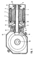
- Fig. 1, 1 denotes the motor housing, which as the housing of a mono drive, but also as half of a bi-motor drive in mono-block construction, as z. B. is particularly suitable for local transport, can be executed.
- the stator winding 2 and the rotor winding 3, which is arranged on the hollow shaft 4, are located in the traction motor 1.
- the hollow shaft 4 surrounds the pinion shaft 5 and is detachably connected to it via the double cone ring 12 at the end opposite the pinion.
- the pinion shaft 5 is statically fixed in the radial bearings 6 and 7 and axially fixed via the axial bearing 8.
- the hollow shaft 4 of the motor 1 is not supported in ball bearings, but is supported on the pinion shaft 5 via the guide bush 9 and the contact point under the double-cone ring, so that it, too, is statically determined on the pinion shaft.
- the bearings 6 and 7 are sealed against the stator and rotor winding by a labyrinth 13 and on the pinion side by a labyrinth in the flange 11.
- the fan 18 is used to cool the motor.
- the drive shaft 16 is directly connected to the bevel gear 15, which is driven by the pinion 14.
- the axle gear housing 17 has a neck 19 which is flanged to the motor housing 1.
- Fig. 2 shows a slightly longer construction, torsionally elastic design, in which an only partially hollow motor shaft is used.
- the motor shaft 20 is mounted in the bearings 21 and 28 and has a bore in its pinion-side part, into which the end 23 of the pinion shaft is inserted and is held guided over the bush 22.
- a coupling 24 is arranged between the motor shaft 20 and the pinion shaft 23 and ensures a torsionally flexible connection between the motor shaft 20 and the pinion shaft 23.
- the bevel gear 29 and the pinion 31 are arranged in the axle gear housing 34, which also has a flange-like neck 33, like the axle gear housing in FIG. 1. However, the neck 33 is longer in order to accommodate the clutch 24.
- a bearing bracket 30 is also inserted in the interior of the axle gear neck 33 and holds an axial bearing 32 and a radial bearing 27 via the cover 26.
- the clutch 24 is connected to the pinion shaft 23 by a screwed bush 25.
- This version can also be designed both as a single motor version with a support in the center of gravity and as a bi-motor version in mono-block construction.
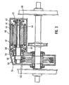
- FIG. 3 which shows the embodiment with the drive motor lying parallel to the drive axis
- 44 designates the pinion shaft, which is also arranged here in the hollow shaft 43 of the rotor winding 42.
- the motor 40 is closed on the outside by a housing which encloses the stator winding 41.
- the bearing on the side opposite the pinion is also closed by a labyrinth of parts 45 and 46.
- the seal is made by the labyrinth 49.
- the motor pinion shaft unit is mounted on the pinion side in the bearing 50, which is arranged in the axle gear outer part 51, and on the opposite side in that by the labyrinth parts 45 and 46 sealed bearings.
- the pinion shaft 44 itself is statically determined at the ends of the two bearings device. It carries on the output side the two-part pinion 52, which meshes with the axle gear 53.
- An axial bearing is not necessary in this embodiment, since the arrow teeth of the pinion 52 and the counter gear 53 provide the axial guidance.
- the hollow shaft solution according to the invention for a drive unit for rail vehicles is particularly suitable for driving axles by three-phase motors.
- other driving motors can also be used without departing from the scope of the invention.
- the advantage of the small size and the small number of bearings always results.
Landscapes
- Engineering & Computer Science (AREA)
- Power Engineering (AREA)
- Connection Of Motors, Electrical Generators, Mechanical Devices, And The Like (AREA)
- Automatic Cycles, And Cycles In General (AREA)
- Electric Propulsion And Braking For Vehicles (AREA)
- Machines For Laying And Maintaining Railways (AREA)
- Escalators And Moving Walkways (AREA)
- Control Of Electric Motors In General (AREA)
- Forklifts And Lifting Vehicles (AREA)
- Train Traffic Observation, Control, And Security (AREA)
Description
- Die Erfindung bezieht sich auf einen Antrieb für elektrische Schienentriebfahrzeuge mit einem den Rotor (Rotorwicklung) auf einer zumindest teilweise hohl ausgebildeten Motorwelle aufweisenden Gehäusemotor, der eine Treibachse über ein Achsgetriebe antreibt, dessen Gehäuse ein grosses Zahnrad auf der Treibachse und damit kämmend ein Ritzel mit einer Ritzelwelle enthält, die zumindest zum Teil in die Motorwelle hineinragt und mit dieser verbunden ist und zumindest am einen Ende in einem Radiallager steckt.
- Aus der AT-B-154719 ist ein derartiger Antrieb bekannt. Bei ihm ist allerdings die Ritzelwelle zwischen dem Getriebe und dem Motor durch eine Kupplung mit Hardy-Scheiben getrennt. Ausserdem ist der Motor in dem Drehgestell oder dem Rahmen aufgehängt, so dass zwischen dem die Bewegungen der Treibachse mitmachenden Getriebe und dem Motor Bewegungsfreiheit vorhanden sein muss. Erreicht wird dies dadurch, dass die Ritzelwelle durch die hohle Motorwelle mit radialem Spiel hindurchlangt und am anderen Ende des Motors durch eine winkelbewegliche Kupplung mit der Motorwelle verbunden ist, so dass die kardanisch ausgelenkt werden kann. Bei schnell laufenden Motoren besteht hier die Gefahr, dass der in dem Motor steckende Teil der Ritzelwelle flattert.
- Es ist Aufgabe der Erfindung, einen Antrieb für elektrische Schienentriebfahrzeuge anzugeben, der es ermöglicht, die Achsen des Fahrzeugs durch Einzelmotoren oder die Hälften eines Doppelmotors derart anzutreiben, dass die Zahl der Wellenlager im Motor-Getriebe-Aggregat bei kurzer Gesamtbaulänge verringert werden kann. Dabei sollen sämtliche Wellen einwandfrei zentriert laufen.
- Die Aufgabe wird dadurch gelöst, dass das Gehäuse des Motors und das Getriebegehäuse miteinander starr vereint sind und dass die RitzelweIle auch am anderen Ende in einem Radiallager steckt und die hohle Motorwelle auf deren gesamter Länge stützt, diese beiden Wellen untereinander eine Führungsbüchse aufweisen und miteinander durch eine einzige Antriebsverbindung (Klemmring) lösbar verbunden sind.
- Die Aufgabe wird bei einem Antrieb der eingangs genannten Art in dem Falle, wenn die Motorwelle ritzelseitig ein Radiallager aufweist, auch dadurch gelöst, dass das Gehäuse des Motors und das Getriebegehäuse miteinander starr vereint sind, die Motorwelle in einer Bohrung das andere, freie Ende der Ritzelwelle aufnimmt und über eine Führungsbüchse stützt und dass die beiden Wellen miteinander durch eine einzige Antriebsverbindung (Kupplung) lösbar verbunden sind.
- Durch die DE-C-2 514 265 ist zwar die starre Verbindung eines Elektromotors mit beidseitigen Winkelgetrieben bekannt. Diese Konstruktion weist aber von der Erfindung abweichende Gattungsmerkmale auf, so dass sie mit ihr im weiteren nicht vergleichbar ist.
- Durch die erfindungsgemässe Ausführung ergibt sich vorteilhaft eine lange, ungeteilte Ritzelwelle, die die Motorwelle auf der Ritzelseite führen und mittragen kann, so dass höchstens nur drei Radiallager für die Fahrmotor-Achsgetriebeeinheit benötigt werden. So ist die Zahl der benötigten Lager so niedrig wie nur möglich, und gleichzeitig wird bei Doppelmotoren eine kurze Baulänge erreicht, die es ermöglicht, zum Beispiel den Achsabstand der Drehgestelle zu verkleinern. Durch die Führungsbüchsen wird ausserdem die Führung der Motor- und der Ritzelwelle weiter verbessert und erreicht, dass sich Motor-und Ritzelwelle als statisch bestimmt gelagertes Gesamtsystem verhalten. Es ergibt sich eine leichte und einfache Demontage von Motor und Getriebe durch Lösen der Antriebsverbindung mit nachfolgendem Herausziehen der Ritzelwelle aus der Hohlwelle. So ist trotz der kompakten Ausbildung der Motor-Ritzelwelleneinheit, die zweckmässig durch Kraftschluss der Antriebsverbindung erreicht wird, ein leichter und einfacher Austausch sowohl des Motors als auch des Achsgetriebes möglich.
- Wenn die lösbare Antriebsverbindung in einer Kupplung besteht, ist es möglich, diese drehelastisch auszubilden. Diese Lösung wird insbesondere dann verwandt, wenn die Ritzelwelle nicht in ganzer Länge durch die hohle Motorwelle hindurchreicht, sondern nur in einer Ausdrehung der Motorwelle geführt ist. Diese Bauform ist etwas länger als die Ausführung mit einer langen Ritzelwelle, die durch die hohle Motorwelle hindurchreicht, besitzt aber den Vorteil, dass über die Kupplung eine Drehelastizität erreicht werden kann. Vorteilhaft ist die kraftschlüssige Antriebsverbindung auf der dem Ritzel gegenüberliegenden Seite des Fahrmotors angeordnet. So ergibt sich eine Ritzelwelle von grösstmöglicher Länge.
- Zweckmässig ist die Motor-Ritzelwelleneinheit auf der Seite des Ritzels im Achsgetriebegehäuse gelagert. So ergibt sich die erfindungsgemäss besonders kurze Bauart mit einer statisch bestimmt gelagerten Ritzelwelle, die einen grossen Lagerabstand aufweist.
- In weiterer Ausgestaltung der Erfindung ist vorgesehen, dass der Fahrmotor als Doppelmotor ausgebildet ist. Bei einer Ausbildung des Fahrmotors als Doppelmotor ist es möglich, entsprechend dem bekannten Antrieb, aus einem Motorgehäuse heraus zwei Treibachsen gleichzeitig anzutreiben. Erfindungsgemäss kann dabei auf eine Längsverschiebungen zulassende Kupplung verzichtet und die Gesamtbaulänge verkürzt werden.
- In weiterer Ausgestaltung der Erfindung ist vorgesehen, dass der Antrieb ein Axiallager, insbesondere ein zweireihiges Schulterlager zur Axialeinstellung der Motor-Ritzelwelleneinheit aufweist. Durch das Axiallager kann das Kegelradritzel vorteilhaft exakt eingestellt werden, wobei ausgenutzt wird, dass eine relativ grosse Axialverschiebung zwischen Ständer und Läufer des Motors möglich ist. Durch eine Anordnung des Axiallagers am Ritzel ergibt sich, dass eine Ausdehnung der Motor-Ritzelwelleneinheit durch Erwärmung im Betrieb die Einstellung des Ritzels vorteilhaft nicht verändert. Eine Ausdehnung erfolgt nur vom Ritzellager aus in Richtung auf das zweite Radiallager, das als Loslager ausgebildet ist. Durch die gewählte Anordnung kann also ohne nachteilige Folgen für das Betriebsverhalten des erfindungsgemässen Antriebs auf eine Kupplung zwischen Motor und Achsgetriebe verzichtet werden. Sowohl die korrekte Lage des Ritzels als auch die verspannungsfreie Lagerung der Ritzel-Motorwelleneinheit sind stets gewährleistet.
- In anderer Ausgestaltung der Erfindung ist vorgesehen, dass Fahrmotor- und Treibachse parallel zueinander angeordnet sind, wobei das Achsgetriebe als pfeilverzahntes Getriebe ausgebildet ist, dessen Zahnräder insbesondere geteilt ausgeführt sind. Durch die Parallelanordnung wird vorteilhaft die Möglichkeit geschaffen, für besondere Einsatzfälle eine Motoranordnung parallel zur Antriebsachse mit den erfindungsgemässen Vorteilen, d.h. ohne Kupplung und mit nur zwei Lagern, vorzusehen. Trotz der Pfeilverzahnung ergibt sich eine gute Montier- und Demontierbarkeit durch die geteilte Ausführung des Ritzels. Auch hier ist die Motor-Ritzelwelleneinheit statisch bestimmt gelagert. Es ist dabei von besonderem Vorteil, dass die Axialführung durch die Pfeilverzahnung selbsttätig erfolgt, so kann das Axiallager entfallen. Ausgehend von der Mitte der Pfeilverzahnung kann sich die Motor-Ritzelwelleneinheit bei Erwärmung frei dehnen, so dass keinerlei Axialkräfte auf die Verzahnung wirken.
- Die Erfindung wird anhand von Zeichnungen näher erläutert, aus denen weitere vorteilhafte Einzelheiten zu entnehmen sind.
- Im einzelnen zeigen im Schnitt:
- Fig. 1 eine Achsgetriebe-Motoreinheit mit durchgehender Ritzelwelle
- Fig.2 2 eine Achsgetriebe-Motoreinheit mit drehelastischer Kupplung und
- Fig. 3 eine Achsgetriebe-Motoreinheit in Parallelanordnung.
- In Fig. 1 bezeichnet 1 das Motorgehäuse, das als Gehäuse eines Monoantriebs, aber ebenso auch als Hälfte eines Bi-Motorantriebs in Mono-blockbauweise, wie er z. B. für den Nahverkehr besonders geeignet ist, ausgeführt sein kann.
- Wenn es sich um einen Bi-Motorantrieb in Monoblockbauweise handelt, ist eine Abstützung nicht erforderlich, da die beiden Seiten des Monoblocks von den Achsgetrieben gehalten werden. Anderenfalls erfolgt eine Abstützung des Motorgehäuses im Schwerpunkt der Achsgetriebe-Motoreinheit, also an der Achsgetriebeseite des Fahrmotors.
- In dem Fahrmotor 1 befinden sich die Ständerwicklung 2 und die Rotorwicklung 3, die auf der Hohlwelle 4 angeordnet ist. Die Hohlwelle 4 umgibt die Ritzelwelle 5 und ist mit dieser über den Doppelkonusring 12 an dem dem Ritzel entgegengesetzten Ende lösbar verbunden. Die Ritzelwelle 5 ist in den Radiallagern 6 und 7 statisch bestimmt gelagert und über das Axiallager 8 axial fest. Die Hohlwelle 4 des Motors 1 ist nicht in Kugellagern gelagert, sondern stützt sich über die Führungsbüchse 9 und die Berührungsstelle unter dem Doppelkonusring auf der Ritzelwelle 5 ab, so dass auch sie auf der Ritzelwelle statisch bestimmt gelagert ist. Die Lager 6 und 7 sind durch ein Labyrinth 13 und auf der Ritzelseite durch ein Labyrinth in dem Flansch 11 gegenüber der Ständer- und Rotorwicklung abgedichtet. Zur Kühlung des Motors dient der Lüfter 18.
- Die Treibachse 16 steht direkt mit dem Kegelrad 15 in Verbindung, das durch das Ritzel 14 angetrieben wird. Zur Aufnahme der Ritzellagerung weist das Achsgetriebegehäuse 17 einen Hals 19 auf, der mit dem Motorgehäuse 1 verflanscht ist. So entsteht eine in bisher unerreichter Weise kompakte Antriebseinheit, die unter Verzicht auf eine Kupplung einen bei allen Beanspruchungen einwandfreien Betrieb gewährleistet.
- Fig. 2 zeigt eine etwas länger bauende drehelastische Ausführung, bei der eine nur teilweise hohle Motorwelle verwendet wird. Die Motorwelle 20 ist in den Lagern 21 und 28 gelagert und weist in ihrem ritzelseitigen Teil eine Bohrung auf, in die das Ende 23 der Ritzelwelle eingeschoben ist und über die Büchse 22 geführt gehalten wird. Zwischen der Motorwelle 20 und der Ritzelwelle 23 ist eine Kupplung 24 angeordnet, die für eine drehelastische Verbindung zwischen Motorwelle 20 und Ritzelwelle 23 sorgt.
- Das Kegelrad 29 und das Ritzel 31 sind in dem Achsgetriebegehäuse 34 angeordnet, das ebenso einen flanschartigen Hals 33 aufweist, wie das Achsgetriebegehäuse in Fig. 1. Der Hals 33 ist jedoch, um die Kupplung 24 unterzubringen, länger ausgebildet. Im Inneren des Achsgetriebehalses 33 ist ebenfalls ein Lagerträger 30 eingeschoben, der über den Deckel 26 ein Axiallager 32 und ein Radiallager 27 hält. Die Kupplung 24 ist mit der Ritzelwelle 23 durch eine aufgeschraubte Büchse 25 verbunden.
- Auch diese Ausführung kann sowohl als Einzelmotorausführung mit einer Abstützung im Schwerpunkt als auch als Bi-Motorausführung in Mono-Blockbauweise ausgebildet sein.
- In Fig. 3, die die Ausführung mit parallel zur Antriebsachse liegendem Fahrmotor zeigt, bezeichnet 44 die Ritzelwelle, die auch hier in der Hohlwelle 43 der Rotorwicklung 42 angeordnet ist. Aussen wird der Motor 40 durch ein Gehäuse abgeschlossen, das die Ständerwicklung 41 umschliesst. Das Lager auf der dem Ritzel entgegengesetzten Seite ist ebenfalls durch ein Labyrinth aus den Teilen 45 und 46 abgeschlossen. Ebenso erfolgt auf der ritzelseitigen Seite vor dem Lüfter 48 die Abdichtung durch das Labyrinth 49. Die Lagerung der Motor-Ritzelwelleneinheit erfolgt auf der Ritzelseite in dem Lager 50, das in dem Achsgetriebeaussenteil 51 angeordnet ist und auf der Gegenseite in dem durch die Labyrinthteile 45 und 46 abgedichteten Lager. Zwischen der Hohlwelle 43 und der Ritzelwelle 44 befindet sich auch hier eine Führungsbüchse 47, die zusammen mit der Auflagestelle unter dem lösbaren Doppelkonusring für eine statisch bestimmte Lagerung des Rotors über die Hohlwelle 43 auf der Ritzelwelle 44 sorgt. Die Ritzelwelle 44 selbst ist in den beiden Lagern an ihren Enden statisch bestimmt gelagert. Sie trägt auf der Abtriebsseite das zweigeteilte Ritzel 52, das mit dem Achsgetrieberad 53 kämmt. Ein Axiallager ist bei dieser Ausführung nicht notwendig, da die Pfeilverzahnung des Ritzels 52 und des Gegenrades 53 für die Axialführung sorgt.
- Die erfindungsgemässe Hohlwellenlösung für eine Antriebseinheit für Schienenfahrzeuge ist besonders für den Antrieb von Achsen durch Drehstrommotore geeignet. Ohne den Rahmen der Erfindung zu verlassen, können jedoch ebenso andere Fahrmotore verwendet werden. Stets ergibt sich der Vorteil der geringen Baugrösse und der geringen Lagerzahl.
Claims (10)
Priority Applications (1)
| Application Number | Priority Date | Filing Date | Title |
|---|---|---|---|
| AT82109143T ATE22373T1 (de) | 1981-11-12 | 1982-10-04 | Antrieb fuer elektrische schienentreibfahrzeuge. |
Applications Claiming Priority (2)
| Application Number | Priority Date | Filing Date | Title |
|---|---|---|---|
| DE3144999 | 1981-11-12 | ||
| DE19813144999 DE3144999A1 (de) | 1981-11-12 | 1981-11-12 | Antrieb fuer elektrische schienentriebfahrzeuge |
Publications (2)
| Publication Number | Publication Date |
|---|---|
| EP0079455A1 EP0079455A1 (de) | 1983-05-25 |
| EP0079455B1 true EP0079455B1 (de) | 1986-09-17 |
Family
ID=6146262
Family Applications (1)
| Application Number | Title | Priority Date | Filing Date |
|---|---|---|---|
| EP82109143A Expired EP0079455B1 (de) | 1981-11-12 | 1982-10-04 | Antrieb für elektrische Schienentreibfahrzeuge |
Country Status (7)
| Country | Link |
|---|---|
| EP (1) | EP0079455B1 (de) |
| JP (1) | JPS5889459A (de) |
| AT (1) | ATE22373T1 (de) |
| BR (1) | BR8206481A (de) |
| CA (1) | CA1213470A (de) |
| DE (2) | DE3144999A1 (de) |
| ES (1) | ES516076A0 (de) |
Families Citing this family (20)
| Publication number | Priority date | Publication date | Assignee | Title |
|---|---|---|---|---|
| DE3515963C2 (de) * | 1985-04-30 | 1986-12-04 | Licentia Gmbh | Integrierter Laengsantrieb |
| DE4015380A1 (de) * | 1990-05-14 | 1991-11-21 | Bergische Stahlindustrie | Zusammengesetztes einzelradfahrwerk fuer schienenfahrzeuge |
| CA2271019A1 (en) * | 1996-11-07 | 1998-05-28 | General Signal Corporation | Transmission assembly |
| AT404016B (de) * | 1997-02-17 | 1998-07-27 | Heraklith Ag | Abdichtungsmaterial |
| DE102006056238A1 (de) * | 2006-11-27 | 2008-05-29 | Graessner Gmbh & Co. Kg The Gear Company | Kurzbauender Servomotor mit Winkelgetriebe |
| DE102007008658A1 (de) * | 2007-02-20 | 2008-08-21 | Flender Industriegetriebe Gmbh & Co. Kg | Kegelradgetriebe, insbesondere Kegelstirnradgetriebe |
| FR2946307B1 (fr) * | 2009-06-05 | 2011-08-05 | Alstom Transport Sa | Bogie moteur de vehicule ferroviaire comprenant un moteur semi-suspendu |
| CN102097889B (zh) * | 2011-02-17 | 2016-07-13 | 国电联合动力技术有限公司 | 一种风力发电机组传动链 |
| DE102012213920A1 (de) * | 2012-08-06 | 2014-02-06 | Voith Patent Gmbh | Getriebebaueinheit und Antriebseinheit mit einer Getriebebaueinheit |
| US8858379B2 (en) * | 2012-09-21 | 2014-10-14 | Arvinmeritor Technology, Llc | Axle assembly having an electric motor module |
| DE102012222273A1 (de) * | 2012-12-05 | 2014-06-05 | Schaeffler Technologies Gmbh & Co. Kg | Antriebsvorrichtung und Ritzelwellenlageranordnung für die Antriebsvorrichtung |
| CN105292138A (zh) * | 2015-11-20 | 2016-02-03 | 南车株洲电力机车有限公司 | 一种大功率机车传动装置 |
| US11247556B2 (en) | 2015-12-17 | 2022-02-15 | Allison Transmission, Inc. | Axle assembly for a vehicle |
| CN109153323B (zh) | 2016-05-06 | 2021-09-10 | 艾里逊变速箱公司 | 具有电动机的车桥总成 |
| USD821930S1 (en) | 2016-06-06 | 2018-07-03 | Axletech International Ip Holdings, Llc | Gearbox assembly for an axle |
| USD883864S1 (en) | 2018-05-10 | 2020-05-12 | Allison Transmission, Inc. | Axle assembly |
| DE102018212041A1 (de) * | 2018-07-19 | 2020-01-23 | Robert Bosch Gmbh | Wischerantrieb und Verfahren zur Montage des Wischerantriebs |
| USD927578S1 (en) | 2018-09-27 | 2021-08-10 | Allison Transmission, Inc. | Axle assembly |
| DE102018218974B3 (de) * | 2018-11-07 | 2019-12-12 | Zf Friedrichshafen Ag | Radsatzgetriebe für ein Schienenfahrzeug |
| CN112572478B (zh) * | 2020-12-30 | 2024-04-16 | 中车资阳机车有限公司 | 一种机车用牵引传动装置 |
Family Cites Families (4)
| Publication number | Priority date | Publication date | Assignee | Title |
|---|---|---|---|---|
| AT154719B (de) * | 1936-05-28 | 1938-10-25 | Bbc Ag Oesterr | Antrieb für elektrisch betriebene Fahrzeuge, insbesondere für Schienenfahrzeuge leichter Bauart und Straßenfahrzeuge. |
| AT254257B (de) * | 1965-01-27 | 1967-05-10 | Wiener Starkstromwerke Gmbh | Einzelachsantrieb für elektrische Triebfahrzeuge |
| DE1965816A1 (de) * | 1969-12-23 | 1971-07-01 | Siemens Ag | Antrieb fuer elektrische Triebfahrzeuge |
| DE2514265C3 (de) * | 1975-03-27 | 1979-06-13 | Siemens Ag, 1000 Berlin Und 8000 Muenchen | Antrieb für ein elektrisches Schienenfahrzeug |
-
1981
- 1981-11-12 DE DE19813144999 patent/DE3144999A1/de not_active Withdrawn
-
1982
- 1982-09-29 ES ES516076A patent/ES516076A0/es active Granted
- 1982-10-04 AT AT82109143T patent/ATE22373T1/de not_active IP Right Cessation
- 1982-10-04 DE DE8282109143T patent/DE3273365D1/de not_active Expired
- 1982-10-04 EP EP82109143A patent/EP0079455B1/de not_active Expired
- 1982-11-08 CA CA000415049A patent/CA1213470A/en not_active Expired
- 1982-11-09 BR BR8206481A patent/BR8206481A/pt unknown
- 1982-11-10 JP JP57196140A patent/JPS5889459A/ja active Pending
Also Published As
| Publication number | Publication date |
|---|---|
| ES8306346A1 (es) | 1983-06-01 |
| BR8206481A (pt) | 1983-09-27 |
| CA1213470A (en) | 1986-11-04 |
| EP0079455A1 (de) | 1983-05-25 |
| JPS5889459A (ja) | 1983-05-27 |
| DE3144999A1 (de) | 1983-05-19 |
| ATE22373T1 (de) | 1986-10-15 |
| ES516076A0 (es) | 1983-06-01 |
| DE3273365D1 (en) | 1986-10-23 |
Similar Documents
| Publication | Publication Date | Title |
|---|---|---|
| EP0079455A1 (de) | Antrieb für elektrische Schienentreibfahrzeuge | |
| EP0617214B1 (de) | Achsversetztes Winkelgetriebe | |
| EP1940667B1 (de) | Kardanische doppelgelenkkupplung für schienenfahrzeuge | |
| EP0712753B1 (de) | Wechselgetriebe für Kraftfahrzeuge mit einer vorn eingebauten, querliegenden Antriebseinheit | |
| EP0758602B1 (de) | Einzelachsantrieb elektrischer Triebfahrzeuge | |
| DE102012216298A1 (de) | Winkelgetriebe | |
| DE3707176C2 (de) | ||
| EP0043340B1 (de) | Schienengebundenes elektrisches Triebfahrzeug | |
| DE102011086020A1 (de) | Getriebeeinheit | |
| EP0052244B1 (de) | Drehgestell für Schienenfahrzeuge, wie Strassenbahnen | |
| DE2616310C3 (de) | Antrieb für ein elektrisches Schienenfahrzeug | |
| DE2548058C2 (de) | Doppelachsantrieb für Schienenfahrzeuge | |
| EP0077290B1 (de) | Doppelachslängsantrieb für ein elektrisches Schienenfahrzeug | |
| DE962709C (de) | Gelenkwellenantrieb, insbesondere fuer elektrische Triebfahrzeuge | |
| EP0085022B1 (de) | Triebaggregat für die Treibachsen von Schienenfahrzeugen | |
| DE2644414B2 (de) | Antrieb für ein elektrisches Schienenfahrzeug | |
| AT132606B (de) | Zahnradgetriebe. | |
| DE383781C (de) | Drehgestell fuer durch Rotationsmotoren angetriebene Lokomotiven | |
| DE698915C (de) | Triebwerk fuer Schienenfahrzeuge, insbesondere durch Brennkraftmaschinen angetriebene Triebwagen | |
| EP0054134A1 (de) | Doppelachsantrieb für Schienenfahrzeuge | |
| DE3631974A1 (de) | Vorrichtung zum antrieb eines schubrostkuehlers | |
| DE822093C (de) | Durch einen Elektromotor ueber ein Zahnraederpaar angetriebene Treibachse von Lokomotiven oder Triebwagen | |
| DE1575395A1 (de) | Verbesserung an Wellen umlaufender Maschinen | |
| AT56784B (de) | Antriebsvorrichtung für Luftfahrzeuge. | |
| DE1121938B (de) | Riemenscheibenantrieb fuer ein sowohl fuer Strassen- als auch fuer Gelaendebetrieb geeignetes Kraftfahrzeug, insbesondere fuer landwirtschaftliche Zwecke |
Legal Events
| Date | Code | Title | Description |
|---|---|---|---|
| PUAI | Public reference made under article 153(3) epc to a published international application that has entered the european phase |
Free format text: ORIGINAL CODE: 0009012 |
|
| 17P | Request for examination filed |
Effective date: 19821012 |
|
| AK | Designated contracting states |
Designated state(s): AT BE CH DE FR GB IT LI NL SE |
|
| GRAA | (expected) grant |
Free format text: ORIGINAL CODE: 0009210 |
|
| AK | Designated contracting states |
Kind code of ref document: B1 Designated state(s): AT BE CH DE FR GB IT LI NL SE |
|
| REF | Corresponds to: |
Ref document number: 22373 Country of ref document: AT Date of ref document: 19861015 Kind code of ref document: T |
|
| REF | Corresponds to: |
Ref document number: 3273365 Country of ref document: DE Date of ref document: 19861023 |
|
| PGFP | Annual fee paid to national office [announced via postgrant information from national office to epo] |
Ref country code: AT Payment date: 19861029 Year of fee payment: 5 |
|
| ITF | It: translation for a ep patent filed | ||
| ET | Fr: translation filed | ||
| PLBI | Opposition filed |
Free format text: ORIGINAL CODE: 0009260 |
|
| 26 | Opposition filed |
Opponent name: AEG AKTIENGESELLSCHAFT, BERLIN UND FRANKFURT Effective date: 19870617 |
|
| NLR1 | Nl: opposition has been filed with the epo |
Opponent name: AEG AKTIENGESELLSCHAFT, |
|
| PGFP | Annual fee paid to national office [announced via postgrant information from national office to epo] |
Ref country code: NL Payment date: 19871031 Year of fee payment: 6 |
|
| PLBM | Termination of opposition procedure: date of legal effect published |
Free format text: ORIGINAL CODE: 0009276 |
|
| STAA | Information on the status of an ep patent application or granted ep patent |
Free format text: STATUS: OPPOSITION PROCEDURE CLOSED |
|
| 27C | Opposition proceedings terminated |
Effective date: 19880122 |
|
| PG25 | Lapsed in a contracting state [announced via postgrant information from national office to epo] |
Ref country code: GB Effective date: 19891004 Ref country code: AT Effective date: 19891004 |
|
| PG25 | Lapsed in a contracting state [announced via postgrant information from national office to epo] |
Ref country code: SE Effective date: 19891005 |
|
| ITTA | It: last paid annual fee | ||
| PG25 | Lapsed in a contracting state [announced via postgrant information from national office to epo] |
Ref country code: LI Effective date: 19891031 Ref country code: CH Effective date: 19891031 Ref country code: BE Effective date: 19891031 |
|
| BERE | Be: lapsed |
Owner name: THYSSEN INDUSTRIE A.G. Effective date: 19891031 |
|
| PG25 | Lapsed in a contracting state [announced via postgrant information from national office to epo] |
Ref country code: NL Effective date: 19900501 |
|
| GBPC | Gb: european patent ceased through non-payment of renewal fee | ||
| NLV4 | Nl: lapsed or anulled due to non-payment of the annual fee | ||
| PG25 | Lapsed in a contracting state [announced via postgrant information from national office to epo] |
Ref country code: FR Effective date: 19900629 |
|
| REG | Reference to a national code |
Ref country code: CH Ref legal event code: PL |
|
| REG | Reference to a national code |
Ref country code: FR Ref legal event code: ST |
|
| EUG | Se: european patent has lapsed |
Ref document number: 82109143.6 Effective date: 19900705 |
|
| PGFP | Annual fee paid to national office [announced via postgrant information from national office to epo] |
Ref country code: DE Payment date: 19951214 Year of fee payment: 14 |
|
| PG25 | Lapsed in a contracting state [announced via postgrant information from national office to epo] |
Ref country code: DE Effective date: 19970701 |