EP0079201A2 - Lecteurs de bande - Google Patents
Lecteurs de bande Download PDFInfo
- Publication number
- EP0079201A2 EP0079201A2 EP82305857A EP82305857A EP0079201A2 EP 0079201 A2 EP0079201 A2 EP 0079201A2 EP 82305857 A EP82305857 A EP 82305857A EP 82305857 A EP82305857 A EP 82305857A EP 0079201 A2 EP0079201 A2 EP 0079201A2
- Authority
- EP
- European Patent Office
- Prior art keywords
- pair
- reel
- moving member
- moving
- rotating
- Prior art date
- Legal status (The legal status is an assumption and is not a legal conclusion. Google has not performed a legal analysis and makes no representation as to the accuracy of the status listed.)
- Granted
Links
Images


Classifications
-
- G—PHYSICS
- G11—INFORMATION STORAGE
- G11B—INFORMATION STORAGE BASED ON RELATIVE MOVEMENT BETWEEN RECORD CARRIER AND TRANSDUCER
- G11B15/00—Driving, starting or stopping record carriers of filamentary or web form; Driving both such record carriers and heads; Guiding such record carriers or containers therefor; Control thereof; Control of operating function
- G11B15/18—Driving; Starting; Stopping; Arrangements for control or regulation thereof
- G11B15/26—Driving record carriers by members acting directly or indirectly thereon
- G11B15/32—Driving record carriers by members acting directly or indirectly thereon through the reels or cores on to which the record carrier is wound
-
- G—PHYSICS
- G11—INFORMATION STORAGE
- G11B—INFORMATION STORAGE BASED ON RELATIVE MOVEMENT BETWEEN RECORD CARRIER AND TRANSDUCER
- G11B15/00—Driving, starting or stopping record carriers of filamentary or web form; Driving both such record carriers and heads; Guiding such record carriers or containers therefor; Control thereof; Control of operating function
- G11B15/02—Control of operating function, e.g. switching from recording to reproducing
- G11B15/10—Manually-operated control; Solenoid-operated control
-
- G—PHYSICS
- G11—INFORMATION STORAGE
- G11B—INFORMATION STORAGE BASED ON RELATIVE MOVEMENT BETWEEN RECORD CARRIER AND TRANSDUCER
- G11B15/00—Driving, starting or stopping record carriers of filamentary or web form; Driving both such record carriers and heads; Guiding such record carriers or containers therefor; Control thereof; Control of operating function
- G11B15/18—Driving; Starting; Stopping; Arrangements for control or regulation thereof
- G11B15/44—Speed-changing arrangements; Reversing arrangements; Drive transfer means therefor
Definitions
- tuner pack which is formed by accommodating a tuner circuit portion, which carries out the reception, tuning, detection and amplification of the radio waves, in a casing of approximately the same shape as the tape cartridge, and fitting this tuner pack in the tape player, in place of a tape cartridge.
- an object of the present invention to provide a tape player which is of simple construction.
- Another object of the present invention is to provide a tape player which is improved as regards its operative ability.
- a still further object of the invention is to provide a tape player of which the size is effectively made small.
- apparatus for controlling movement of a tape disposed on at least one reel, the reel defining a hole therethrough, the apparatus comprising: a moving member adapted for co-operation with the said hole for rotating the said reel, the member being both rotatable about an axis and slidable along this axis; means for rapidly rotating the said moving member; means for slowly rotating the said moving member; first means for coupling the said moving member and the said rapid rotating means when the said moving member is slid in a first direction; and second means for coupling the said moving member and the said slow rotating means when the said moving member is slid in a second direction.
- apparatus for controlling movement of tape disposed on a pair of reels, each of the reels defining a hole therethrough
- the apparatus comprising: a pair of moving members, adapted for co-operation with respective ones of the said holes for rotating the said reels, the said members being rotatable about first and second axis respectively, and slidable along the said first and second axes respectively; a pair of means for rotating the said pair of moving members respectively, in opposite directions, and a pair of coupling means, one of the said coupling means being for coupling one of the said pair of moving members and a corresponding one of the said pair of rotating means when one of the said moving members is slid in one direction, and the other of the said coupling means being for coupling the other of the said pair of moving members and the other of the said pair of rotating means when another of the said moving members is slid in one direction.
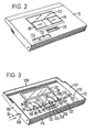
- a casing or cabinet 11 is formed approximately the same size as seen in its front view as a cartridge case, for example a cassette case, which holds a tape cassette.
- a cartridge case for example a cassette case, which holds a tape cassette.
- One planar surface of cabinet 11 forms a lid 12 for covering a tape cassette loaded in cabinet 11.
- Lid 12 is supported in such a way that it is able to be opened and closed by being rotated in the directions of arrows A and B in Figure 1b by a hand of the user.
- Lid 12 is slightly locked in both the open and closed positions, so that it does not rattle.
- Lid 12 is provided with a cassette holder which will be described in detail later.
- a fast forward operating element 19 and a rewind operating element 20 are arranged at positions corresponding to reel shafts 17 and 18 (which become take-up reels during fast forward and rewind operations) on lid 12, so as to include rotary shafts 171, 181 of reel shafts 17, 18.
- Fast forward and rewind operating elements 19, 20 are arranged so as to be capable of depressing rotary shafts 171, 181, to be described later, of reel shafts 17, 18 in their axial directions.
- Both ends of support shaft 24 are supported by bearing parts 197, 207 formed on the underside of lid 12.
- fast forward and rewind operating elements 19, 20 are rotationally biased outwards from lid 12 about support shaft 24 by means of leaf springs 198, 208, respective ends of which are supported on support shaft 24, and the other ends of which press against the central portions of fast forward and rewind operating elements 19, 20.
- these portions are checked by abutment elements (not shown) which are formed on peripheries of the through-holes of lid 12 through which fast forward and rewind operating elements 19, 20 are inserted, and the edges of fast forward and rewind operating elements 19, 20.
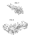
- Head chassis 31 is biased for rotation in the direction of the arrow D in Figure 6 about shaft 311, by means of a torsion spring (not shown), one end of which abuts the side of head chassis 31, and the other end of which is abutted by cassette holder 28, the torsion spring being wound around shaft 311.
- Pinch lever 301 is biased for rotation in the direction of the arrow C in the figure about shaft 311 by means of a coil spring (not shown), which extends between pinch lever 301 and head chassis 31.
- a shaft 302 of pinch roller 30 is arranged to extend so that shaft 302 freely fits into a slot 312 formed in head chassis 31.
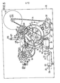
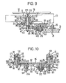
- Gearwheel 42 is in mesh with gearwheel 35 of flywheel 33, and gearwheel 43 is in mesh with gearwheel 41 of reel shaft 17. Gearwheel 42 is then in a position in which gearwheel 42 would mesh with gearwheel 40 on reel shaft 17, but there is a vertical gap between these gearwheels 42, 40 as seen in Figure 9, so that these gearwheels 42, 40 fail to mesh with each other.
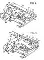
- a shaft 254 is provided on main chassis 25 approximately midway between reel shaft 18 and shaft 252.
- a bearing member 51 of approximately cylindrical shape is provided on shaft 254 in such a way that bearing member 51 is freely rotatable and also freely slidable along the direction of shaft 254, i.e., in the vertical direction in Figure 10.
- a rewind lever 52 and a gearwheel 53 are fitted on to bearing member 51.
- a coil spring 512 is provided between the lower end in Figure 10 of bearing member 51 and a washer 511, which is fitted on to the lower part in the figure of shaft 254. Bearing member 51 is thus biased upwards in the figure, and in this condition gearwheel 53 meshes with gearwheel 50 of reel shaft 18.
- leaf switch 56 is put in the ON condition, and reel shaft 17 is locked in its depressed, i.e. operated, position. with this depression of reel shaft 17, rotary shaft 171 is also then lowered downwards in the figure, and gearwheels 40, 41, which are mounted on rotary shaft 171, are also shifted in the same direction.
- gearwheel 41 comes out of mesh with gearwheel 43
- gearwheel 40 comes into mesh with gearwheel 42.
- the turning force of flywheel 33 in the anti-clockwise direction in Figure 6 is transmitted to reel cap 38 through gearwheels 35, 42, and 40 and rotary shaft 171.
- Reel cap 38 is therefore rotated at high speed in the anti-clockwise direction in Figure 6, so that fast forward operation of the tape occurs.
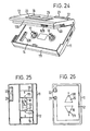
- stop operating element 22 is supported on cassette holder 28, so that stop operating element 22 is freely slidable in the vertical direction in Figure 13.
- stop operating element 22 is supported on cassette holder 28 in such a way that stop operating element 22 is prevented from sliding off upwards in Figure 13.
- Operating shaft 221 extends downwards in Figure 13 from the undersurface in the figure of stop operating element 22, and coil spring 222 is mounted on the lower end in the figure of operating shaft 221. This is then mounted on the base surface of drive portion 223 having an approximately conical shape.
- First abutment portion 541 of locking lever 54 is here pressed against taper portion 224 of drive portion 223, by means of the biasing force of spring 545 (see Figure 6).
- stop operating element 22 is biased upwards in Figure 13 by means of spring 222 towards the position in which further upward movement is restricted.
- the tape player explained in this embodiment is provided with an automatic stop mechanism whereby the tape player is automatically brought into a stopped condition when the tape reaches its end during a play back condition.
- an end portion of friction lever 58 is provided in the lower portion of gearwheel 43 in Figure 9, with a well-known type of friction mechanism arranged between them.
- friction lever 58 is biased towards the direction of rotation.
- Slot 581 is formed at the other end of friction lever 58, and projecting pin 591 is freely fitted into one end portion of detection lever 59 in slot 581.
- Detection lever 59 is freely rotatably supported at about its middle by shaft 592 which projects from main chassis 25.
- stop slider 57 As explained earlier, is supported on main chassis 25 in such a way that stop slider 57 is freely slidable in the directions of the arrow in the figure. Stop slider 57 is normally held in the intermediate position shown in Figure 14a by means of torsion spring 577 shown in Figure 6. Thus, projections 578, 579 formed at-opposite ends of stop slider 57 are positioned at the lower part in Figure 14a of taper portions 372, 472 of locking members 37, 47 of reel shafts 17, 18.
- reel shaft 18 is pressed downwards in the figure and as explained earlier is locked in the depressed position by means of third abutment portion 543 of locking lever 54.
- taper portion 472 of locking member 47 of reel shaft 18 is pressed against projection 579 of stop slider 57, so that stop slider 57 is slid to the right in Figure 14b against the biasing force of torsion spring 577.
- Projection 572 of stop slider 57 is then positioned approximately contacting bearing member 36 of reel shaft 17, and projection 578 is interposed between flange portion 361 of bearing member 36 and abutment portion 373 of locking member 37.
- Projection 579 of stop slider 57 is then positioned in between flange portion 461 of bearing member 46 of reel shaft 18 and stop portion 473 of locking member 47. Consequently, even if an attempt is made to operate rewind operating element 20 in the fast forward condition, stop portion 473 of locking member 47 of reel shaft 18 contacts projection 579 of stop slider 57, preventing operating element 20 from being pressed into its normal depressed position.
- a high space factor is able to be achieved with a very simple construction and assembly is able to be facilitated by the formation of through-hole 128 in the side portion of lid 12, introducing support shaft 24 into lid 12 through through-hole 128, by simply providing bearing portions 191 to 197 and 201 to 207 with through-holes through which support shaft 24 is able to be inserted.
- through-holes 128, 129 are formed in both of side portions 125, 127 of lid 12, a through- holde could of course be formed in one side only.
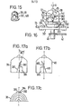
- Figure 15 shows the configuration of reel caps 38, 48 of reel shafts 17, 18.
- Blades 381, 481 of approximately diamond-shape in side view are formed on the outer surface of approximately cylindrical reel caps 38, 48.
- Blades 381, 481 are able to abut with projections of reel hubs of tape cassettes for the purpose of transmitting the turning force of reel caps 38, 48 to the reel hubs.
- the projections (in the case of an ordinary compact tape cassette, six such projections for each reel hub) project in respective peripherally inwards directions from reel hubs.
- the operation of blade 381 of reel cap 38, for example, will be explained with reference to Figure 16 (the operation of blade 481 the same as that of reel cap 38, so an explanation of blade 481 is omitted).
- blades 381, 481 of reel caps 38, 48 are shown in Figures 17a to 17c.
- Figures 17a, 17c show the shape of reel cap 38
- Figure 17b shows the shape of reel cap 48.
- the explanation will be mainly directed to reel cap 38.
- blade 381 of reel cap 38 projects with an inclination such that it is approximately tangential to the peripheral side face of reel cap 38.
- This projecting face comprises a perpendicaular portion 384 formed parallel to the centre line of reel cap 38, and in approximately its upper half in Figure 17a, inclined portion 382 having an angle with respect to the centre line.
- Reel cap 48 is formed with perpendicular portion 484 and inclined portion 482, similar to perpendicular portion 384 and inclined portion 382 of reel cap 38, but directed oppositely to the corresponding portions on reel cap 38.
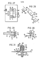
- first drive portion 212 which is integral with playback operating element 21, is shifted in the direction such as to separate from first abutment portion 541 of locking lever 54, i.e. in the direction of arrow I in the Figure 22, thereby returning playback operating element 21 to the non- operated position.
- Figures 25 and 26 show embodiments of the tape player described above of different external appearance and shape. Parts which are the same as those described above are given the same reference numerals and a detailed explanation thereof is omitted.
- the position where both reel shafts 17, 18 are regulated means a shallow position where both locking members 37, 47 are not locked together with second and third abutment portions 542, 543 of locking lever 54.
- both reel shafts 17, 18 are not locked at the operative position even if stop operating element 22 is operated.
- the operative stroke of stop operating element 22 is short in comparison with the case where fast forward and rewind operating elements 19, 20 are operated alone.
- Figure 29 shows a case wherein a pause operating member 70 is mounted using one opening of through-hole 71 which is one of a pair of through-holes of a tape cassette designed for capstans of tape players capable of passing therethrough.
- a pause operating member 70 is mounted using one opening of through-hole 71 which is one of a pair of through-holes of a tape cassette designed for capstans of tape players capable of passing therethrough.
- tape cassette 13 is mounted to tape cassette holding portion 14 (see Figure 1b)
- capstan 26 is passed through the other of the pair of through-holes for capstans (which is not shown in the figure but is the same as through hole 71 of Figure 29)
- pause operating member 70 is passed through hole 71 which is one of the holes for capstans.
- Pause operating member 70 is supported in such a way as to be slidable along through-hole 71, and is connected to a well known push-pull mechanism at the lower portion in the figure of main chassis 25 and,at the same time, is in engagement with a leaf switch 72.
- a pause operating element 73 in lid 12 in the same way as the other operating elements 19, 20, and the like. If pause operating element 73 is once operated in such a manner as to be pressed, pause operating member 70 is pressed downwards in the figure and locked in position.
- the operating elements are passed through various kinds of openings or through-holes (the through-holes through which capstan 26 is passed, the through-holes through which guide pins are passed and the through-holes through which reel shafts 17, 18 are passed) which are formed in the direction of the thickness of tape cassette 13, so as to make it possible to operate from the side of the planar portion of tape cassette 13, it is not necessary to especially provide the spaces for putting the operating elements within cabinet 11, which is advantageous in view of the use of the space and which will fully contribute to, in particular, making small the size of the tape player.
Landscapes
- Casings For Electric Apparatus (AREA)
- Unwinding Webs (AREA)
Applications Claiming Priority (6)
| Application Number | Priority Date | Filing Date | Title |
|---|---|---|---|
| JP56178164A JPS5880152A (ja) | 1981-11-06 | 1981-11-06 | テ−プレコ−ダ装置 |
| JP178164/81 | 1981-11-06 | ||
| JP37744/82 | 1982-03-10 | ||
| JP57037744A JPS58155564A (ja) | 1982-03-10 | 1982-03-10 | カセットテ−プレコ−ダ装置 |
| JP82673/82 | 1982-05-17 | ||
| JP57082673A JPS58199464A (ja) | 1982-05-17 | 1982-05-17 | カセットテ−プレコ−ダ装置 |
Publications (3)
| Publication Number | Publication Date |
|---|---|
| EP0079201A2 true EP0079201A2 (fr) | 1983-05-18 |
| EP0079201A3 EP0079201A3 (en) | 1983-07-20 |
| EP0079201B1 EP0079201B1 (fr) | 1988-01-27 |
Family
ID=27289569
Family Applications (1)
| Application Number | Title | Priority Date | Filing Date |
|---|---|---|---|
| EP82305857A Expired EP0079201B1 (fr) | 1981-11-06 | 1982-11-04 | Lecteurs de bande |
Country Status (6)
| Country | Link |
|---|---|
| US (2) | US4587583A (fr) |
| EP (1) | EP0079201B1 (fr) |
| BR (1) | BR8206451A (fr) |
| CA (1) | CA1206258A (fr) |
| DE (1) | DE3278053D1 (fr) |
| HK (1) | HK28189A (fr) |
Cited By (1)
| Publication number | Priority date | Publication date | Assignee | Title |
|---|---|---|---|---|
| EP0455548A2 (fr) * | 1990-04-30 | 1991-11-06 | Goldstar Co. Ltd. | Dispositif d'entraînement de bobines d'un enregistreur à cassette vidéo |
Families Citing this family (5)
| Publication number | Priority date | Publication date | Assignee | Title |
|---|---|---|---|---|
| JPS6028057A (ja) * | 1983-07-27 | 1985-02-13 | Sony Corp | テ−プレコ−ダ |
| KR920001009Y1 (ko) * | 1989-08-07 | 1992-02-08 | 다나신덴기 가부시끼가이샤 | 테이프 레코더 |
| JP2925848B2 (ja) * | 1992-07-10 | 1999-07-28 | タナシン電機株式会社 | 回転伝達装置 |
| TW245792B (fr) * | 1993-06-10 | 1995-04-21 | Ibm | |
| JPH10222975A (ja) * | 1997-02-07 | 1998-08-21 | Sony Corp | ラジオ受信機付き記録及び/又は再生装置 |
Citations (6)
| Publication number | Priority date | Publication date | Assignee | Title |
|---|---|---|---|---|
| GB723407A (en) * | 1951-12-31 | 1955-02-09 | Ursula Kuerzeder | A device for conveying the tape of magnetic recorders |
| DE1085344B (de) * | 1954-04-20 | 1960-07-14 | Walter Instr Ltd | Magnettongeraet |
| US3601333A (en) * | 1969-02-19 | 1971-08-24 | Mohawk Data Sciences Corp | Tape-reeling system having tape tension control |
| DE2003907A1 (de) * | 1970-01-29 | 1971-11-04 | Sued Atlas Werke Gmbh | Magnettonbandgeraet,insbesondere Kassettenkleinstgeraet mit umspulbaren Bandtraegerspulen |
| DE2221251A1 (de) * | 1972-03-10 | 1973-09-13 | Naehma Ag Unteraegeri | Vorrichtung zur automatischen repetition an einem bandspeichergeraet und verfahren zu ihrem betrieb |
| US3912195A (en) * | 1973-01-19 | 1975-10-14 | Sony Corp | Tape transport device for tape recording and/or reproducing apparatus |
Family Cites Families (4)
| Publication number | Priority date | Publication date | Assignee | Title |
|---|---|---|---|---|
| NL7006246A (fr) * | 1970-04-29 | 1971-11-02 | ||
| US4342058A (en) * | 1979-04-20 | 1982-07-27 | Olympus Optical Co., Ltd. | Apparatus for running magnetic tapes |
| JPS56140932A (en) * | 1980-04-07 | 1981-11-04 | Toray Ind Inc | Isolation of cyclohexene by adsorption |
| JPS56140933A (en) * | 1980-04-07 | 1981-11-04 | Sumitomo Chem Co Ltd | Preparation of cymene |
-
1982
- 1982-11-01 US US06/438,352 patent/US4587583A/en not_active Expired - Fee Related
- 1982-11-04 EP EP82305857A patent/EP0079201B1/fr not_active Expired
- 1982-11-04 DE DE8282305857T patent/DE3278053D1/de not_active Expired
- 1982-11-05 CA CA000414978A patent/CA1206258A/fr not_active Expired
- 1982-11-05 BR BR8206451A patent/BR8206451A/pt not_active IP Right Cessation
-
1985
- 1985-12-02 US US06/803,728 patent/US4669006A/en not_active Expired - Fee Related
-
1989
- 1989-04-06 HK HK281/89A patent/HK28189A/xx not_active IP Right Cessation
Patent Citations (6)
| Publication number | Priority date | Publication date | Assignee | Title |
|---|---|---|---|---|
| GB723407A (en) * | 1951-12-31 | 1955-02-09 | Ursula Kuerzeder | A device for conveying the tape of magnetic recorders |
| DE1085344B (de) * | 1954-04-20 | 1960-07-14 | Walter Instr Ltd | Magnettongeraet |
| US3601333A (en) * | 1969-02-19 | 1971-08-24 | Mohawk Data Sciences Corp | Tape-reeling system having tape tension control |
| DE2003907A1 (de) * | 1970-01-29 | 1971-11-04 | Sued Atlas Werke Gmbh | Magnettonbandgeraet,insbesondere Kassettenkleinstgeraet mit umspulbaren Bandtraegerspulen |
| DE2221251A1 (de) * | 1972-03-10 | 1973-09-13 | Naehma Ag Unteraegeri | Vorrichtung zur automatischen repetition an einem bandspeichergeraet und verfahren zu ihrem betrieb |
| US3912195A (en) * | 1973-01-19 | 1975-10-14 | Sony Corp | Tape transport device for tape recording and/or reproducing apparatus |
Cited By (2)
| Publication number | Priority date | Publication date | Assignee | Title |
|---|---|---|---|---|
| EP0455548A2 (fr) * | 1990-04-30 | 1991-11-06 | Goldstar Co. Ltd. | Dispositif d'entraînement de bobines d'un enregistreur à cassette vidéo |
| EP0455548A3 (fr) * | 1990-04-30 | 1994-05-04 | Gold Star Co |
Also Published As
| Publication number | Publication date |
|---|---|
| US4669006A (en) | 1987-05-26 |
| CA1206258A (fr) | 1986-06-17 |
| BR8206451A (pt) | 1983-09-27 |
| US4587583A (en) | 1986-05-06 |
| EP0079201A3 (en) | 1983-07-20 |
| HK28189A (en) | 1989-04-14 |
| EP0079201B1 (fr) | 1988-01-27 |
| DE3278053D1 (en) | 1988-03-03 |
Similar Documents
| Publication | Publication Date | Title |
|---|---|---|
| JPH08130789A (ja) | 記録再生装置 | |
| EP0079201A2 (fr) | Lecteurs de bande | |
| US5764433A (en) | Short-side-loading tape cassette recording and/or reproducing apparatus | |
| EP0105746B1 (fr) | Lecteur de cassette | |
| US4206488A (en) | Miniature cassette tape recorder | |
| JPH0545479A (ja) | 携帯用電子機器 | |
| JPS634313Y2 (fr) | ||
| EP0191361B1 (fr) | Lecteur de cassette et mécanisme d'entraînement de bande magnétique | |
| EP0116458B1 (fr) | Lecteur de cassette avec récepteur de radio | |
| KR860000917B1 (ko) | 카세트 테이프 레코오더 장치 | |
| JPS628853B2 (fr) | ||
| JPS626595Y2 (fr) | ||
| US6636373B1 (en) | Tape running drive device and tape recording and or reproducing device | |
| JPS626596Y2 (fr) | ||
| JPS626597Y2 (fr) | ||
| KR870000516B1 (ko) | 카세트 테이프 레코오더 장치 | |
| KR860000222B1 (ko) | 테이프 플레이어 | |
| JPS628856B2 (fr) | ||
| JP3736009B2 (ja) | 記録及び/又は再生装置 | |
| JPS642282Y2 (fr) | ||
| JPS6224862B2 (fr) | ||
| JPS6048815B2 (ja) | 手動操作装置 | |
| JPH08116180A (ja) | 携帯用電子機器 | |
| JPS5994270A (ja) | カセツトテ−プレコ−ダ装置 | |
| JPS6224864B2 (fr) |
Legal Events
| Date | Code | Title | Description |
|---|---|---|---|
| PUAI | Public reference made under article 153(3) epc to a published international application that has entered the european phase |
Free format text: ORIGINAL CODE: 0009012 |
|
| 17P | Request for examination filed |
Effective date: 19821124 |
|
| AK | Designated contracting states |
Designated state(s): DE FR GB NL |
|
| PUAL | Search report despatched |
Free format text: ORIGINAL CODE: 0009013 |
|
| AK | Designated contracting states |
Designated state(s): DE FR GB NL |
|
| RAP1 | Party data changed (applicant data changed or rights of an application transferred) |
Owner name: KABUSHIKI KAISHA TOSHIBA |
|
| GRAA | (expected) grant |
Free format text: ORIGINAL CODE: 0009210 |
|
| AK | Designated contracting states |
Kind code of ref document: B1 Designated state(s): DE FR GB NL |
|
| REF | Corresponds to: |
Ref document number: 3278053 Country of ref document: DE Date of ref document: 19880303 |
|
| ET | Fr: translation filed | ||
| PLBE | No opposition filed within time limit |
Free format text: ORIGINAL CODE: 0009261 |
|
| STAA | Information on the status of an ep patent application or granted ep patent |
Free format text: STATUS: NO OPPOSITION FILED WITHIN TIME LIMIT |
|
| 26N | No opposition filed | ||
| PGFP | Annual fee paid to national office [announced via postgrant information from national office to epo] |
Ref country code: GB Payment date: 19961028 Year of fee payment: 15 |
|
| PGFP | Annual fee paid to national office [announced via postgrant information from national office to epo] |
Ref country code: DE Payment date: 19961108 Year of fee payment: 15 |
|
| PGFP | Annual fee paid to national office [announced via postgrant information from national office to epo] |
Ref country code: FR Payment date: 19961111 Year of fee payment: 15 |
|
| PGFP | Annual fee paid to national office [announced via postgrant information from national office to epo] |
Ref country code: NL Payment date: 19961128 Year of fee payment: 15 |
|
| PG25 | Lapsed in a contracting state [announced via postgrant information from national office to epo] |
Ref country code: GB Free format text: LAPSE BECAUSE OF NON-PAYMENT OF DUE FEES Effective date: 19971104 |
|
| PG25 | Lapsed in a contracting state [announced via postgrant information from national office to epo] |
Ref country code: FR Free format text: THE PATENT HAS BEEN ANNULLED BY A DECISION OF A NATIONAL AUTHORITY Effective date: 19971130 |
|
| PG25 | Lapsed in a contracting state [announced via postgrant information from national office to epo] |
Ref country code: NL Free format text: LAPSE BECAUSE OF NON-PAYMENT OF DUE FEES Effective date: 19980601 |
|
| GBPC | Gb: european patent ceased through non-payment of renewal fee |
Effective date: 19971104 |
|
| PG25 | Lapsed in a contracting state [announced via postgrant information from national office to epo] |
Ref country code: DE Free format text: LAPSE BECAUSE OF NON-PAYMENT OF DUE FEES Effective date: 19980801 |
|
| NLV4 | Nl: lapsed or anulled due to non-payment of the annual fee |
Effective date: 19980601 |
|
| REG | Reference to a national code |
Ref country code: FR Ref legal event code: ST |