EP0077247A1 - Procédé et installation de fabrication de pièces métalliques par moulage en sable ou analogue - Google Patents
Procédé et installation de fabrication de pièces métalliques par moulage en sable ou analogue Download PDFInfo
- Publication number
- EP0077247A1 EP0077247A1 EP82401791A EP82401791A EP0077247A1 EP 0077247 A1 EP0077247 A1 EP 0077247A1 EP 82401791 A EP82401791 A EP 82401791A EP 82401791 A EP82401791 A EP 82401791A EP 0077247 A1 EP0077247 A1 EP 0077247A1
- Authority
- EP
- European Patent Office
- Prior art keywords
- metal parts
- manufacturing metal
- molding
- forming walls
- forming
- Prior art date
- Legal status (The legal status is an assumption and is not a legal conclusion. Google has not performed a legal analysis and makes no representation as to the accuracy of the status listed.)
- Withdrawn
Links
- 239000002184 metal Substances 0.000 title claims abstract description 37
- 239000004576 sand Substances 0.000 title claims abstract description 33
- 238000005266 casting Methods 0.000 title claims abstract description 5
- 238000004519 manufacturing process Methods 0.000 title claims description 34
- 238000000034 method Methods 0.000 title description 8
- 238000007664 blowing Methods 0.000 claims abstract description 4
- 238000001816 cooling Methods 0.000 claims description 28
- 238000000465 moulding Methods 0.000 claims description 26
- CURLTUGMZLYLDI-UHFFFAOYSA-N Carbon dioxide Chemical compound O=C=O CURLTUGMZLYLDI-UHFFFAOYSA-N 0.000 claims description 25
- 239000007789 gas Substances 0.000 claims description 23
- IJGRMHOSHXDMSA-UHFFFAOYSA-N Atomic nitrogen Chemical compound N#N IJGRMHOSHXDMSA-UHFFFAOYSA-N 0.000 claims description 19
- 239000002826 coolant Substances 0.000 claims description 18
- 239000003507 refrigerant Substances 0.000 claims description 18
- 239000012778 molding material Substances 0.000 claims description 17
- XLYOFNOQVPJJNP-UHFFFAOYSA-N water Substances O XLYOFNOQVPJJNP-UHFFFAOYSA-N 0.000 claims description 16
- 238000005057 refrigeration Methods 0.000 claims description 15
- 238000009434 installation Methods 0.000 claims description 14
- 229910002092 carbon dioxide Inorganic materials 0.000 claims description 12
- 239000001569 carbon dioxide Substances 0.000 claims description 12
- 239000007788 liquid Substances 0.000 claims description 12
- 239000002245 particle Substances 0.000 claims description 10
- 238000012546 transfer Methods 0.000 claims description 9
- 229910052757 nitrogen Inorganic materials 0.000 claims description 8
- 239000000463 material Substances 0.000 claims description 7
- 239000012809 cooling fluid Substances 0.000 claims description 4
- 239000011236 particulate material Substances 0.000 claims description 4
- 238000005507 spraying Methods 0.000 claims description 4
- 238000009826 distribution Methods 0.000 claims description 3
- 239000007787 solid Substances 0.000 claims description 3
- 229910052799 carbon Inorganic materials 0.000 claims description 2
- 239000003595 mist Substances 0.000 claims description 2
- 239000000843 powder Substances 0.000 claims 2
- OKTJSMMVPCPJKN-UHFFFAOYSA-N Carbon Chemical compound [C] OKTJSMMVPCPJKN-UHFFFAOYSA-N 0.000 claims 1
- PNEYBMLMFCGWSK-UHFFFAOYSA-N aluminium oxide Inorganic materials [O-2].[O-2].[O-2].[Al+3].[Al+3] PNEYBMLMFCGWSK-UHFFFAOYSA-N 0.000 claims 1
- 235000011089 carbon dioxide Nutrition 0.000 claims 1
- 238000001914 filtration Methods 0.000 claims 1
- 239000000203 mixture Substances 0.000 claims 1
- 239000011148 porous material Substances 0.000 claims 1
- 238000007711 solidification Methods 0.000 claims 1
- 230000008023 solidification Effects 0.000 claims 1
- 239000012530 fluid Substances 0.000 abstract description 3
- 238000010304 firing Methods 0.000 description 14
- 241001508691 Martes zibellina Species 0.000 description 13
- 230000000295 complement effect Effects 0.000 description 5
- 230000015572 biosynthetic process Effects 0.000 description 4
- 230000008929 regeneration Effects 0.000 description 3
- 238000011069 regeneration method Methods 0.000 description 3
- 238000010583 slow cooling Methods 0.000 description 3
- 239000007921 spray Substances 0.000 description 3
- 239000000126 substance Substances 0.000 description 3
- 239000002131 composite material Substances 0.000 description 2
- 235000021183 entrée Nutrition 0.000 description 2
- 238000010438 heat treatment Methods 0.000 description 2
- 239000012528 membrane Substances 0.000 description 2
- 239000000047 product Substances 0.000 description 2
- 238000004064 recycling Methods 0.000 description 2
- 229920005989 resin Polymers 0.000 description 2
- 239000011347 resin Substances 0.000 description 2
- 238000003860 storage Methods 0.000 description 2
- 238000013519 translation Methods 0.000 description 2
- BPQQTUXANYXVAA-UHFFFAOYSA-N Orthosilicate Chemical compound [O-][Si]([O-])([O-])[O-] BPQQTUXANYXVAA-UHFFFAOYSA-N 0.000 description 1
- 230000033228 biological regulation Effects 0.000 description 1
- 230000001276 controlling effect Effects 0.000 description 1
- 230000007423 decrease Effects 0.000 description 1
- 230000003247 decreasing effect Effects 0.000 description 1
- 238000010586 diagram Methods 0.000 description 1
- 229910001873 dinitrogen Inorganic materials 0.000 description 1
- 230000000694 effects Effects 0.000 description 1
- 239000008246 gaseous mixture Substances 0.000 description 1
- 238000000265 homogenisation Methods 0.000 description 1
- 239000012263 liquid product Substances 0.000 description 1
- 230000014759 maintenance of location Effects 0.000 description 1
- 238000012986 modification Methods 0.000 description 1
- 230000004048 modification Effects 0.000 description 1
- 239000003110 molding sand Substances 0.000 description 1
- JCXJVPUVTGWSNB-UHFFFAOYSA-N nitrogen dioxide Inorganic materials O=[N]=O JCXJVPUVTGWSNB-UHFFFAOYSA-N 0.000 description 1
- 238000002360 preparation method Methods 0.000 description 1
- 230000001105 regulatory effect Effects 0.000 description 1
- 239000000523 sample Substances 0.000 description 1
- 238000012360 testing method Methods 0.000 description 1
- 238000009834 vaporization Methods 0.000 description 1
- 230000008016 vaporization Effects 0.000 description 1
- 238000004804 winding Methods 0.000 description 1
Images


Classifications
-
- B—PERFORMING OPERATIONS; TRANSPORTING
- B22—CASTING; POWDER METALLURGY
- B22C—FOUNDRY MOULDING
- B22C9/00—Moulds or cores; Moulding processes
- B22C9/12—Treating moulds or cores, e.g. drying, hardening
- B22C9/126—Hardening by freezing
Definitions
- the present invention relates to the manufacture of metal parts by molding, of the type in which one develops, by using forming walls such as chassis and model, and from a molding material consisting of humidified particles, a structure rigid intended to serve either as a mold receiving the molten metal, or as cores intended to be placed in such a mold.
- a structure rigid intended to serve either as a mold receiving the molten metal, or as cores intended to be placed in such a mold.
- more or less moistened sand is used as particles, to which are added products capable of ensuring, during the molding operation, the rigidity of the shaped structure, these products generally being chemicals, such as desiccated silicate or resins.
- the preparation of such composite structures is relatively complex, therefore costly, and moreover has drawbacks during unhooking which consists in reducing again into particles the rigid structure temporarily created for molding and which is recycled for a new operation.
- the subject of the present invention is a manufacturing process which is simple and inexpensive to implement, which eliminates any pollution of the environment, which ensures an extremely simple stripping operation and which suppresses the regeneration of the particulate material after molding, while ensuring correct mechanical strength of the particle structure.
- the invention is part of this observation, which is known per se, that the rigidity of a structure of humidified particles can be ensured by cooling to a temperature much lower than setting in ice using a refrigerant which can be, for for example, liquid nitrogen during vaporization or any other suitable fluid. It has been proposed to produce such molds by spraying the surface of the mold with a spray of liquid nitrogen or by passing the molds shaped into a frame inside a low temperature refrigeration tunnel.
- the humidification of the molding material is carried out before its introduction between the forming walls where cooling is provided.
- the molding material in the insufficiently humidified state is previously cooled before its introduction between the forming walls and humidification is ensured by a homogeneous distribution of water in the material during its transfer to said forming walls.
- the cooling of the structure occurs first by solid conduction between the forming walls in the cooled state and the materials of the structure, then, if necessary, the temperature specified above is reached by adding a regularly distributed coolant. in the mass of said structure.
- This last operation can be carried out by circulation of a transit coolant through said structure, advantageously by blowing a coolant but the regularly distributed coolant can also be made up of coolant particles, for example nitrogen at the state of mist or spray, or carbon dioxide snow, intimately mixed with the molding material, just before formation of the structure to be stiffened and advantageously, during the transfer operation to the forming walls.
- the invention also relates to an installation for implementing the above method.
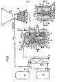
- a molding installation essentially comprises a device for developing a sand structure 1, a device for supplying sand 2, or firing head, a head for refrigeration 3.
- the device for developing a sand structure 1 essentially comprises a chassis-housing 4 formed from side walls 11, a bottom 12 and a wall-cover 13, the assembly being divided in the median plane into two half complementary parts 18 and 19 separated from each other by a model plate 14, essentially consisting of a central support plate 15 and two half-models 16 and 17, the juxtaposition, face against face, in l absence of the support plate 15 represents the shape of the part to be molded.
- These two half-parts 18 and 19 are carried by piston rods 20 and 21.
- the housing is thermally insulated at 22.
- the cover plate 13 is equipped with inlet passages 23 and 24 which are intended to come opposite with clearances 25, 26, respectively formed in a bottom plate 27 of the firing head 2, the seal between the firing head 2 and the device 1 then being provided by seals 28.
- This firing head 2 is adapted to move, with spacing or approximation according to the arrows f 1 , f 2 relative to the device 1 on the one hand and, on the other hand, in translation according to the arrows f 3 and f 4 to come below a hopper sand loading 28.
- the bottom wall 12 is equipped with outlet passages 29, 30, with a sand stop grid.
- the refrigeration head 3 consists of a wall 31 insulated at 32 with a recess 33, the radial extension of which is such that it covers the passages 23 and 24 of the device 1, as shown in the drawings and the seal is also ensured here by a seal 34.
- the recess 33 of this refrigeration head 3 communicates by a conduit 36 and a flexible tube 37 with an outlet 38 d an exchanger 39, an inlet 40 of which is supplied via a pipe 41 with refrigeration gas from a reservoir 42, this refrigeration gas possibly being, for example, compressed air or nitrogen gas.
- the exchanger 39 is cooled by a winding 43 connected by a thermostatic valve 44 to a liquid nitrogen tank 45.
- FIG. 2 it can be seen that the invention is applied to an installation of the same kind as that of FIG. 1, except that it is a question here of forming rigid structures 50 intended to constitute mold cores and no longer mold walls, these cores 50 then being placed in a manner known per se in mold frames which have been produced according to the technique described with reference to FIG. 1, or according to any other previously known technique.
- the invention is also applied to the formation of two half-molds 61 and 62 obtained here again by the presence of a model plate 63, held inside a chassis 64 in which the inlet passages for sand and coolant 65 and 66 can still be recognized here.
- a model plate 63 held inside a chassis 64 in which the inlet passages for sand and coolant 65 and 66 can still be recognized here.
- the main outlet passages for the coolant 67 and 68 which are fitted with filters 69 and 70 adapted to retain the sand, but also, additional inlet passages 71 and 72 have been provided which are connected to the same source of refrigerant gas as the main passages 65 and 66.
- FIG. 3 shows additional outlets at the most inaccessible place of the model in the form of a ring 73 connected: to an inner pipe 75 towards an outlet 76. This ensures local diversion along f 4 , f ′ 4 of the flow of refrigerant gas, precisely in the most inaccessible angle of the model.
- FIG. 5 it can be seen here that, for the formation of two complementary half-molds of the same type as those encountered in the preceding figures, there is here a model plate which is made wholly or partly in porous wall 90, this hollow model being connected at its upper end to an outlet 91, while refrigerant gas inlet passages are formed at different points of the frame at 92, 93, 94, 95, 96, 97, so to create currents which are indicated by the arrows extending all around the model 90.
- the refrigerating fluid thus passes regularly, in a uniform way, through the porous wall of the model and escapes by the exit 91 to the atmosphere.
- FIG. 6 represents the same model structure as that represented in FIG. 5, with the essential difference that the model plate 100 produced in porous wall, is here connected at its upper end to an inlet passage 101 of refrigerated gas, which passes uniformly through the porous wall 102 constituting this model 100 to flow into the mass of sand, before escaping to the lower outlet passages 103, 104 and upper 105 and 106.
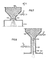
- a firing head 120 contains sand previously moistened and the cooling by the supply of a cooling fluid is ensured by a nozzle 121 formed in a transfer duct 122 and connected to a source of cooling fluid which can be of liquid nitrogen or carbon dioxide under pressure which will be expanded during its distribution in the grains of sand being transferred to the forming walls 123.
- the grains of sand in the firing head 130 are in the insufficiently humidified state and a rehumidification by spraying is carried out in a transfer duct 131 between firing head 130 and forming walls 133. of water by means of a nozzle 134, then cooling by spraying a cooling fluid by means of a nozzle 135.
- FIG. 9 represents a model 140 intended to be inserted into forming walls, as has been represented in FIG. 1.
- the model 140 comprises a metal plate 141 having protrusions such as 142 which are complementary and represent the shape of the object to be manufactured, and protrusions such as 143 forming a source pouring duct.
- the plate 141 is pierced with a plurality of channels 144, leading to clearances 145 closed two by two by studs 146 so as to form a continuous duct 147, for a refrigerant admitted at 148 and withdrawn at 149.
- the plate- support 141 is advantageously trivialized, that is to say that the parts of the model 142 are removable and therefore changed from one manufacture to another without modification of the support plate itself, which forms a heat exchanger for cooling the sand surrounding by simple thermal conduction.
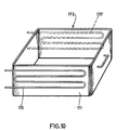
- cooling frames by simple thermal conduction, and in this case, as shown in FIG. 10, it suffices to provide cooling coils 170, 170 ′, in thermal contact externally against certain forming walls. 171 of a chassis 172.
- FIG. 11 shows schematically the adap tion of the invention to a conventional molding line so as to increase its productivity.
- a conventional chain 150 comprises a firing head 151 and forming walls 152, 153, intended to make a structure of molding sand 154, and the various structures 154a, 154b, 154c, 154d, are pushed in a train, so as to form between two structures, for example 154c and 154d, a molding cavity 155.
- a cryogenic chain 160 has been arranged which comprises, as described with reference to FIG.
- the refrigeration device 164 is supplied with refrigerant by a pipe 167 provided with an exchanger 168, in which the coolant is cooled by liquid nitrogen coming from a tank 169.
- the cryogenic sand structures 165 are stored in a waiting tunnel 170 for keeping cold, before t to be transferred by a device 171 to the main chain 150, where they are inserted between the molding structures 154, at the rate of one structure 165 for three structures 154, which makes it possible to improve productivity by 30% .
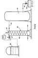
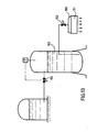
- a cooling head 180 for the sand placed in a molding frame 181 is supplied via the valve 182 with air at -78 ° C at 7 bars withdrawn from a buffer tank 183 charged with air in 184 cooled in an exchanger 185 by heat exchange with carbon dioxide flowing in passages 186, this cold carbon dioxide resulting from the expansion by the valve 187 of a gas stream from a liquid carbon dioxide tank 188 at -20 ° C under a pressure of 20 bars.
- Temperature regulation is ensured by a thermal probe 189 controlling the opening or closing of the valve relaxation 187.
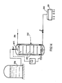
- a gassing head 190 of a molding frame 191 is directly supplied with carbon dioxide at -50 ° C. under a pressure of 7 bars from a storage tank 193, through a valve 192, so that the gas is further cooled, this carbon dioxide at -50 ° C resulting from expansion through a valve 194 of liquid carbon dioxide at -20 ° C at 20 bars.
- a gassing head 200 of a molding frame 201 a gaseous mixture at -78 ° C of air and carbon dioxide from a cooling mixer tank 202 with baffles 203, supplied with a portion of air under pressure of 7 bars in 204 and in liquid carbon dioxide sprayed in 205 from a storage tank 206 of liquid carbon dioxide at -20 ° C. under 20 bars.
- a circulation turbine 207 cooperates with the baffles 203 to ensure the homogenization of the refrigerated composite gas thus formed.
- sand molded test pieces were prepared which were cooled to gradually decreasing temperatures from -10 ° C to a value close to -120 ° C to -140 ° C and we noted each time the flexural strength R in kg-cm2.
- Curves A and B were obtained with sand having a water content of 4% and 6% respectively with simple conduction cooling, while curves C and D were also obtained with sand having a water content of 4 % and 6t respectively, but with gas cooling.
Landscapes
- Engineering & Computer Science (AREA)
- Mechanical Engineering (AREA)
- Manufacture Of Alloys Or Alloy Compounds (AREA)
Applications Claiming Priority (2)
| Application Number | Priority Date | Filing Date | Title |
|---|---|---|---|
| FR8119038 | 1981-10-09 | ||
| FR8119038A FR2514274A1 (fr) | 1981-10-09 | 1981-10-09 | Procede et installation de fabrication de pieces metalliques par moulage en sable ou analogue |
Publications (1)
| Publication Number | Publication Date |
|---|---|
| EP0077247A1 true EP0077247A1 (fr) | 1983-04-20 |
Family
ID=9262892
Family Applications (1)
| Application Number | Title | Priority Date | Filing Date |
|---|---|---|---|
| EP82401791A Withdrawn EP0077247A1 (fr) | 1981-10-09 | 1982-10-01 | Procédé et installation de fabrication de pièces métalliques par moulage en sable ou analogue |
Country Status (4)
| Country | Link |
|---|---|
| EP (1) | EP0077247A1 (OSRAM) |
| JP (1) | JPS5874243A (OSRAM) |
| CA (1) | CA1209780A (OSRAM) |
| FR (1) | FR2514274A1 (OSRAM) |
Cited By (3)
| Publication number | Priority date | Publication date | Assignee | Title |
|---|---|---|---|---|
| FR2566687A1 (fr) * | 1984-06-27 | 1986-01-03 | Air Liquide | Dispositif de fabrication de moules ou de noyaux de moulage congeles |
| WO1997001407A1 (en) * | 1995-06-24 | 1997-01-16 | Air Products And Chemicals, Inc. | Method for forming a mould for use in casting and mould formed by said method |
| KR20240068656A (ko) * | 2022-11-04 | 2024-05-17 | 난징 유니버시티 오브 에어로노틱스 앤드 애스트로노틱스 | 내부 미세다공을 이용한 냉동 사형의 여러 경로를 통한 고효율 냉동방법 및 장치 |
Families Citing this family (2)
| Publication number | Priority date | Publication date | Assignee | Title |
|---|---|---|---|---|
| JP5958892B2 (ja) * | 2012-01-23 | 2016-08-02 | 国立研究開発法人産業技術総合研究所 | 凍結中子の製造方法及びそれに用いられる中子造型用型枠 |
| CN112077262A (zh) * | 2020-09-03 | 2020-12-15 | 北京机科国创轻量化科学研究院有限公司 | 一种冷冻复合铸型3d打印成形方法及装置 |
Citations (4)
| Publication number | Priority date | Publication date | Assignee | Title |
|---|---|---|---|---|
| CA447141A (en) * | 1948-03-09 | Forbes Blackwood Peter | Casting apparatus | |
| GB1537471A (en) * | 1975-08-14 | 1978-12-29 | Booth & Co Ltd W H | Foundry mould production |
| DE2909839A1 (de) * | 1979-03-13 | 1980-09-25 | Linde Ag | Verfahren zum herstellen einer giessform |
| FR2454859A1 (fr) * | 1979-04-28 | 1980-11-21 | Inst Odlewnictwa | Procede de durcissement des moules et noyaux de fonderie par voie de congelation des composants liquides du sable |
Family Cites Families (3)
| Publication number | Priority date | Publication date | Assignee | Title |
|---|---|---|---|---|
| JPS5584249A (en) * | 1978-12-16 | 1980-06-25 | Nippon Sanso Kk | Production of mold |
| JPS566754A (en) * | 1979-06-27 | 1981-01-23 | Kubota Ltd | Freezing method of refrigerating mold |
| JPS56128640A (en) * | 1980-03-13 | 1981-10-08 | Sintokogio Ltd | Molding method of green sand mold |
-
1981
- 1981-10-09 FR FR8119038A patent/FR2514274A1/fr active Granted
-
1982
- 1982-09-30 CA CA000412620A patent/CA1209780A/fr not_active Expired
- 1982-10-01 EP EP82401791A patent/EP0077247A1/fr not_active Withdrawn
- 1982-10-09 JP JP17701182A patent/JPS5874243A/ja active Pending
Patent Citations (4)
| Publication number | Priority date | Publication date | Assignee | Title |
|---|---|---|---|---|
| CA447141A (en) * | 1948-03-09 | Forbes Blackwood Peter | Casting apparatus | |
| GB1537471A (en) * | 1975-08-14 | 1978-12-29 | Booth & Co Ltd W H | Foundry mould production |
| DE2909839A1 (de) * | 1979-03-13 | 1980-09-25 | Linde Ag | Verfahren zum herstellen einer giessform |
| FR2454859A1 (fr) * | 1979-04-28 | 1980-11-21 | Inst Odlewnictwa | Procede de durcissement des moules et noyaux de fonderie par voie de congelation des composants liquides du sable |
Cited By (7)
| Publication number | Priority date | Publication date | Assignee | Title |
|---|---|---|---|---|
| FR2566687A1 (fr) * | 1984-06-27 | 1986-01-03 | Air Liquide | Dispositif de fabrication de moules ou de noyaux de moulage congeles |
| EP0171304A1 (fr) * | 1984-06-27 | 1986-02-12 | L'air Liquide, Societe Anonyme Pour L'etude Et L'exploitation Des Procedes Georges Claude | Dispositif de fabrication de moules ou de noyaux de moulage congelés |
| US4644995A (en) * | 1984-06-27 | 1987-02-24 | L'air Liquide, Societe Anonyme Pour L'etude Et L'exploitation Des Procedes Georges Claude | Device for fabricating frozen moulding moulds or cores |
| WO1997001407A1 (en) * | 1995-06-24 | 1997-01-16 | Air Products And Chemicals, Inc. | Method for forming a mould for use in casting and mould formed by said method |
| KR20240068656A (ko) * | 2022-11-04 | 2024-05-17 | 난징 유니버시티 오브 에어로노틱스 앤드 애스트로노틱스 | 내부 미세다공을 이용한 냉동 사형의 여러 경로를 통한 고효율 냉동방법 및 장치 |
| EP4393618A4 (en) * | 2022-11-04 | 2025-03-05 | Nanjing University of Aeronautics and Astronautics | EFFICIENT MULTI-WAY INTERNAL MICROPOROUS COOLING PROCESS AND APPARATUS FOR A FROZEN SAND MOLD |
| AU2023370591B2 (en) * | 2022-11-04 | 2025-10-23 | Nanjing University Of Aeronautics And Astronautics | Multi-path internally-microporous efficient refrigeration method and device for frozen sand mold |
Also Published As
| Publication number | Publication date |
|---|---|
| JPS5874243A (ja) | 1983-05-04 |
| FR2514274B1 (OSRAM) | 1984-05-25 |
| FR2514274A1 (fr) | 1983-04-15 |
| CA1209780A (fr) | 1986-08-19 |
Similar Documents
| Publication | Publication Date | Title |
|---|---|---|
| CN106715003B (zh) | 铁金属铸件的制造方法 | |
| EP0010914B1 (en) | Method and apparatus for moulding plastics articles from particulate plastics material | |
| EP0077247A1 (fr) | Procédé et installation de fabrication de pièces métalliques par moulage en sable ou analogue | |
| EP0412111A1 (fr) | Dispositif de fabrication de billes de glace et application a la projection de ces billes de glace pour les traitements de surface. | |
| FR2845028A1 (fr) | Procede de rotomoulage d'une piece comprenant une couche en mousse thermoplastique | |
| FR2523880A1 (fr) | Moule de coulee pour la fabrication de pieces coulees metalliques, et dispositif et procede de fabrication de ce moule | |
| EP0225203B1 (fr) | Procédé et tunnel de refroidissement superficiel de produits alimentaires | |
| EP2357049B1 (fr) | Procede de moulage à modèle perdu et installation pour la mise en oeuvre de ce procede | |
| EP0393061B1 (fr) | Enceinte refrigeree mobile pour denrees alimentaires | |
| EP0854334A1 (fr) | Bac de réception de neige carbonique | |
| FR2534832A1 (fr) | Appareil et technique de coulee directe en coquille de metaux | |
| CA1246830A (fr) | Dispositif de fabrication de moules ou de noyaux de moulage congeles | |
| FR2764779A1 (fr) | Procede et installation pour le moulage par trempage de pieces diverses | |
| EP2244872B1 (fr) | Dispositif de moule pour machine de rotomoulage et machine de rotomoulage le comprenant. | |
| CH682390A5 (fr) | Conteneur pour le transport d'un matériau en état solide. | |
| EP0379410B1 (fr) | Dispositif pour la fixation et le refroidissement d'un bloc en graphite d'une paroi en graphite d'un moule | |
| FR2628014A1 (fr) | Procede et dispositif pour enrober des particules solides d'un film continu d'une matiere protectrice | |
| FR2634413A1 (fr) | Procede de realisation par moulage d'une piece creuse en matiere plastique | |
| FR2935276A1 (fr) | Procede de moulage a modele perdu et moule pour ce procede | |
| US3429361A (en) | Method and apparatus for producing metal castings using molten metal cooled before teeming | |
| KR100891953B1 (ko) | 다이캐스팅 방법 | |
| FR2687942A1 (fr) | Procede et dispositif de moulage de noyaux en sable de fonderie contenant une resine durcissable, permettant d'eviter le colmatage de buses d'injection du sable. | |
| US20070277952A1 (en) | Rapid localized directional solidification of liquid or semi-solid material contained by media mold | |
| FR2579517A1 (fr) | Procede de fabrication et installation de fabrication d'un film plastique | |
| BE1018999A5 (fr) | Procede et dispositif pour la fabrication d'une cible de pulverisation cathodique magnetron. |
Legal Events
| Date | Code | Title | Description |
|---|---|---|---|
| PUAI | Public reference made under article 153(3) epc to a published international application that has entered the european phase |
Free format text: ORIGINAL CODE: 0009012 |
|
| 17P | Request for examination filed |
Effective date: 19821006 |
|
| AK | Designated contracting states |
Designated state(s): AT BE CH DE FR GB IT LI LU NL SE |
|
| STAA | Information on the status of an ep patent application or granted ep patent |
Free format text: STATUS: THE APPLICATION HAS BEEN WITHDRAWN |
|
| 18W | Application withdrawn |
Withdrawal date: 19860416 |
|
| RIN1 | Information on inventor provided before grant (corrected) |
Inventor name: GOUMY, DANIEL Inventor name: DEFRANCQ, CHARLES Inventor name: GODINO, CLAUDE |