EP0076763B1 - Kühlanlage mit unterschiedlichen Verdampfungstemperaturen - Google Patents
Kühlanlage mit unterschiedlichen Verdampfungstemperaturen Download PDFInfo
- Publication number
- EP0076763B1 EP0076763B1 EP82401820A EP82401820A EP0076763B1 EP 0076763 B1 EP0076763 B1 EP 0076763B1 EP 82401820 A EP82401820 A EP 82401820A EP 82401820 A EP82401820 A EP 82401820A EP 0076763 B1 EP0076763 B1 EP 0076763B1
- Authority
- EP
- European Patent Office
- Prior art keywords
- motor
- points
- compressor
- refrigerating
- refrigeration
- Prior art date
- Legal status (The legal status is an assumption and is not a legal conclusion. Google has not performed a legal analysis and makes no representation as to the accuracy of the status listed.)
- Expired
Links
Images

Classifications
-
- F—MECHANICAL ENGINEERING; LIGHTING; HEATING; WEAPONS; BLASTING
- F25—REFRIGERATION OR COOLING; COMBINED HEATING AND REFRIGERATION SYSTEMS; HEAT PUMP SYSTEMS; MANUFACTURE OR STORAGE OF ICE; LIQUEFACTION SOLIDIFICATION OF GASES
- F25B—REFRIGERATION MACHINES, PLANTS OR SYSTEMS; COMBINED HEATING AND REFRIGERATION SYSTEMS; HEAT PUMP SYSTEMS
- F25B1/00—Compression machines, plants or systems with non-reversible cycle
- F25B1/10—Compression machines, plants or systems with non-reversible cycle with multi-stage compression
-
- F—MECHANICAL ENGINEERING; LIGHTING; HEATING; WEAPONS; BLASTING
- F25—REFRIGERATION OR COOLING; COMBINED HEATING AND REFRIGERATION SYSTEMS; HEAT PUMP SYSTEMS; MANUFACTURE OR STORAGE OF ICE; LIQUEFACTION SOLIDIFICATION OF GASES
- F25B—REFRIGERATION MACHINES, PLANTS OR SYSTEMS; COMBINED HEATING AND REFRIGERATION SYSTEMS; HEAT PUMP SYSTEMS
- F25B2400/00—General features or devices for refrigeration machines, plants or systems, combined heating and refrigeration systems or heat-pump systems, i.e. not limited to a particular subgroup of F25B
- F25B2400/07—Details of compressors or related parts
- F25B2400/075—Details of compressors or related parts with parallel compressors
-
- F—MECHANICAL ENGINEERING; LIGHTING; HEATING; WEAPONS; BLASTING
- F25—REFRIGERATION OR COOLING; COMBINED HEATING AND REFRIGERATION SYSTEMS; HEAT PUMP SYSTEMS; MANUFACTURE OR STORAGE OF ICE; LIQUEFACTION SOLIDIFICATION OF GASES
- F25B—REFRIGERATION MACHINES, PLANTS OR SYSTEMS; COMBINED HEATING AND REFRIGERATION SYSTEMS; HEAT PUMP SYSTEMS
- F25B2500/00—Problems to be solved
- F25B2500/06—Damage
-
- F—MECHANICAL ENGINEERING; LIGHTING; HEATING; WEAPONS; BLASTING
- F25—REFRIGERATION OR COOLING; COMBINED HEATING AND REFRIGERATION SYSTEMS; HEAT PUMP SYSTEMS; MANUFACTURE OR STORAGE OF ICE; LIQUEFACTION SOLIDIFICATION OF GASES
- F25B—REFRIGERATION MACHINES, PLANTS OR SYSTEMS; COMBINED HEATING AND REFRIGERATION SYSTEMS; HEAT PUMP SYSTEMS
- F25B5/00—Compression machines, plants or systems, with several evaporator circuits, e.g. for varying refrigerating capacity
- F25B5/02—Compression machines, plants or systems, with several evaporator circuits, e.g. for varying refrigerating capacity arranged in parallel
Definitions
- the present invention relates to a refrigeration installation with points of use at different evaporation temperatures.
- a known solution consists in choosing refrigeration plants whose evaporation temperatures correspond to the requested evaporation temperatures, and mounting them side by side in the same room.
- Another solution published in FR-A-458 034 consists in forming in a refrigeration installation a low pressure stage and a high pressure stage provided respectively with points of use at different evaporation temperatures and mounting them as a compound.
- the refrigeration units or stages, produced according to the known technique each or each usually comprise several motor-compressors of equal power, mounted in parallel, one of which serves as an emergency motor-compressor.
- motor-compressors of equal power
- the object of the present invention is to avoid this drawback, makes it possible to produce not only an economic refrigeration installation where several points of use at different evaporation temperatures are required, but also a refrigeration installation having a better capacity than that of a known installation, given that the number of points of use at different evaporation temperatures is greater than that of the refrigeration units or stages combined, while retaining good operational safety by using a normal operating motor-compressor which can work in emergency motor compressor.
- a refrigeration installation with points of use at different evaporation temperatures comprising several refrigeration units or stages each having several motor-compressors and its own points of use with a single evaporation temperature
- a motor-compressor forming a refrigeration stage of the installation and interconnected with the other central or refrigeration stages of the latter by means of pipes fitted with valves, this motor-compressor being usually isolated from the refrigeration circuits of these refrigeration stages to supply cold to its own points of use, and accidentally isolated from its own points of use and connected to one of these refrigeration circuits in which one of the motor-compressors has broken down to serve as an emergency motor-compressor.
- a refrigeration installation 1 at points of use at two different evaporation temperatures for example -38 ° C and -10 ° C, produced according to a known solution illustrated schematically and partially in FIG. 1, comprises in the same room side by side -side a known type 2 refrigeration unit with single evaporation temperature -38 ° C having four motor compressors 3, 4, 5, 6 of which one 6 is a backup motor compressor and a known type 7 refrigeration unit with single temperature evaporation 10 ° C having four motor-compressors 8, 9, 10, 11 one of which 11 is an emergency motor-compressor.
- These two central units 2 and 7 operate independently of one another to supply cold to their own points of use P 2 and P 7 .
- the refrigeration installation 1 therefore includes, for two power stations 2 and 7, two standby motor-compressors 6 and 11 which do not normally operate the other motor-compressors of these two power stations.
- These emergency compressor compressors 6 and 11 are indeed important elements in the calculation of the cost price of this known refrigeration installation 1.
- a refrigeration installation with points of use at different evaporation temperatures produced according to the invention comprises a motor-compressor which usually operates to provide cold at its own points of use at an evaporation temperature between -10 ° C and + 5 ° C accidentally serves as an emergency motor compressor for other motor compressors in the installation, and for valves with manual or automatic control allowing either an insulation of the refrigeration circuit of this motor-compressor, which connects it to its own points of use, or a selective connection of this motor-compressor with the refrigeration circuit of one of these refrigeration units or stages of the installation, including one of the compressors breaks down.
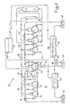
- a refrigeration installation 12 with points of use at different evaporation temperatures comprises, side by side, on the one hand, two refrigeration plants each operating in an autonomous manner, namely a refrigeration unit 13 with a single evaporation temperature -38 ° C having two normal operation compressor units 14, 15, a refrigeration unit 16 with a single evaporation temperature -10 ° C having three compressor units normal operation 17,18,19, and on the other hand a motor-compressor 20 usually operating to supply cold at its own points of use at an evaporation temperature of -1 ° C and accidentally serving as an emergency motor-compressor in the event of failure of one of the compressors of the two refrigeration units 13 and 16.
- the refrigeration unit 13 comprises a common suction manifold 21, and a common delivery line 22 for its compressor compressors 14 and 15.
- the common suction collector and the common delivery pipe for compressors of motor compressors 17, 18, 19 are indicated respectively at 23 and 24.
- the suction line 40 of the motor-compressor 20 which accidentally serves as an emergency motor-compressor; is connected on one side to the suction manifold 21 of the central unit 13 and on the other side to the suction manifold 23 of the central unit 16 respectively through valves 25 and 26 while the discharge pipe of this motor-compressor 20 is connected firstly to the common discharge line 22 of the central unit 13 and secondly to the common discharge line 24 of the central unit 16 respectively through valves 27 and 28.
- the suction line 40 of the motor-compressor 20 is further connected to the points of use 29 at an evaporation temperature of -1 ° C., through a valve 30.
- the refrigerant gas discharged by the motor compressors passes through an oil separator 31, condenses in a two-circuit condenser 32 common to the two central units and passes in the form of liquid in a tank 33 which supplies liquid refrigerant to the points of use 34 at evaporation temperature -38 ° C, and the expanded gas coming from these points of use 34 and entering the suction manifold 21 is sucked by these motor-compressors, the valves 25 and 27 separating the motor-compressor 20 from the central unit 13 then being closed.
- the refrigerant gas discharged by the motor compressors passes through an oil separator 35, condenses in the common condenser 32 and passes in the form of liquid in a reservoir 36 which supplies the points of use 37 with liquid refrigerant at evaporation temperature -10 ° C, and the expanded gas coming from these point of use 37, entering the suction manifold 23 is sucked in.
- these motor-compressors, the valves 26 and 28 separating the motor-compressor 20 from the central unit 16 then being closed.
- the liquid refrigerant tanks 33 and 36 of the power stations 13 and 16 are connected to the points of use 29 at evaporation temperature -1 ° C of the motor-compressor 20, through valves 38 and 39 respectively.
- the refrigerant gas discharged by the compressor 20 passes through the valve 28, the discharge pipe 24 and the oil separator 35 from the central unit 16, condenses in the condenser 32 and passes in the form of liquid in the tank 36 which supplies the points of use 29 with liquid refrigerant at evaporation temperature -1 ° C., and the expanded gas coming from this point of use 29, entering the suction line 40 through the valve 30, is sucked by this motor-compressor 20.
- the points of use 29 are not supplied with liquid refrigerant and the valves 30, 38 and 39 are closed.
- the valves 25, 27 are open and the valves 26, 28 are closed.
- the expanded gas coming from the points of use 34 is then also sucked up by the motor-compressor 20 through the valve 25 and the gas discharged by this motor-compressor 20 passes through the valve 27 in the common delivery line 22 of the power station 13 to go condensing in the condenser 32 and then accumulating in the tank 33 which supplies liquid refrigerant to the points of use 34 at evaporation temperature -38 ° C.
- valves 26, 28 are open and the valves 25, 27 are closed.
- the expanded gas coming from the points of use 37 is then also sucked in by the motor-compressor 20 through the valve 26, and the gas discharged by this motor-compressor 20 passes through the valve 28 in the common delivery line 24 to condense in the condenser 32 and then accumulate in the reservoir 36 which supplies liquid refrigerant to the points of use 37.
- the points of use 29 most often relate to air conditioning of the premises and a temporary halt in the production of cold at these points 29 during the troubleshooting of the damaged motocompressor does not cause any great inconvenience.
- the refrigeration installation 12 produced according to the invention does not require for its operating safety as a backup compressor, that only one compressor 20 which usually operates to supply cold at its own points of use 29 for an evaporation temperature between -10 ° C and + 5 ° C, is of this not only more economical but also has better capacity in the form of a number of points of use at different evaporation temperatures, three in this example, greater than the number of power stations constituting the installation, two in this example .
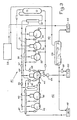
- a refrigeration installation 41 with points of use at different evaporation temperatures comprises on the one hand two refrigeration plants or stages, namely a stage low pressure 42 for an evaporation temperature of -38 ° C and a high pressure stage 43 for an evaporation temperature of -10 ° C mounted according to a compound technique with an introduction of refrigerant gas discharged from stage 42, in a suction manifold on stage 43, and on the other hand a motor-compressor 44 usually operating at an evaporation temperature of -1 ° C and accidentally serving as an emergency motor-compressor in the event of a failure of one of the motor-compressors these floors 42 and 43.
- the low-pressure stage 42 comprises two normal-functioning motor-compressors 45 and 46 which suck through a common suction manifold 47 of the refrigerant gas coming from its points of use 47 at evaporation temperature -38 ° C and discharge through a common discharge line 49 and an oil separator 50 in a common suction manifold 51 of the three normal-functioning motor-compressors 52, 53, 54 of the high-pressure stage 43.
- the suction line 61 of the motor-compressor 44 is connected through valves 62, 63, 64 respectively to the suction collectors 47, 51 of stages 42, 43 and to the points of use 60 of this motor-compressor.
- the discharge line 65 of the motor compressor 44 is connected, through valves 66 and 67, respectively to the common discharge lines 49 and 56 of stages 42 and 43.
- the refrigerant gas discharged by the compressor 44 passes through the valve 67, the discharge pipe 56 of the stage 43, the oil separator 57, condenses in the condenser 58 and passes in the form of liquid in the reservoir 59 which supplies liquid points of use 60 at evaporation temperature -1 ° C through the valve 68, and the expanded gas coming from these points of use 60 and entering the suction line 61 through the valve 64, is sucked by the motor-compressor 44.
- valves 62 and 66 are open and the valves 63 and 67 are closed.
- the expanded gas coming from the points of use 48 is then also discharged by the motor-compressor 44 through the valve 66 and the oil separator 50, and enters the common suction manifold 51 of stage 43 to then follow the normal path described in a previous paragraph.
- valves 62 and 66 are closed and the valves 63 and 67 are open.
- the expanded gas coming from the points of use 55 is then also sucked in by the motor-compressor 44 through the valve 63, and the gas discharged by this motor-compressor 44 passes through the valve 67 and enters the common delivery line 56 of the stage 43 to then follow the normal path described in a previous paragraph.
- the installation 41 produced according to the invention requires, for its operational safety, as back-up motor-compressors only one motor-compressor 44 for its two stages 42 and 43.
- this compressor 44 usually works to provide cold at its own points of use 60 at an evaporation temperature between -10 ° C and + 5 ° C.
- a refrigeration installation with several points of use at different evaporation temperatures further comprises two low pressure and high pressure stages and a motor compressor usually operating to provide cold at its own evaporation points and accidentally as an emergency motor compressor, similar to those of the second example of embodiment above, of other refrigeration stages for example a high pressure stage for an evaporation temperature -6 ° C.
- Such a refrigeration installation like that of the example above also comprising a single motor-compressor as emergency motor-compressor for the motor-compressors of all component stages, is advantageously very economical.
Landscapes
- Engineering & Computer Science (AREA)
- Physics & Mathematics (AREA)
- Mechanical Engineering (AREA)
- Thermal Sciences (AREA)
- General Engineering & Computer Science (AREA)
- Devices That Are Associated With Refrigeration Equipment (AREA)
- Separation By Low-Temperature Treatments (AREA)
- Cooling Or The Like Of Semiconductors Or Solid State Devices (AREA)
- Compressors, Vaccum Pumps And Other Relevant Systems (AREA)
Claims (3)
Priority Applications (1)
| Application Number | Priority Date | Filing Date | Title |
|---|---|---|---|
| AT82401820T ATE17780T1 (de) | 1981-10-06 | 1982-10-05 | Kuehlanlage mit unterschiedlichen verdampfungstemperaturen. |
Applications Claiming Priority (2)
| Application Number | Priority Date | Filing Date | Title |
|---|---|---|---|
| FR8118791 | 1981-10-06 | ||
| FR8118791A FR2514112A1 (fr) | 1981-10-06 | 1981-10-06 | Installation frigorifique a points d'utilisation a temperatures differentes d'evaporation |
Publications (2)
| Publication Number | Publication Date |
|---|---|
| EP0076763A1 EP0076763A1 (de) | 1983-04-13 |
| EP0076763B1 true EP0076763B1 (de) | 1986-01-29 |
Family
ID=9262792
Family Applications (1)
| Application Number | Title | Priority Date | Filing Date |
|---|---|---|---|
| EP82401820A Expired EP0076763B1 (de) | 1981-10-06 | 1982-10-05 | Kühlanlage mit unterschiedlichen Verdampfungstemperaturen |
Country Status (4)
| Country | Link |
|---|---|
| EP (1) | EP0076763B1 (de) |
| AT (1) | ATE17780T1 (de) |
| DE (1) | DE3268854D1 (de) |
| FR (1) | FR2514112A1 (de) |
Families Citing this family (3)
| Publication number | Priority date | Publication date | Assignee | Title |
|---|---|---|---|---|
| FR2630816B1 (fr) * | 1988-04-28 | 1991-01-11 | Electrolux Cr Sa | Centrale frigorifique alimentant des enceintes a au moins deux temperatures et procede de degivrage d'une telle centrale |
| CA2066371C (en) * | 1991-04-23 | 1998-09-15 | Masaru Kitaguchi | Refrigeration system consisting of a plurality of refrigerating cycles |
| CN100353128C (zh) * | 2001-06-26 | 2007-12-05 | 大金工业株式会社 | 冷冻装置 |
Citations (1)
| Publication number | Priority date | Publication date | Assignee | Title |
|---|---|---|---|---|
| FR458034A (fr) * | 1912-07-27 | 1913-10-01 | Societe De Moteurs A Gaz Et D Industrie Mecanique | Perfectionnements apportés à l'établissement des installations frigorifiques |
Family Cites Families (5)
| Publication number | Priority date | Publication date | Assignee | Title |
|---|---|---|---|---|
| FR826655A (fr) * | 1936-10-24 | 1938-04-06 | Sulzer Ag | Installation frigorifique comportant au moins deux compresseurs |
| CH241603A (de) * | 1944-07-01 | 1946-03-31 | Bbc Brown Boveri & Cie | Wärmepumpenanlage mit Turboverdichtern, die bei ihrem Lauf mit gleichbleibender Drehzahl angetrieben werden. |
| CH249816A (de) * | 1946-08-20 | 1947-07-31 | Bbc Brown Boveri & Cie | Wärmepumpenanlage mit Turboverdichtern, die bei ihrem Lauf mit gleichbleibender Drehzahl angetrieben werden. |
| FR2272349A1 (en) * | 1975-01-07 | 1975-12-19 | Emhart Corp | Refrigeration system with compressor - has compensating receiver accommodating gas in liquid state at constant pressure |
| US4184341A (en) * | 1978-04-03 | 1980-01-22 | Pet Incorporated | Suction pressure control system |
-
1981
- 1981-10-06 FR FR8118791A patent/FR2514112A1/fr active Granted
-
1982
- 1982-10-05 DE DE8282401820T patent/DE3268854D1/de not_active Expired
- 1982-10-05 EP EP82401820A patent/EP0076763B1/de not_active Expired
- 1982-10-05 AT AT82401820T patent/ATE17780T1/de active
Patent Citations (1)
| Publication number | Priority date | Publication date | Assignee | Title |
|---|---|---|---|---|
| FR458034A (fr) * | 1912-07-27 | 1913-10-01 | Societe De Moteurs A Gaz Et D Industrie Mecanique | Perfectionnements apportés à l'établissement des installations frigorifiques |
Also Published As
| Publication number | Publication date |
|---|---|
| EP0076763A1 (de) | 1983-04-13 |
| DE3268854D1 (en) | 1986-03-13 |
| FR2514112B1 (de) | 1983-12-02 |
| ATE17780T1 (de) | 1986-02-15 |
| FR2514112A1 (fr) | 1983-04-08 |
Similar Documents
| Publication | Publication Date | Title |
|---|---|---|
| US4361418A (en) | High vacuum processing system having improved recycle draw-down capability under high humidity ambient atmospheric conditions | |
| KR890006727Y1 (ko) | 공기 조화기(調和機)의 냉동 싸이클 | |
| US4476688A (en) | Refrigerant recovery and purification system | |
| US4151724A (en) | Pressurized refrigerant feed with recirculation for compound compression refrigeration systems | |
| CA2264997A1 (en) | High-speed evaporator defrost system | |
| EP0076763B1 (de) | Kühlanlage mit unterschiedlichen Verdampfungstemperaturen | |
| JPH05223366A (ja) | 遠心深冷システムにおけるオイル回収方法及び装置 | |
| JPH07301465A (ja) | 二段圧縮式冷凍装置 | |
| CA1129223A (en) | Refrigeration purging system | |
| EP0644390B1 (de) | Gaskompressionsverfahren und Vorrichtung | |
| US5269148A (en) | Refrigerant recovery unit | |
| EP0223669A1 (de) | Verfahren zur Konstanthaltung der Komposition eines gelagerten Produktes in einer Tieftemperaturflüssiggaslagerung | |
| US2724240A (en) | Refrigeration system | |
| FR2513747A1 (fr) | Installation frigorifique a multimotocompresseurs | |
| JP2004500509A (ja) | 凝縮水排出方法及び凝縮水排出装置 | |
| ES2212415T4 (es) | Instalacion (de refrigeracion) combinada y procedimiento para el accionamiento de una instalacion (de refrigeracion) combinada. | |
| US5214927A (en) | Method and apparatus for passive refrigerant and storage | |
| JP3319676B2 (ja) | 蓄熱式空気調和機およびその運転制御方法 | |
| EP0283340A1 (de) | Hilfskühlkreis für Kraftwagen | |
| CN211585889U (zh) | 一种大型油气回收装置 | |
| JPS61197793A (ja) | 多段複葉型真空ポンプにおける冷却方法 | |
| EP1938027A1 (de) | Vorrichtung und system für kältemittelkompressor mit saugleitungswärmetauscher | |
| JPH0429120Y2 (de) | ||
| JPH0792298B2 (ja) | 冷媒回収再生装置 | |
| JP3148403B2 (ja) | 空気調和装置 |
Legal Events
| Date | Code | Title | Description |
|---|---|---|---|
| PUAI | Public reference made under article 153(3) epc to a published international application that has entered the european phase |
Free format text: ORIGINAL CODE: 0009012 |
|
| AK | Designated contracting states |
Designated state(s): AT BE CH DE FR GB IT LI LU NL |
|
| 17P | Request for examination filed |
Effective date: 19830614 |
|
| RBV | Designated contracting states (corrected) |
Designated state(s): AT BE DE FR GB |
|
| GRAA | (expected) grant |
Free format text: ORIGINAL CODE: 0009210 |
|
| AK | Designated contracting states |
Designated state(s): AT BE DE FR GB |
|
| REF | Corresponds to: |
Ref document number: 17780 Country of ref document: AT Date of ref document: 19860215 Kind code of ref document: T |
|
| REF | Corresponds to: |
Ref document number: 3268854 Country of ref document: DE Date of ref document: 19860313 |
|
| PLBI | Opposition filed |
Free format text: ORIGINAL CODE: 0009260 |
|
| PGFP | Annual fee paid to national office [announced via postgrant information from national office to epo] |
Ref country code: AT Payment date: 19861031 Year of fee payment: 5 |
|
| 26 | Opposition filed |
Opponent name: LINDE AKTIENGESELLSCHAFT, WIESBADEN Effective date: 19861007 |
|
| PG25 | Lapsed in a contracting state [announced via postgrant information from national office to epo] |
Ref country code: GB Effective date: 19871005 |
|
| BERE | Be: lapsed |
Owner name: FROID SATAM BRANDT Effective date: 19871031 |
|
| RDAG | Patent revoked |
Free format text: ORIGINAL CODE: 0009271 |
|
| STAA | Information on the status of an ep patent application or granted ep patent |
Free format text: STATUS: PATENT REVOKED |
|
| GBPC | Gb: european patent ceased through non-payment of renewal fee | ||
| 27W | Patent revoked |
Effective date: 19880304 |
|
| GBPR | Gb: patent revoked under art. 102 of the ep convention designating the uk as contracting state | ||
| REG | Reference to a national code |
Ref country code: GB Ref legal event code: 7102 |
|
| REG | Reference to a national code |
Ref country code: FR Ref legal event code: ST |